Université de Montréal
Lumbar-Sacral Pedicle Screw Insertion with Preoperative CT-based Navigation
Par
Benoît Goulet, MD, FRCSC, FACS
Programme de Sciences Biomédicales
Faculté de Médecine
Mémoire présenté à la Faculté des Études Supérieures
En vue de l’obtention du grade de maîtrise (M.Sc.)
En Sciences Biomédicales
Mai, 2009
©, Benoît Goulet, 2009
Université de Montréal
Faculté des Études Supérieures
Ce mémoire intitulé:
Lumbo-sacral pedicle screw insertion with preoperative CT-based navigation
Présenté par:
Benoît Goulet, MD, FRCSC, FACS
A été évalué par un jury composé des personnes suivantes:
_______Stéfan Parent______
Président-rapporteur
____Jacques A. DeGuise____
Directeur de recherche
______ Louis D. Collins_____
Co-directeur
______Frédéric Lavoie______
Membre du jury
Résumé
Objectif: Nous avons effectué une étude chez 135 patients ayant subis une chirurgie lombo-sacrée avec vissage pédiculaire sous navigation par tomographie axiale. Nous avons évalué la précision des vis pédiculaires et les résultats cliniques.
Méthodes: Cette étude comporte 44 hommes et 91 femmes (âge moyen=61, intervalle 24-90 ans). Les diamètres, longueurs et trajectoires des 836 vis ont été planifiés en préopératoire avec un système de navigation (SNN, Surgical Navigation Network, Mississauga). Les patients ont subi une fusion lombaire (55), lombo-sacrée (73) et thoraco-lombo-sacrée (7). La perforation pédiculaire, la longueur des vis et les spondylolisthesis sont évalués par tomographies axiales postopératoires. Le niveau de douleur est mesuré par autoévaluations, échelles visuelles analogues et questionnaires (Oswestry et SF-36). La fusion osseuse a été évaluée par l’examen des radiographies postopératoires.
Résultats: Une perforation des pédicules est présente pour 49/836 (5.9%) des vis (2.4% latéral, 1.7% inférieur, 1.1% supérieur, 0.7% médial). Les erreurs ont été mineures (0.1-2mm, 46/49) ou intermédiaires (2.1 - 4mm, 3/49 en latéral). Il y a aucune erreur majeure (≥ 4.1mm). Certaines vis ont été jugées trop longues (66/836, 8%). Le temps moyen pour insérer une vis en navigation a été de 19.1 minutes de l΄application au retrait du cadre de référence. Un an postopératoire on note une amélioration de la douleur des jambes et lombaire de 72% et 48% en moyenne respectivement. L’amélioration reste stable après 2 ans. La dégénérescence radiologique au dessus et sous la fusion a été retrouvée chez 44 patients (33%) and 3 patients respectivement (2%). Elle est survenue en moyenne 22.2 ± 2.6 mois après la chirurgie. Les fusions se terminant à L2 ont été associées à plus de dégénération (14/25, 56%).
Conclusion: La navigation spinale basée sur des images tomographiques préopératoires est une technique sécuritaire et précise. Elle donne de bons résultats à court terme justifiant l’investissement de temps chirurgical. La dégénérescence segmentaire peut avoir un impact négatif sur les résultats radiologique et cliniques.
MOTS CLÉS • navigation par tomographie axiale • spondylolisthésis • vis transpédiculaires • fusion lombaire•
Abstract
Objective: The authors studied 135 consecutive patients following a lumbo-sacral fixation using pedicle screws and CT-based navigation to evaluate pedicle screw accuracy and clinical outcomes.
Methods: The series included 44 men and 91 women (mean age 61 years, range 24-90 years). All 836 screws were planned with pre-operative CT-Scans in a navigation system (SNN, Surgical Navigation Network, Mississauga, Ontario, Canada) for diameter, length and direction. Fixation included the lumbar spines only (55), the lumbo-sacral spine (73) or the thoraco-lumbo-sacral spine (7). Pedicle perforation, screw length and spondylolisthesis were assessed on post-operative CT-Scan. Pain was surveyed using self-rated scales, visual analogue scales, Oswestry and SF-36 questionnaires. Bony union was assessed on post-operative follow-up radiographs.
Results: Pedicle perforation was found in 49/836 (5.9%) screws (2.4% laterally, 1.7% inferiorly, 1.1% superiorly, 0.7% medially). The errors were minor (0.1-2mm, 46/49) or intermediate (2.1 – 4 mm, 3/49). All intermediate errors were lateral. There were no major errors (≥ 4.1mm). Some screws were judged too long (66/836, 8%). The average time to insert one screw with navigation was 19.1 minutes from application to removal of the reference frame. The amount of improvement at one year post-operation for self-rated leg and back pain were 72% and 48% respectively. The improvement was stable over 2 years. Above-level and below-level radiological degenerations were found in 44 patients (33%) and 3 patients respectively (2%) and occurred on average 22.2 ± 2.6 months after the surgery. Fusions ending at L2 had the most degenerations (14/25, 56%).
Conclusion: CT-based preoperative navigation for lumbo-sacral pedicle screw insertion is accurate and associated with a good short term outcome, making it worth the investment of the additional time required. Segmental degeneration may have a negative effect on radiological and clinical outcomes.
KEY WORDS • CT-based spinal navigation • spondylolisthesis • transpedicular screws • lumbar fusion • segmental
Table of Contents
Résumé ...i
Abstract... iii
Table of Contents... v
List of Tables ... vii
List of Figures ...ix
Abbreviations ...xi Dedication... xii Acknowledgements ... xiii Disclaimer... xiv CHAPTER 1 - Introduction ... 1 A) Motivation ... 1
B) Overview and organization of the thesis. ... 3
C) Scientific contributions ... 4
CHAPTER 2 – Spine anatomy, pathology, surgical technique and navigation techniques ... 5
A) Spine anatomy ... 5
B) Degenerative spine disease ... 8
C) Surgical management of degenerative spine disease ... 9
D) Anatomical constraints of pedicle screw insertion ... 10
E) Description of the standard surgical technique ... 11
F) Navigation concepts and surgical techniques ... 18
G) Validation and verification of the errors ... 24
H) Assessment of bony union ... 25
CHAPTER 3 – Literature Review ... 27
B) Radiological Evaluation of Error ... 28
C) Anatomical Landmarks and/or Intraoperative Fluoroscopy ... 30
D) CT-based Navigation ... 34 E) Anterior error ... 38 F) 2D-fluoroscopy Navigation ... 39 G) 3D-fluoroscopy Navigation ... 41 H) Intraoperative CT-Scan ... 42 I) Ultrasound ... 43 J) Surgical Outcomes ... 44
Clinical Outcomes and Measures ... 44
Fusion and Graft ... 46
Adjacent Level Degeneration... 47
Time for screw insertion ... 49
Infection rate ... 50
CHAPTER 4 - Manuscript Presentation, Clinical Material, Methods and Results ... 51
FIGURES AND TABLES of article ... 71
CHAPTER 5 – Discussion and Conclusion of the Thesis ... 85
A) Historical perspectives ... 85
B) Discussion of our results ... 85
C) Other navigation techniques ... 92
D) New research ideas ... 93
E) Conclusions ... 94
REFERENCES ... 95
ANNEX 1 – Poster Presentation ... 106
ANNEX 2 - CT-Scan Protocol Recommended by SNN ... 107
List of Tables
Table 3. 1 Methods of measurement of errors ... 30
Table 3. 2 Literature review for lumbo-sacral pedicle error with landmarks, radiography and fluoroscopy insertion techniques ... 32
Table 3. 3 Pedicle screw errors in the thoracic spine with anatomical or spinal navigation ... 33
Table 3. 4 Literature review for lumbar pedicle error with pre-operative CT-Scan technique ... 37
Table 3. 5 Anterior vertebral error for all techniques ... 39
Table 3. 6 Results of 2D-Fluoroscopy for insertion of lumbar screws ... 41
Table 3. 7 3D-rotational radiographs for thoracic pedicle screws ... 42
Table 3. 8 Adjacent level disease... 48
Table 3. 9 Time for screw insertion ... 49
Table 3. 10 Infection rate ... 50
Table 4. 1 - Symptoms before surgery ... 71
Table 4. 2 - Indications for surgery... 72
Table 4. 3 - Previous surgery ... 72
Table 4. 4 – Medial and lateral screw errors at pedicle level and length errors. ... 77
Table 4. 5 - Superior and Inferior errors at pedicle level ... 79
Table 4. 7 - Major procedure-related complications ... 81
Table 4. 8 - Above level degeneration per level ... 82
Table 4. 9 - Comparison of levels with and without degenerations ... 82
List of Figures
Figure 2. 1 Spine curvatures ... 6
Figure 2. 2 Lumbar vertebral anatomy ... 6
Figure 2. 3 Anterior and posterior nerve anatomy ... 7
Figure 2. 4 Lateral spine nerve anatomy ... 7
Figure 2. 5 Surgical positioning and incision planning ... 12
Figure 2. 6 Iliac crest preparations... 12
Figure 2.7 Spine exposure ... 13
Figure 2. 8 Pedicle entry point ... 14
Figure 2. 9 Pedicle tracts orientation ... 15
Figure 2. 10 Pedicular screws ... 16
Figure 2. 11 Screws inserted ... 17
Figure 2. 12 Rod insertion ... 17
Figure 2. 13 Final screws and rods construct ... 18
Figure 2. 14 Navigation planning ... 19
Figure 2. 15 Navigation instruments... 20
Figure 2. 17 Accuracy check ... 22
Figure 2. 18 Intraoperative navigation images ... 24
Figure 2. 19 Screw error assessment ... 25
Figure 2. 20 Bony union grading ... 26
Figure 4.1 – Intraoperative images of navigation screen ... 71
Figure 4. 2 – Pedicle and length error measurement on axial CT-Scan ... 73
Figure 4. 3 – S1 length errors ... 73
Figure 4. 4 - T10-S1 sagittal pedicle error ... 74
Figure 4. 5 – Back pain measurements ... 74
Figure 4. 6 - Leg pain measurements ... 75
Figure 4. 7 - Satisfaction degree ... 75
Figure 4. 8 – Self-rated percentage of overall improvement & Oswestry Disability Index ... 76
Figure 4. 9 - Short Form SF-36 scores at 1 year follow-up ... 76
Figure 4. 10 - Short Form SF-36 over time ... 77
Figure 4. 11 - Screw diameter per vertebra... 80
Figure 4. 12 - Navigation time per number of vertebrae fused. ... 84
Abbreviations
ASD: Adjacent segment disease ALD: Above level degenerationALIF: Anterior lumbar interbody fusion
ABLD: Bellow level degeneration
DDD: Degenerative disc disease
Inf: Inferior
Lat: Lateral
Med: Medial
MRI: Magnetic resonance imaging
NSt: Not stated
NS: Not statistically significant
PLIF: Posterior lumbar interbody fusion
PSF: Pedicle screw fixation
SNN: Surgical Navigation Network
Sup: Superior
TLIF: Transverse lumbar interbody fusion
VAS: Visual analogue scale
Dedication
This thesis is dedicated to those who made it possible:
Julie, my wife; Elizabeth, Stephanie and Frederick, my children; Jean-François, Louis, Lahbib, and Jacques.
“Although a thorough knowledge of surgical anatomy and technique remains the most essential aspect of a
spinal surgeon’s navigational experience, the information acquired from image guidance can assist even the most experienced surgeon.” Holly 47
Acknowledgements
I would like to acknowledge: All of my academic supervisors; Professor Louis Collins who supervised my work. Professor Jacques DeGuise who helped to support my candidature at the University of Montreal.
All personnel of the navigation unit; Lahbib Soualmi, PhD, was in charge of all computer aspects of the navigation system for procedures. He participated in almost all procedures and was very supportive to help us persevere with the difficulties of registration in CT-based navigation. Manni Podaras and Julie Dumouchel, in Lahbib Soualmi’s team, helped to create the segmentation of the spine images and participated in some technical aspects of the procedures.
All students, residents and fellows: Jean-François Couture, a medical student who helped cumulates and analyze the data. He is a co-author of the article. Julie Pelletier, MSc. helped with data acquisition of the first 25 patients and helped review this manuscript. Zachary Schwartz, a student in physiology, helped with the Short-Form 36 analysis. Anthony Bozzo helped review the thesis manuscript. The neurophotography department helped with some illustrations.
Finally, the FRSQ, Le Fond de Recherche en Santé du Québec and Stryker Canada for their academic financial support.
Disclaimer
Dr Benoît Goulet, MD, FRCSC, FACS, received a 2-year grant from the FRSQ for his Masters in Biomedical Science at the University of Montreal. This work has been also supported by Stryker Canada with a salary research award.
CHAPTER 1 - Introduction
A) Motivation
Spine surgeons are confronted to treat many patients with instability to their spine. Causes of spine instability can be: degenerative, infectious, tumoral, traumatic and iatrogenic. These conditions are often associated with narrowing of the spinal canal and foramen causing pain and neurological deficits. The surgery for these conditions has 3 goals: decompression, stabilization and realignment of the spine 87. Decompression is done by a laminectomy or a discectomy. Stabilization is done by fixation, which in the lumbar spine, typically consists of pedicle screws that are fixed with rods and bolts. A bone graft is inserted in addition to the screws to create a bony fusion as screws alone will become loose over time. Realignment of the spine is done with maneuvers on the rods and insertion of spacers into the disc spaces.
Pedicle screw insertion is challenging as the pedicle itself consists of only a narrow passage of bone into which the screws need to be inserted. This funnel of bone has hard cortical bone outside and softer cancellous bone inside through which the screw is passed. Beyond the pedicle, the screw anchors in the vertebral body. If a screw is misplaced, it may injure the spinal nerves around the pedicle or the vessels or soft tissues in front of the vertebral body 85.
One of the difficulties with this type surgery is that the pedicle is hidden under the lamina and the facet joints. The sides and the front of the vertebral body including the pedicle are not usually exposed in lumbar fusion surgeries. The surgeons have to rely on the anatomy of the bone exposed to evaluate the best screw path. Classic screw entry
points have been described to guide the entry point of the screw. Often, in the lumbar spine, the pedicles are bigger in size and allow many options in screw directions.
Despite this more favorable anatomy compared to the thoracic and cervical spine, many pedicle screws inserted with traditionally anatomical landmarks have failed to be properly placed. Using such anatomical landmarks, surgeons have reported high rates of pedicle perforations. Fortunately the problem of accuracy of pedicle screws has led to only a few neurological injuries. For the rare patient that has pain or neurological deficit, an improperly inserted screw is an important problem.
In the search for accuracy, surgeons have used many techniques: Pedicle sounding (palpation), laminotomy, laminectomy, intraosseous endoscopy, saline challenge, pedicle impedance testing (electromyography), intra-operative fluoroscopy, 2D-fluoroscopy, preintra-operative CT-based navigation and intraintra-operative CT-Scan. Each of these techniques has associated inaccuracies, risks, cost and limitations. Simple techniques such as fluoroscopy and non-imaging techniques did not have high accuracy levels of screw insertion.
More advanced imaging techniques as 2D-fluoroscopy rely only on a lateral and antero-posterior radiological view taken during surgeries. It does not allow a 3-dimension pre-operative planning and has a significant error rate reported in the literature. Intra-operative CT-Scan has good accuracies, but until recently with the development of the O-Arm (Medtronics), this technique was not easily available in operating rooms.
The ideal system to do image-guided surgery should have many qualities. It should image the patient with minimal or no radiation. It should adequately image the bony structures required for screw insertion and allow visualization of any stenotic areas. It should allow the planning of surgeries and could allow analysis of biomechanical scenarios. It should do an automatic registration of the bone anatomy. All instruments should be tracked and the insertion of
the screw should be automated. The system should allow on site confirmatory imaging so that rare errors would be corrected during surgery. The system should be inexpensive, small and easy to use by surgeons.
When we started to look for a navigation system in our hospital in 2001, the closest solution to improve the accuracy of pedicle screw insertion was to use a pre-operative CT-Scan navigation system. It has the advantages of adequately imaging the bone, of pre-operative planning and showing 3D anatomy. It is available in most centers that perform cranial image-guided surgery. It has the disadvantage of requiring a lengthy and sometimes frustrating registration process and increases operating time. Also it does not allow reimaging of the patient during surgery and relies on navigation specialists to manage the system.
The literature has repetitively shown the superiority of CT-based navigation over anatomical landmark-based techniques, fluoroscopy or laminotomies for lumbar pedicle screw insertion. Intraoperative radiographs or fluoroscopy can help the surgeon to localize the pedicle but its usefulness has been questioned 123. It is difficult for the reader to analyze the literature on pedicle accuracy as the authors used different methods to quantify screw errors and some failed to include small errors in their errors rates. Considering the difficulties with CT-based navigation and the low rate of complications of small and moderate pedicle errors, most surgeons use anatomical landmarks for screw insertion.
B) Overview and organization of the thesis.
The thesis is based on a manuscript that will be submitted for publication. The other chapters of the thesis are developed to support the reader in the understanding of the article. The thesis will be organized in the following order: Chapter 1, Introduction; Chapter 2, Review of basic anatomy and ancillary surgical techniques; Chapter 3, Review of the literature on spinal image-guided surgery and on clinical measurements; Chapter 4, presentation of the manuscript; and Chapter 5, Discussions and conclusions. The primary goal of the study was to evaluate the
accuracy of pedicle screw insertion. We quantified pedicle screw error in all four quadrants of the pedicle (medial, lateral, inferior and superior). We also measured the length of the screws respective to the anterior vertebral body wall. The pedicle error rate was about 6% per screw. All pedicle errors were judged inconsequential. Of all the
screws, 8% were judged to be too long and screws were much too long (≥ 6mm) 3% of the time. None of the too
long screws caused vascular injury. As secondary goals we evaluated clinical variables. Pain and clinical outcomes were assessed by self-reported scales, visual analogue scales, Oswestry disability index questionnaires and Short-Form 36 questionnaires. Radiological exams were reviewed to assess early and late radiological results. Lumbar fusions patients report good satisfaction rate, however, the vertebral level above the fusion has failed in the long term in some cases.
C) Scientific contributions
We presented the largest series on lumbar pedicle screws inserted with the pre-operative CT-based
navigation.
We confirmed the good clinical early results found in the literature for lumbar fusions.
We confirmed that above level degeneration is a significant cause of long-term morbidity after a lumbar
fusion.
CHAPTER 2 – Spine anatomy, pathology, surgical technique and
navigation techniques
Thorough knowledge of the specific anatomy of the patient to be operated is very important for the surgeon. This knowledge is acquired though reading of textbooks, practicing on spine models, through the training process, by analyzing the preoperative imaging and during surgery itself. Like an airplane pilot, the surgeon makes a plan of the procedure. The surgeon organizes the surgery into different stages. Each stage follows a routine, so the surgery can be performed safely and in an expedited way. The classic pedicle screw entry points are well mastered by experience surgeons but are sometimes difficult to see in much degenerated cases. Such specific circumstances are better to be known in advance. The navigation system allows a proper planning for the patient’s specific anatomy. This section will cover A) Spine anatomy, B) Degenerative spine diseases, C) Surgical management of degenerative spine disease, D) Anatomical constraints of pedicle screw insertion, E) Description of the standard surgical technique, F) Navigation concepts and surgical techniques, G) Validation and verification of the errors and H) Assessment of bony union.
A) Spine anatomy
The spine has 7 cervical vertebrae, 12 thoracic vertebrae, 5 lumbar vertebrae, a sacrum composed of 5 fused segments and the coccyx composed of 4 fused segments (Figure 2.1). The spinal curves (cervical lordosis, thoracic kyphosis and lumbar lordosis) distribute the axial load and allows the spine to be 30 times more elastic than if was straight 29. Each vertebra has a specific shape with variations between levels and between different patients. The typical lumbar vertebra has an anterior vertebral body that connects through two pedicles and a posterior arch (figure 2.2). Inside there is a spinal canal and a foramen on each side through which pass the spinal cord and spinal nerves roots respectively (figures 3 and 4).
Figure 2. 1 Spine curvatures
a. Anterior view of a plastic spine model b. Posterior view c. Left lateral view d. Right lateral view
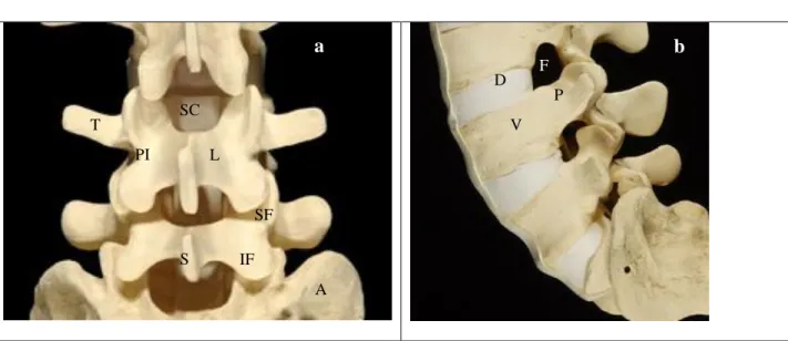
Figure 2. 2 Lumbar vertebral anatomy
a,b. Close up of a sawbone spine model. Posterior view of L3, L4, L5 vertebrae and upper sacrum with transverse process (T),
spinous process (S), lamina (L), superior facet (SF), inferior facet (IF), pars interarticularis (PI), spinal canal (SC), pedicle (P), foramen (F), vertebral body (V), disc (D) and ala of sacrum (A). The pedicle is in the superior 1/2 of the vertebra. A pedicle screw is usually closer to the facet above than below.
T S A SF IF L P V D PI F SC
a
b
c
d
a
b
Figure 2. 3 Anterior and posterior nerve anatomy
a. Anterior view of the lumbar spine showing the nerves grouping to create the lumbar-sacral plexus. b. Posterior view of the
lumbar spine with the posterior part of the sacrum removed to show the dural sac and sacral nerves. c. Posterior view of the spine showing on top the yellow ligament (Y) and at the bottom the dural sac between the laminae. On the side the nerves come out the foramen in front and above the transverse processes.
Figure 2. 4 Lateral spine nerve anatomy
a. The spine is showed without the iliac bone. The sciatic nerve comes out the sciatic notch. b. The pelvic bone hides the side of
the spine. c. In the foramen the nerves enlarge at the location of the dorsal root ganglion. d. Axial view of L3 vertebral body. Approximate angle of pedicle respective to the sagittal axis (red lines).
The anatomy of the pedicle and it’s variations were well described by Saillant in 1976 108 and Zindrick in 1987 134. In the lumbar spine, the transverse (horizontal) diameter of the pedicle increases from L1 (approximately 8mm 108 ,134) to L5 (16 -18 mm 108,134). The pedicle vertical diameter (height) is more constant throughout the lumbar spine
A
Y
a
b
c
measuring approximately 15 mm. The angle between the sagittal axis and the pedicle in more pronounced in L5 at about 30and decreases progressively from L5 to L1 at about 0- 10 depending on the study (Figure 2.4) 108,134. The length of bone accessible for screw fixation (vertebral body and pedicle length) is quite constant in the lumbar spine (43 - 50 mm 108 ,134).
B) Degenerative spine disease
Instability of the spine can be caused by trauma, tumors, infections, degeneration or after decompressive surgery. The most frequent cause of instability in an elective practice is degeneration of the spine. Causes of spine degeneration include chronic overload, chronic multi-traumatism and sequelae of acute trauma 29. In the lumbosacral spine, L4-L5 and L5-S1 are the most frequent levels involved because this area has the highest dynamic and static loads.
Degeneration of the vertebrae creates “spondylolis deformans” shown on radiographs as osteophytosis or bone spurs. They are found in 60% of women and 80% of men after age 50. The facet joints are frequently involved in osteoarthritis. Facet joint osteoarthritis is seen in imaging as joint space narrowing, subchondral sclerosis and cysts, osteophytosis, ligament thickening, intra-articular vacuum (gas in the facet joints) and joint fluid. Severe facet osteoarthritis can cause lateral recess, neural foramen stenosis, central canal stenosis and or instability. Facet instability can cause an anterior degenerative spondylolisthesis with one vertebra slipped against the other. Degenerative spondylolisthesis is found in about 4% of the elderly population. So degeneration of the spine is a continuous process.
Spondylolisthesis is most often found at L4-L5 and L3-L4 levels because of the more sagittal orientation of the joints. L5-S1 is protected by the lumbo-sacral ligaments. Anterior spondylolisthesis is classified in 4 grades according to Meyerding: grade 1 (slippage 1% to 25%; most frequent), grade 2 (26% to 50%), grade 3 (51%-75%)
and grade 4 (76% -100%).86 Spondyloptosis, sometimes called grade 5, describes a vertebra in front of the other. Posterior spondylolisthesis, found less frequently, is associated with loss if disc height and facet sliding and is usually mild. We find spondylolisthesis in about 3% to 7% of the population.
Stenosis is a narrowing that can be localized centrally (middle of canal), in the lateral recess (sides of the canal) or in the foramen (exits for nerve roots). A stenosis can be caused by degenerated discs, facet joints, osteophytes at the edges of a vertebral body, spondylolisthesis, spondylosis, and hypertrophy of the ligamentum flavum 29,38.
Fissures in the radial direction can rupture the annulus fibrosus (outside hard part) and extend in the nucleus pulposus (inside soft part) causing a disc herniation. Disc herniation is a localized displacement of the nucleus pulposus outside the limits of the normal disc. A bulging disc is broader and follows the contours of the annulus fibrosus usually less than 3 mm beyond the edges of the vertebral body.
C) Surgical management of degenerative spine disease
In patients with sciatic leg pain, the first goal of spine surgery is decompression 87. For central canal stenosis without instability, a simple laminectomy is the most frequently used operation. Patients with spondylolisthesis are most frequently managed by a decompression and stabilization. Pedicle screws and rods have become the main way to fix the spine. When performing pedicle screw fixation variability in pedicle width, height and orientation 134 should be considered.
To increase the strength of a posterior fusion and help with the reduction, the disc space can be fused as well. This intersomatic fusion can be achieved through an anterior approach (ALIF, anterior lumbar interbody fusion), a postero-lateral approach (TLIF, transverse lumbar interbody fusion), posterior approaches (PLIF, posterior lumbar interbody fusion) or a lateral approach (XLIF, Extreme lateral interbody fusion).
Instrumentation alone without bone graft or bone substitute may fail over time. Best results of union are obtained with the patient’s own bone. Because of morbidity of iliac crest harvesting and insufficient amount of bone collected from laminectomy, other substitute such as allograft, demineralized bone matrix and bone promoting proteins are used with certain success.
D) Anatomical constraints of pedicle screw insertion
The pedicle is like a tube 103. Depending on the size of the pedicle and the screw size, different trajectories can be used to insert the screw without breaching the sides of the pedicle. Rampersaud described possible variation in screw direction for translation (sideway variation) and rotation from C2 to L5 103. Of all the vertebrae, the maximal variability was at L5 where 3.8 mm of sideway translation and 12.7º of rotation was anatomically possible 103. L1 has only 0.65 mm of possible translation and 2.1 of rotation allowed 103. This specific anatomy would make L5 the easiest vertebra to instrument. In reality L5 is a difficult vertebra to instrument due to its deeper location in the lordosis of the lumbar spine.
In the lumbar spine there is 2mm of epidural space between the nerves and the pedicle allowing a safety margin while inserting pedicle screws 32. In the thoracic spine, there was no space found between the pedicle and the dura 20. The average distance of the pedicle to the superior root ranged from 1.9 to 3.9mm and the distance from the
pedicle to the inferior root ranged from 1.7 to 2.8mm. In the thoracic spine, the spinal cord is more at risk than nerve roots that give intercostals nerves.
S1 pedicle screws pose different problems. Typically the screw is inserted bi-cortically, across the anterior vertebral cortex, for a good fixation. The S1 pedicle is softer and the fusion to S1 has a higher rate of non-union. The entry point is usually at the inferior and lateral corner of L5-S1 facet joint. This point is also defined with navigation. The screw is directed medially. The screw usually ends in the medial zone of the sacrum called the safe zone, just
below the S1 promontory 87. It allows for screw placement away from the sacro-iliac joint and the neurovascular structures located more laterally.
S1 screws pose a second problem. The iliac crest can block the trajectory for a midline S1 screw insertion in 76% of males and 85% of females 54. In reality, such a classic midline trajectory is not often feasible due to the insufficient possible muscle retraction necessary. Alternatively, the screw can aim be inserted laterally, through the smaller lateral safe zone of Mirkovic 87.
The success of pedicle screw insertion depends on identification of landmarks, surgeon experience, spine level of fixation and screw size. To understand the pedicle anatomy surgeons study before the surgery the pedicle anatomy on plain X-rays, CT-Scans or MRI’s. More information during the surgery can be taken from the palpation of the pedicle after a laminectomy or laminotomy.
E) Description of the standard surgical technique
For lumbo-sacral fusions, patients are positioned prone with the hips in slight extension to keep an adequate lumbar lordosis (Figure 2.5). The incision is midline (Figure 2.6). The autologous bone graft is resected in the pelvic bone at the postero-infero iliac crest area trough the same incision by following the thoraco-lumbar fascia (Figure 2.6). The spinous processes, the laminae, the facet joints and the transverse processes are exposed and the muscles are retracted to allow screw insertion (Figure 2.7).
Figure 2. 5 Surgical positioning and incision planning
a. Positioning for lumbo-sacral fusions in the operating room. b. Incision drawing with buttock on right side. Inferiorly, there is
marking of postero-superior iliac crest site harvesting.
Figure 2. 6 Iliac crest preparations
a. Midline incision and left iliac crest site harvesting marked with felt pen. b. Resection of lateral margin of left iliac crest with an
osteotome.
After iliac crest closure, the spine is exposed with dissection of the muscles at the levels to be decompressed and fused. The capsule of facets not to be fused is preserved. The interspinous ligaments of levels not fused are also preserved to prevent adjacent level degeneration (Figure 2.7).
a
b
b
a
Figure 2.7 Spine exposure
Exposed lumbar spine with retractors holding muscles. In midline there are the spinous process and laterally the facet joints.
In the lumbar spine, the classic entry point for pedicle screws insertion is found at the junction of the mid-part of the transverse process and the mamillary process found at the base of the superior articular process (Figure 2.8).
Two main classic entry points have been described in the literature. The Roy-Camille entry point is 1 mm below the facet joint and the screw is directed straight (0) in the pedicle and the vertebra 107. The Weinstein entry point is more lateral at the base of the superior facet in the mamillary process and the direction in angled more medially (Figure 2.8) 123. A too medial approach can injure the facet and a too lateral approach can break the pedicle laterally 71. The Weinstein entry point is the most frequently used by spine surgeons. In a cadaveric experiment Weinstein
showed that their technique had 7% of pedicle perforation compared to 21% with the Roy-Camille technique. The Weinstein technique was more accurate in the L3-S1 area and the Roy-Camille technique was better in the T12-L2 area 123 where the pedicle angle is closer to 0º as described earlier.
Figure 2. 8 Pedicle entry point
a. Sawbone phantom right lateral view with black markings of the transverse process and the inferior portion of the superior
articular process (mamillary process). b. Close up of the entry point (red arrow) for a classic pedicle screw entry in line with the transverse process section and the mamillary process nibbled away. In real surgery just the entry point is filed away preventing injury to the facet joint. c. Pilot hole for the screw created by the pedicle finder (not showed) and palpation of the pedicle with a ball tip.
The pedicle is entered with a flat probe (pedicle finder) in the direction of the screw planning. That non-sharp instrument can redirect itself somewhat within the confines of the pedicle cortex. In cases of very sclerotic pedicles (ossified pedicles) a drill bit is used to complete the trajectory. George 31 demonstrated that preparing that pedicle with a probe or a drill had no significant difference in screw pull-out. After the pilot hole is done, a ball tip instrument is used to feel that the wall of the pedicle is intact in all 4 quadrants: medial, inferior, lateral and superior (Figure 2.8). The anterior margin of the vertebra is felt to evaluate the maximal length of screw possible (Figure 2.8).
Typically in the thoracic and lumbar spine, the anterior cortex is not crossed by the screw to avoid injury of the aorta or inferior vena cava. The only exception is at the S1 level, where due to lower risk of vessel injury, the anterior cortex is engaged to increase screw pull-out strength. Also, S1 has a pedicle that is mostly cancellous and in which the pull-out strength can be weak. S1 is often the end of the construct where a lot of stress is applied. Before inserting the screw, preparation on the screw threads is done with a tap. Undertapping 1mm less than the screw size increases peak insertional torque and increases the fixation strength in the thoracic spine 64. The insertion torque is correlated with the stability of the hardware 132. The pedicle is responsible for 60% of the pullout strength and for 80% of the cephalocaudal stiffness. Misenhimer 89 wrote that the screws have their strength from cancellous
purchase and not from cutting into the cortex of the pedicle. The inner pedicle diameter can be evaluated by CT-Scanning and is a few mm smaller than the outside cortex 89. A too big screw will cause pedicle expansion (plasticity) before fracture of the pedicle. Fractures of pedicles occur more often laterally (72%) than medially (28%). Screw pull-out and insertional torque is increased with screws aimed at the superior endplate instead of going to the inferior endplate in the thoracic spine 75 . As shown in figure 2.9, the orientations of the screws are directed medially and converge posteriorly to follow the pedicle trajectories. The posterior convergence is due to the lordosis in the lumbar spine.
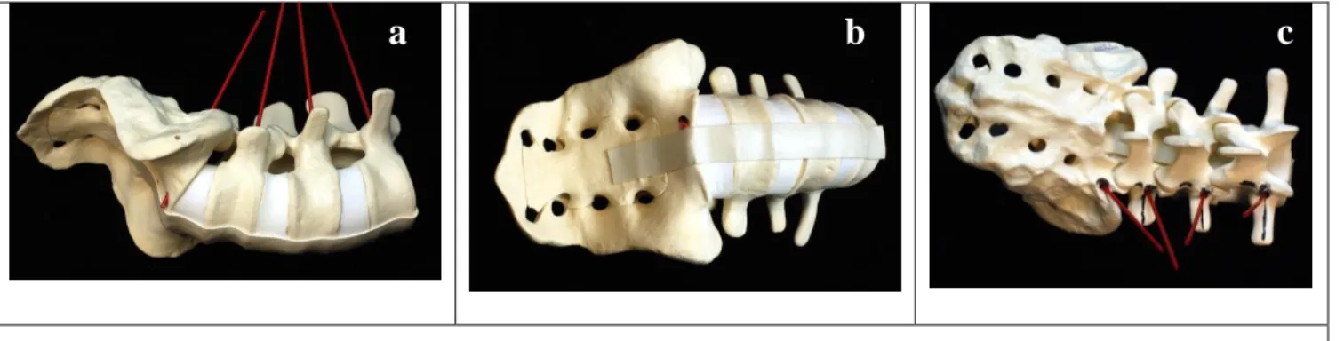
Figure 2. 9 Pedicle tracts orientation
a. Right side view of L3 to sacrum with red plastic tubes showing perforation of the anterior cortex in sacrum but not at other levels. b.
Red plastic tube coming out at S1 on the right side. c. The red posts show the trajectories converge posteriorly.
Pedicle screw systems are available in different sizes, thread shapes, and different alloys. The screws heads are either polyaxial or monoaxial. Most surgeons now use cases polyaxial titanium screws for lumbar degenerative cases. The CD - Horizon M8 system (Medtronic Sofamor Danek, Memphis, TN) is available in 4.5, 5.0, 5.5, 6.5 and 7.5 mm diameters in a wide selection of lengths (Figure 2.10). XIA-II system (Xia-II; Stryker Spine, Allendale, NJ), is available in 4.0, 4.5, 5.0, 5.5, 6.5, 7.5 and 8.5 mm diameters, and in multiple lengths (Figure 2.10). The availability of multiple screw sizes allows for a better fit of the screw within the pedicle internal wall. Too big a screw may fracture a pedicle wall, thus weakening the construct. In big pedicles, a 6.5mm screw is usually mechanically strong enough and has a good purchase, except in osteoporosis. Too small screws might break or become loose, especially in osteoporotic bone. In osteoporotic bone, most surgeons will reinforce screw purchase
with the addition of bone cement in the screw path. In S1, bigger screws of about 7.5mm in diameter are used for better bicortical purchase.
The ideal screw diameter is about 80% of the pedicle diameter 121. If the pedicle cortical margin is violated the pullout strength was diminished by 11% in one study 31. Zindrick 135 found that larger diameter, full-threaded screws and screws that cross the anterior cortex were the strongest to pull-out. In that study, a shorter screw with the tip at 50% of the vertebra had similar pull-out strength as a screw tip just close to the anterior cortex but not engaging it. The frequently recommended screw length is 70% of the vertebral antero-posterior length seen on the lateral radiograph 121. Whitecloud 126 found that a screw at 80% of the vertebral perforation vertebral antero-posterior length was associated with no anterior cortex perforation at T12, L1, L2, L3 and S1 levels. At L4 and L5 levels, the authors reported 30% and 10% of anterior cortex perforation respectively.
Figure 2. 10 Pedicular screws
a. CD Horizon M8 screws. On the left polyaxial screws head and on the right a fixed head screw. b. Screws inserted in the
pedicles of L3, L4, L5 and S1. c. XIA-II system polyaxial screws with all sizes available.
An effort is made to insert the screws following a straight line to facilitate the rod insertion at the end of the procedure (Figure 2.11). The position of the retractor is regularly changed to diminish the muscular ischemic time. A laminectomy is performed after the insertion of the screws.
Figure 2. 11 Screws inserted
a. Sawbone with Horizon M8 screws at L3, L4, L5 and S1. b. Exposed spine with Horizon M8 screws at L3, L4, L5 and S1 with
reference frame base on spinous process of L2. In his case we used a wide retractor. In more recent cases we use a smaller retractor blade.
Before inserting the rods, the bone surface of the transverse processes and facet joints are decorticated to promote bony union (Figure 2.12). This step can cause significant persistent bleeding and is typically done at the end of the procedure towards closure. The polyaxial screws are fixed on the screws with nuts (Figure 2.12). Depending on the screw system used different nut mechanisms exist. The XiA II system has a simple inside screwing nut and the
Figure 2. 12 Rod insertion
a. A malleable template is used is long construct to simplify of the understanding the rod configuration. b. The titanium rod is
bent to the template contours. The rod is mounted on the screw heads and nuts are tightened.
a
b
Horizon M8 system has a screwing nut with a break off extension.
Most surgeons use cross-links to increase the strength of the construct (Figure 2.13). Multilayer closure is completed.
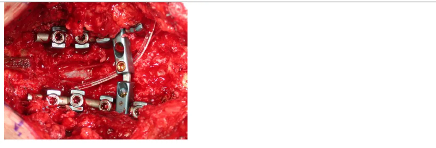
Figure 2. 13 Final screws and rods construct
Complete construct with screws, rods, nuts without their break off extension. There is a laminectomy defect in the middle. A cross link is inserted to strengthen the tortional stiffness of the construct. An epidural drain is inserted to drain excess fluid after surgery. An epidural catheter to inject Morphine is inserted under the lamina above the laminectomy for pain control.
F) Navigation concepts and surgical techniques
Since the introduction of spinal pre-operative CT-based navigation by Nolte in 1995 97,101, the principles of the technology have not change significantly. In this section the method of navigation using the SNN system (Surgical Navigation Network, Mississauga, Ontario, Canada) will be presented with case examples to illustrate the technique.
A pre-operative axial CT-Scan is performed a few weeks before the surgery using images 4mm thick with 2mm of overlap. The biomedical engineer or the navigation technician imports DICOM images on the Spinal navigation unit (SNN, Surgical Navigation Network, Mississauga, Ontario, Canada) to reconstruct a 3-D spine model, sagittal images and coronal images (Figure 2.14). Usually the day before the surgery, the surgeon plans the screw path on the navigation unit to accommodate for an entry point, the screw trajectory, the ending point (exiting point), the
screw size and the screw alignment. The surgeon can do all the planning alone, but the help of navigation specialist is valuable and time saving.
A minimum of four points are selected on images of the spine for registration during surgery. Typically six points are selected to better represent the 3-dimensional representation of the vertebra. The surgeon can use any anatomical points that have features reproducible on the image and the patient. These points need to be easily found during surgery to match image and patient co-ordinates (Figure 2.14).
Figure 2. 14 Navigation planning
a. View of the anterior spine form L2 to S1 with each vertebra reconstructed separately. The exiting points in gray (target) have
been elongated to see if the screws would interfere with the anterior approach. b. Six registration points chosen on the 3-D model (TS = top of spinous process, BS = bottom of spinous process, RTT = right top (superior) transverse process, RBT = right bottom (inferior) transverse process, LTT = left top (superior) transverse process and LBT = left bottom (inferior) transverse process. c. Both 2-D and 3-D images are used to select the navigation points.
To establish the image-patient correlation the surgeon fixes a reference frame on a spinous process above the fusion level (Figure 2.15). The reference frame has to be solidly fixed on the spine and protected from any contact by the surgical team in an effort to keep the accuracy of the navigation system.
TS BS RTT RBT LTT LBT
a
b
c
Figure 2. 15 Navigation instruments
a. The passive reference frame (patient tracker) is fixed on L3 spinous process of a sawbone and the pointer is directed laterally.
The navigation pointer is touching the left L4 transverse process. Both the reference frame and the navigation probe have their reflection spheres pointing towards the navigation camera (not shown). b. During a live L5-S1 fusion case, the passive reference frame is fixed on L4 spinous process. c. The base of the reference frame is firmly attached on a spinous process above the fusion to avoid motion of the frame. d. An active (dynamic emitting diodes) reference frame is used with similar accuracy in navigation as a passive reference frame. e. Surgical set up with dynamic reference frame. f. The assistant is showing the tracked instruments to the camera while touching the spine anatomy.
An optic camera is used as an interface between the computer system and both the reference frame and the navigation pointer. The Polaris optic camera emits and receives infrared light. The information of the location of different tools is processes in the computer system (Figure 2.16). The image of the navigation pointer is represented on the screen superimposed on the pre-operative image of the patient spine. The images of the planned procedure are also displayed on the screen to allow execution of the procedure.
The camera needs to see both navigation instruments without obstruction from the operating room personnel and equipment (Figure 2.16). Adjustments in the camera position can be done during the procedure to track the changes in position of the navigation pointer. The camera has to be able to interact with the location of three spheres at all times. The passive reference frame has three spheres that reflect infrared light. The navigation probe (pointer) has 4
a
b
c
passive reflective spheres so 3 spheres can be seen at all times. To complete the registration the pointer is used to select anatomical points on the patient previously chosen on the images (Figure 2.14).
Figure 2. 16 Spinal navigation set up
a. The set-up includes the computer system on the left, a camera that is wired to the navigation system (red arrow), a reference
frame (patient tracker) attached to the patient and a navigation pointer held by the surgeon (white arrow). b. The procedure is facilitated by navigation technician manipulating images. The images can also present on bigger screens (60 x 40 inches plasma) to facilitate the view of images by the surgeon. c. The infrared light emitted by the Polaris camera is reflected by the navigation instruments. In this case the assistant has to turn his head to see the screen. A Fluoroscopy machine was draped sterile in the operating field.
After registration of the preselected six anatomical points, an accuracy check is performed with the pointer touching any spine surfaces on the chosen vertebra (Figure 2.17). A routine for choosing surfaces is preferable to standardize the validation process and simplify the communication with the technician. The points should be chosen to evaluate a possible translation in all x, y and z axis. An error of 1mm in navigation accuracy is typically accepted in lumbar spine 22. The quest for precision is restrained by surgical time. If accuracy is not obtained, other specific points are found on both the image and the patient. The innominate process at the base of the transverse process or features on the inferior articulate process are other good anatomical points that can be used. A high quality 3-D image is important to be able to find specific anatomic points. Some newer commercially available navigation systems do not have very good 3-D images. To increase the accuracy, a surface matching technique using a minimum of 20 surface points on the flat surfaces can be used. However, this technique has not been found to be often useful 46.
Figure 2. 17 Accuracy check
a. This is a snapshot picture of the navigation screen during surgery. The navigation probe represented by a blue line is in
contact with the right transverse process. The accuracy is very good as shown by the contact of the blue line and the image of the transverse process. b. The pointer touches the superior aspect of the transverse process. c. The pointer touches the inferior aspect of the right transverse process. d. The pointer touches the right lamina. In this case, the navigation pointer is not seen because the icon of this instrument is in red (red arrow). The reference frame is seen as the PT (patient tracker icon is in green). e. The pointer touches medial aspect of the spinous process. f. The pointer touches the posterior aspect of the spinous process. The same accuracy check points are done on the left side.
When the iterative process of registration has reached a clinically acceptable accuracy, the procedure is carried out with insertion of the screws (Figure 2.18). The navigation probe is put in contact with the bone to simulate the screw trajectory. The entry point is reproduced and the bony cortex under it is drilled away with a high speed burr to expose the cancellous bone. The trajectory of the screw is then simulated with the navigation pointer (Figure 2.18). The planned trajectory is kept by the surgeon’s left hand fingers. With the right hand, the surgeon pushes the pedicle finder within the cancellous bone stopping at 40mm or less depending on the case. The pilot hole within the pedicle is sounded and the screw is inserted as described in the previous section. Small variations are sometimes found between the planned screw and the obtained screw path (Figure 2.18). If the screw has a clinically acceptable orientation, the screw is inserted following previously described techniques.
a
b
c
Adjustments with a curet to scrape the bone of the pedicle in a specific direction are sometimes necessary to readjust the trajectory. Considering that the pedicle is a tube, an alternate entry point can be used. The navigation system allows a simulation of any variations selected by the surgeon. Altering the classic entry point is often necessary at the top of the fusion to avoid the facet joint that does not need to be fused. Avoidance of the facet above the fusion is recommended to prevent post-operative adjacent level disease 92.
The screw head at the top level is brought inferiorly and laterally if muscle retraction allows this configuration. A second reason to change the classic entry point is to align all the screw heads for an easy rod insertion. A third cause of alteration in the planned trajectory is the inability to accommodate the screw trajectory due to insufficient exposure. The amount of possible muscle retraction allowed is subjectively evaluated by the surgeon during planning.
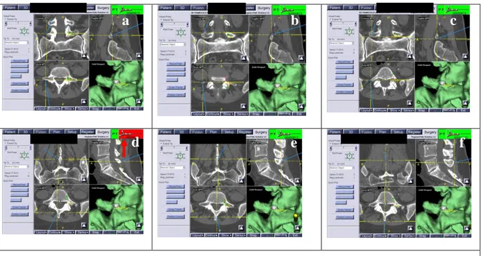
Figure 2. 18 Intraoperative navigation images
a. The right L5 screw image is showed in green and red. The yellow arrow with represent the position of the navigation probe.
With this yellow arrow there is attached a coordinate system to help the surgeon with his (her) orientation. b. The navigation probe is inserted in the pedicle to show that the trajectory created is almost similar to the screw planned. c. The entry point of right S1 screw is simulated. It is located just at the inferolateral corner of the L5-S1 facet joint. d. The navigation probe is advanced into the pilot hole to visualize the screw trajectory and the residual amount of bone left to cross for a bicortical purchase.
G) Validation and verification of the errors
As presented in the next section, errors are measured at the pedicle and at the anterior part of the vertebral body. The length errors and the pedicle medial and lateral errors are measured on axial CT-Scans (Figure 2.19). The superior and inferior pedicle errors are measured on the sagittal reconstructed images (Figure 2.19). The amount of errors is quantified in mm using the measurement tool of the Intelviewer software of the PACS system.
Figure 2. 19 Screw error assessment
a. The axial images of pedicle screws show preservation of medial and lateral pedicle walls (red arrows). The right screw is about 4
mm posterior to the anterior vertebral cortical wall (Thick red line) and the lateral vertebral body (Thin red line). The left screw is about 5mm from the vertebral anterior wall. On the sides there is morselized bone graft with adequate contact with the transverse processes. b. The Sagittal reconstruction images show intact superior and inferior pedicles at all levels. c. This is an axial image of the sacrum with bicortical screws (white arrow). On the right side of the image (left side of the patient) there is a defect in the iliac crest where a graft was resected (red arrow).
H) Assessment of bony union
A solid bony union is not always easy to define. During surgery, bone graft is inserted in the facet joints, behind the transverse processes and sometimes in the disc space. Bony union is usually assessed between the transverse processes and between the vertebrae on plain radiographs or CT-Scan. An obvious bony fusion and pseudarthrosis are easier to define (figure 2.20). In an effort to quantify good bony union from the less obvious, bony union was divided in four categories. This was classification has not been validated in the literature.
Lateral pedicle Medial Superior Inferior
a
b
c
Figure 2. 20 Bony union grading
a. Obvious bony fusion (grade 4/4). There are 2 solid bridges of bone on both sides of the spine. The superior and inferior edges
of the transverse processes are not well visible. There is no abnormal motion on flexion and extension X-rays (not shown). b. This case is probably fused (grade 3/4). The fusion mass is granulated and the superior or inferior edge of the transverse processes are visible. c. There is no bone union between the transverse processes. There is no motion on flexion and extension views. There are no signs of loosening around the screws. This is considered a fibrous union (grade 2/4). d. In this case there is a pseudarthrosis (grade 1/4). There is a hollow around the top screws (red arrow) and the allograft cage (blue arrow) does not seem to be incorporated. On AP views there is no bone mass between the transverse processes. On flexion and extension views there is no obvious motion. On CT-Scan there is widening and sclerosis of the screw tract indicating that the screws are mobile.
CHAPTER 3 – Literature Review
A) Introduction of the Literature Review
Computer-aided image-guided surgery has improved accuracy and safety of spinal fusion 47. Spinal navigation and image-guided spinal surgery are accepted terminology used for this application.
Spinal navigation has its origins in cranial applications. David Roberts 127 in 1986 created for cranial surgery a stereotaxy system without a frame which used ultrasounds as the medium of transmission. Frameless image guided surgery using preoperative CT-Scan images were developed in early 1990’s. Initially, both electromagnetic and optical cameras were used, but current technology has moved towards optics.
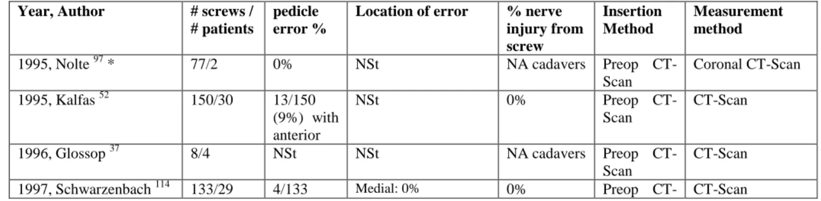
Nolte introduced the use of spinal CT-based navigation to the spine in 1995 97,101. Since then, pre-operative CT-based navigation principles did not change significantly. The literature on CT-CT-based navigation shows a misplaced screw rate varying between 4 and 7% 8,52,53,70,84, as measured by postoperative CT- Scans. Computer-aided image guided surgery, has significantly improved the accuracy and safety of routine and complex spinal instrumentation procedures 47. CT-based navigation, though accurate, is time consuming, needing the difficult process of registration of the vertebra. CT-based navigation is not adequate for the newer percutaneous procedures as registration points need to be taken on the anatomy of the patient.
Other technologies such as 2D-fluoroscopy, 3D-fluoroscopy, operative CT-Scan, 2D-3D registration and intra-operative ultrasound registration of pre-intra-operative CT-Scan, are being developed to avoid the step of manual registration. Robots have also been used for pedicle screw insertion. Different techniques of spinal navigation have been developed in this fast-evolving domain.
In this chapter, the literature related to pedicle screw instrumentation and navigation techniques will be presented. For most sections, a table is presented to summarize the results.
B) Radiological Evaluation of Error
A uniform way to communicate the errors should be used to facilitate comparison between series. The error can be measured at the pedicle level or at the vertebral body level. The pedicle error is usually described anatomically following four quadrants: medial, lateral, superior or inferior (Table 3.1). The vertebral body error is less frequently reported and is usually described by the presence or absence of breach of the vertebral body anteriorly. The optimal screw length is controversial so an error length was less systematically studied. Errors have significance if they are associated with a worse clinical outcome. Some errors have been associated with bad consequences 10,32,115 but most series had 0% nerve root injuries. In a case of misplaced screw, it is not always easy to associate the screw error with a clinical radiculopathy.
Different tools to measure errors were used in the literature: plain radiographs, axial CT-Scan, sagittal CT-Scan, coronal CT-Scan 53,96. In 1976, Saillant was the first to use X-Rays to report errors in pedicle screw insertion 77. In one report, radiographs were successful in determining the position of the implant in only 41% of the cases 8. In 1999, Sapkas 109 prospectively evaluatated the radiography and CT-Scans of 35 patients following lumbar and thoracic screw insertion. CT-Scans showed that 4% of the 220 screws were outside the pedicle, contrary to 1% with plain radiographs. Questionable screws were found in 2.5% of CT-Scans and in 3% of plain radiographs. In 1997, Yoo defined CT-Scan a sensitivity of 86%, a specificity of 88% and an accuracy of 87% to predict titanium pedicle screw misplacement. In the literature, CT-Scan was in general more reliable than radiographs to detect pedicle screw
errors 123. CT-Scan is considered the gold-standard in evaluating the pedicle screw error 25,131. In our study we use axial and sagittal CT-Scan to evaluate the screw misplacements.
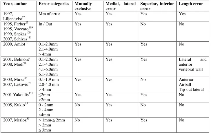
In a meta-analysis completed in 2007, Kostmopoulos found 35 different methods to define pedicle screw error 61. The most frequently used method is in or out of the pedicle. The second most used method is to define the pedicle error in 2 mm increments. The Gertzbein method 32 has 6 categories: no pedicle breach, 0-2 mm medial pedicle breach, 2.1-4 mm medial pedicle breach, 4.1-6 mm medial pedicle breach, 6.1-8 mm medial pedicle breach and a lateral pedicle breach. The lateral error was not quantified and was not defined as in or out of the pedicle. There was no description of superior of inferior errors. This method is based on the anatomical observation that there is 2mm of epidural space between the pedicle and the neural structures and 2mm of arachnoid space form T10 to L4 32. Gertzbein wrote that 4 mm of canal encroachment can be tolerated without risk of the spinal cord or cauda equina injuries 32. This 4 mm space was called the “safe zone” 32 . This can also be called the “tolerance zone”. Laine 71 (1991) used 2 mm increment measurements to define errors medially and laterally.
Ideally, the reporting method chosen should use mutually exclusive measures and avoid overlapping ranges (eg: 0-2, 2-4 and 4-6 mm). This classification is based on the anatomical measurements of epidural space. Reynolds measured the right lateral epidural space from T7 to L4 to be 2.4mm +- 0.2mm and the left side 2.3mm +- 0.2mm 105. Values with 1 mm increments can have statistical advantages but this method was not widely used in the
literature.
Some studies included the impression of the surgeon about the strength of screw purchase 10,102,106. In pedicle precision studies, such subjectivity cannot be used to compare studies.
In our study we used a similar 2mm increment method of measuring the error in all 4 quadrants of the pedicle (medial, lateral, superior and inferior). We used axial and sagittally reconstructed images as per our radiology
department protocol. Coronal images or images perpendicular to the axis of the pedicle were not part of our protocol.
Table 3. 1 Methods of measurement of errors Year, author Error categories Mutually
exclusive Medial, lateral error Superior, inferior error Length error 1997, Liljenqvist77
Mm of error Yes Yes Yes Yes
1995, Farber25 1995, Vaccaro119 1999, Sapkas109 2007, Schizas111
In / Out Yes Yes No No
2000, Amiot 1 0.1-2.0mm 2.1-4.0mm > 4mm
Yes Yes Yes No
2001, Belmont7 2008, Modi91 0.1-2.0mm 2.1-4.0mm 4.1-6.0mm 6.1-8.0mm
Yes Yes Yes Lateral and
anterior vertebral wall 2003, Mirza88 2007, Lekovic76 0.1-1.9 mm 2.0-4.0 mm > 4mm
Yes Yes No Anterior
Airball Tip-out lateral 2001 Yakoulis131 ≤2mm
>2mm
Yes Yes Yes No
2005, Kuklo65 0 - 2mm 2 - 4mm >4mm No Yes No No 2007, Merloz85 > 1mm-≤ 2mm > 2mm ≤ 3mm No Yes Yes No
C) Anatomical Landmarks and/or Intraoperative Fluoroscopy
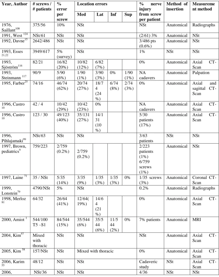
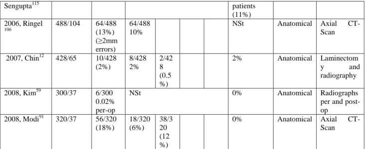
Most surgeons use anatomical landmarks (topography, free hand), with or without fluoroscopy, for screw insertion. Earlier series reported pedicle screw perforation in the range of 40% (table 3.2). With increased experience, lower rates of pedicle screw injuries were reported. Recent studies only rarely report high rates of errors and nerve injuries 115.
Data from table 3.2 (see below) shows that lumbo-sacral screws inserted using anatomic (free-hand) methods, with or without fluoroscopy, have a pedicle perforation rate varying from 0.2% - 62%. Studies that used only X-Rays
for post-op evaluations, reported a perforation rate that varies from 0.02% to 5%. In studies using Axial CT-Scans for post-op evaluations, the perforation rate varied from 13-62%. The higher rates of perforation are found in studies reporting also the superior and inferior errors. The nerve root injury rate varied from 0-17% in these series and
occurred more often when the screw error was ≥5mm. Following a misplaced screw, patients usually present with a
new onset of leg pain and more rarely with weakness or drop foot. As an alternative to landmarks, surgeons have used the palpation of the pedicle after laminectomy as another way to try to improve screw accuracy. This technique was not found to significantly increase the error rate.
In 1990, Gertzbein 32 used Axial CT-Scans to report pedicle screw perforation. The authors used lateral fluoroscopy to help guide the alignment of the screws. The authors saw an improvement in the screw error rate over time, showing a learning curve. By extracting lumbo-sacral screw data from their tables, we found the errors were mostly medial (25%) and classified as such: 9% (0-2 mm), 9% (2.1-4.0 mm), 4% (4.1-6 mm), 2% (6.1-8.0mm). Only 3% of errors were laterally position to the pedicle. Only one patient, with a screw inserted 7 mm medially into the canal, developed a nerve root injury with paresthesia in L2 distribution.
In the thoracic spine, screws evaluated with CT-Scan have a pedicle error rate that varies from 2% to 41% (Table 3.3). Unfortunately some authors choose to exclude small errors from 0 to 2mm. As most errors occur in that zone, the real pedicle rate is not accurately stated. The reported rate only reflects large errors that have the potential of causing neurological injuries.
The results of thoracic screws in Gertzbein’s were also extracted from their tables. The authors inserted 71 thoracic
pedicle screws 32. After analyzing their data, 26% of screws were too medial (0-2mm = 7/71, 2.1-4.0 mm = 6/71, 4.1-6.0 mm = 4/71 and 6.1-8.0mm). Only 4% of screws (3/71) were too lateral. It is not clearly stated if the second patient with neurological injury was in the thoracic group. One patient had headaches that lasted 2-3 days. There was no spinal cord compression in this group.
Table 3. 2 Literature review for lumbo-sacral pedicle error with landmarks, radiography and fluoroscopy insertion techniques
Year, Author # screws / # patients
% error per screw
Location errors % nerve injury from screw per patient Method of insertion Measureme nt method Med Lat Inf Sup
1976, Saillant108 375/56 10% NSt NSt Anatomical Radiographs 1991, West 124 NSt/61 NSt NSt (2/61) 3% Anatomical NSt 1992, Davne15 2642/486 NSt NSt 3/486 pts (0.6%) Anatomical NSt 1993, Esses 21,22 3949/617 5% (survey) NSt 1% NSt NSt 1993, Sjöström116 82/21 16/82 (20%) 10/82 (12%) 6/82 (7%) 0% Anatomical Axial CT-Scan 1993, Steinmann 117 90/9 5/90 (6%) 1/90 (1%) 3/90 (3%) 0% 1/90 (1%) NA cadavers Anatomical Palpation 1995, Farber25 74/16 46/74 (62%) 20/74 (27%) 18/7 4 (24 %) 6/74 (8%) 2/74 (3%)
0% Anatomical Axial and
sagittal CT-Scan 1996, Castro 10 42 / 4 10/42 (29%) 10/42 (23%) 0% NA cadavers Anatomical Axial CT-Scan 1996, Castro 10 123 / 30 49/123 (40%) 35/131 (27%) 14/1 31 (10 %) 5/30 patients (17%) Anatomical Axial CT-Scan 1996, Pihlajamaki99 NSt/63 NSt NSt 3/63 patients NSt NSt 1997, Brown, pediatrics9 759/223 2/759 (0.2%) 2/759 (0.2%) 2/223 patients (1%) 6/759 screws (1%) Anatomical NSt 1997, Laine 71 35 / NSt 5/35 (14%) 3/35 (9%) 1/35 (3%) 1/35 (3%) 0% 1/35 screws (3%) Anatomical Coronal CT-Scan 1999, Lonstein79 4790/NSt 5% NSt 0.2% Anatomical Radiographs 1998, Merloz 81 64/32 26/64 (41%) 12/64( 19%) 14/6 4 (21 %) 0% Anatomical Axial CT-Scan 2000, Amiot 1 544/100 T5 –S1 84/544 (15%) 35/544 (6%) 35/5 44 (6%) 11/5 44 (2%)
0% 7% patients Anatomical MRI
2004, Kim57 Mixed with thoracic
NSt NSt NSt Anatomical Axial
CT-Scan
2005, Kim 58 157/NSt NSt Mixed with thoracic 0% Anatomical Axial
CT-Scan 2006, Karim 55 48/12 NSt NSt Cadaveric study NSt Axial CT-Scan 2006, NSt/36 NSt NSt 4/36 NSt NSt