Science Arts & Métiers (SAM)
is an open access repository that collects the work of Arts et Métiers Institute of Technology researchers and makes it freely available over the web where possible.
This is an author-deposited version published in: https://sam.ensam.eu Handle ID: .http://hdl.handle.net/10985/14795
To cite this version :
Nadja GAUDILLIÈRE, Romain DUBALLET, Charles BOUYSSOU, Alban MALLET, Philippe ROUX, Mahriz ZAKERI, Justin DIRRENBERGER - Building Applications Using Lost Formworks Obtained ThroughLarge-Scale Additive Manufacturing of Ultra-High-Performance Concrete - 2019
Any correspondence concerning this service should be sent to the repository Administrator : [email protected]
CHAPTER 3
Building Applications Using Lost
Formworks Obtained Through
Large-Scale Additive
Manufacturing of
Ultra-High-Performance Concrete
N. Gaudillière1,2, R. Duballet1,3, C. Bouyssou1, A. Mallet1, Ph. Roux1, M. Zakeri1and J. Dirrenberger1,4
1XtreeE, Rungis, France
2Laboratoire GSA, Ecole Nationale Supérieure d’Architecture Paris-Malaquais, Paris, France 3
Laboratoire Navier, UMR 8205, Ecole des Ponts, IFSTTAR, CNRS, UPE, Paris, France
4Laboratoire PIMM, Arts et Métiers-ParisTech, Cnam, CNRS UMR 8006, Paris, France
3.1 INTRODUCTION
Until recently, additive manufacturing (AM) techniques were confined to high value adding sectors such as the aeronautical and biomedical indus-tries, mainly due to the steep cost of primary materials used for such processes. In the past decade, there has been development of large-scale AM in such domains as design, construction, and architecture by using various materials such as polymers, metals, and cement[1].
Historically, the first attempt at cement-based AM was made in 1997
[2] using an intermediate process between the classical powder bed and inkjet head 3D printing (3DP)[3] and fused deposition modeling (FDM)
[4] in order to glue sand layers together with a Portland cement paste. Many groups have been involved with the development of large-scale AM for construction applications, all of which have been using processing routes derived from FDM or 3DP, although these vary depending on the chosen material and targeted application.
The aim of this chapter is to shed a new light on the perspective of 3D concrete printing in the construction industry, specifically using the lost formwork technique, by describing three case studies based on actual
building projects performed using the XtreeE1 3D concrete printing sys-tem. InSection 3.2, an introduction on designing structures for large-scale AM is given. In Section 3.3, the concrete formwork 3D printing tech-nique is presented, followed by three case studies demonstrating the potential advantages of this technique for the construction industry. In
Section 3.4, conclusions are drawn regarding the results obtained.
3.2 DESIGN FOR ADDITIVE MANUFACTURING
Generating and modeling shapes for AM follows specific rules from both processing constraints and functional objectives. According to Ref. [1], the concept of freeform previously used in the literature is not adequate or sufficient for describing 3D concrete printing. For a given printing pro-cess and automation complexity, one can attain specific types of topolo-gies within a given time-frame and performance criterion for the structure. Although out of the scope of this chapter, design conditions for large-scale AM depend on many other parameters than merely the prop-erties of extruded cementitious materials, such as the printing spatial reso-lution, overall size of parts to be printed, the environment, and the presence of assembling steps, etc. A tentative classification of such relation-ships between geometrical complexity, processing, and design is proposed in Ref.[5].
Processing constraints depend mostly on the fresh material properties in their viscous state as well as early-age behavior in the interaction with the building strategy and the stiffness of the structure being built, as reviewed in Ref. [11]. On the other hand, functional requirements will depend on the properties of the hardened material, the structural geome-try for effective stiffness, and other functional properties such as thermal and sound insulation. See Ref. [1] for a geometrically induced thermal insulation case study. Both types of constraints have to be considered at the design stage.
Printing path generation is a critical step during the design phase. There are two main approaches to tool-path generation in the context of 3D printing: (1) 3D-to-2D slicing, by far the most common method adopted, yields planar layers of equal thickness built on top of each other. This approach is not optimal from the design and structural viewpoints as it will induce cantilevers when two consecutive layers have different sizes
1
and limit the attainable geometries; and (2) the tangential continuity method introduced in Ref. [1] in order to optimize the structure being built by creating layers of varying thickness. These layers exhibit a maxi-mized surface area of contact between each other, hence stabilizing the overall structure. Moreover, this method actually exploits the possibilities of the process in terms of printing speed and flow for generating variations in the layer thickness. As of 2017, the tangential continuity method is no longer available in commercial software packages.
Along with the paradigm shift of AM comes the possibilities enabled by topology optimization, which aims at attaining the most efficient struc-ture geometrically possible for a given set of requirements. Optimality in terms of industrial design has become more and more critical due to the scarcity of material resources and the need for lightweight structures. This technique has become well-established in the field of structural mechanics, especially when associated with finite element simulation. Classical meth-ods, such as Solid Isotropic Material with Penalization (SIMP[6]) rely on node-based values to evaluate and optimize the geometry, that is, the number of design variables is equal to the number of elements available in the model at initialization. Then, the optimization procedure consists of determining at each element whether it should either remain as a material element or become a void element, that is, be removed. This technique has been applied to different scales; for instance with regards to the design of efficient building structures [7], or as a tool for designing micro- and nanoarchitectured materials[8].
A driving force for AM is its ability to produce more complex 3D shapes in comparison with casting or subtractive processes. This complex-ity allows us to design optimal structures based on topology optimization techniques. One of the main challenges currently is to modify optimiza-tion algorithms in order to account for the AM constraints, especially with regards to the processing parameters and structural stability while printing. A possible solution to these challenges would be to consider the multiphysics phenomenon aspect of 3D printing which involves the elastic stability of the overall structure being built, the kinetics of hydration, the evolving viscoplasticity of fresh cement, and the evolution of temperature within the printing environment, etc. All these physical problems, at mul-tiple time and space scales, can be modeled on their own, but coupling them generates complexity and uncertainty regarding the process of 3D printing. Therefore, efforts should be concentrated on understanding and modeling the printing process for its multiple physical aspects, only then
can optimization will be fully integrated with the processing, which would change the way 3D-printed structures are conceived today.
In order to fully exploit the potential of AM technologies in construc-tion, various alternative ways have been explored regarding the building process—as done, for instance, in Refs. [1,9] for varying layer thickness and multifunctionality, and in Ref.[10]for the case of 3D-printing-aided robotic assembly for spatial structures. In this chapter, the path of concrete formwork 3D printing is explored in the light of several applications in architecture and construction.
3.3 CONCRETE FORMWORK 3D PRINTING
The process of large-scale 3D concrete printing developed by XtreeE has been presented in Ref.[1]. The overall process is summarized inFig. 3.1.
Based on this process, a construction strategy can be derived for con-crete formwork 3D printing. The principle consists in only 3D printing the formwork that is necessary for casting another structural material, such as ultra-high-performance concrete (UHPC) for fiber-reinforced concrete, or insulation material such as foamed concrete, in order to build multi-functional components, as shown on Fig. 3.2. The printed formwork is left inplace and becomes a lost formwork. An optimal tradeoff has to be taken into account from the early design steps concerning the ratio of printed material within the built part, which can be critical for reaching economic viability. Depending on the application considered, concrete formwork 3D printing can be more efficient than either all-3D concrete printing, or traditional building techniques, from both an economic and/ or building strategy viewpoint. This assertion is demonstrated in the next three sections using different case studies.
3.4 CASE STUDY 1: POST IN AIX-EN-PROVENCE, FRANCE 3.4.1 Context
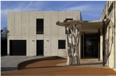
This 4 m-high freeform pillar is placed in the sports facilities of a school in Aix-en-Provence, France. It supports a concrete awning covering part of the playground, as shown in Fig. 3.3. The sports facilities project was mandated by the Aix-Marseille Metropolis. The pillar, part of this larger project, was handled by: Marc Dalibard as the architect (also the architect for the whole sports facilities building), Artelia as the structural engineer-ing office, AD Concept as the construction company, LafargeHolcim as
Figure 3.2 Schematic view of the concrete formwork 3D printing. Figure 3.1 Workflow of the large-scale concrete 3D printing process.
the material supplier, and Fehr Architectural as the UHPC concrete caster. For the construction of the pillar, the responsibilities of the actors were divided: Marc Dalibard was also the manager of the overall project and defined the shape and placement of the pillar. Artelia supported XtreeE both during design and construction phases and was tasked with defining the load case on which to base the topological optimization and verifying the strength and stability of the printed pillar in accordance with the load case. LafargeHolcim supplied a specific 3D printing concrete, developed with XtreeE in an earlier collaboration. Fehr Architectural casted UHPC inside the pillar, a task requiring a specific license. Each one of the key players supported XtreeE in the definition of the fabrication strategy adopted for the pillar by providing inputs regarding their field of expertise.
XtreeE identified a fabrication strategy for the post and adapted the printing system developed earlier (presented inSection 3.3) according to the fabrication strategy and its requirements. During the design stages, XtreeE codefined the load case for the topological optimization with structural engineer Artelia and designed an exact shape for the pillar through the optimization. In the fabrication stages, XtreeE coded the manufacturing files for the printing system and performed the manufacturing before cosupervising the placing of the pillar on site with Dalibard.
3.4.2 Design
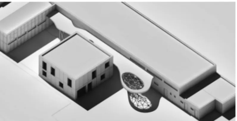
In the initial project designed by Dalibard, a complex truss-shaped pillar supporting the roof was already planned as shown on Fig. 3.4. But, although the idea of a complex truss-shaped pillar was featured, no viable design for the pillar existed at this stage of the project. XtreeE came in at this point and took over the design of the pillar, based on the sketches provided by Dalibard.
The design of the pillar is based as much on the formal intention highlighted in the sketches as on the constraints fixed by the building regu-lations in effect at the time and by the 3D printing manufacturing method.
As no building regulation existed regarding 3D-printed items inte-grated into buildings at the time of construction and in order to stick to the projected schedule, the choice was made to use the lost formwork manufacturing method, as introduced in Section 3.3. Instead of having to validate the pillar and its manufacturing method by using an Experimental technical appreciation (ATEx), a long and expensive procedure for experi-mental construction in France, the lost formwork made it possible to rely on existing building regulations for UHPC concrete.
For the 3D printing system developed by XtreeE, the main limitation encountered for complex truss shapes, such as the pillar, is the maximal inclination attainable for a given geometry. In the case of the Aix-en-Provence pillar, this issue was avoided by printing supports at the same time as the sought-after geometry, in order to enable any angle to be printed.
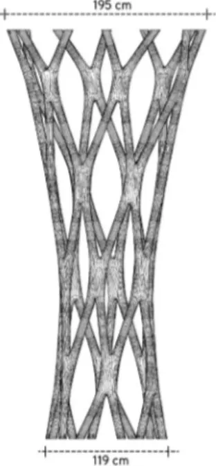
To define the precise shape of the pillar, we relied on a topological optimization method to ensure optimal use of matter in the truss. The entire circular volume containing the pillar is used as research space for
the truss to develop, and the applied load case included the weight of the concrete awning supported by the pillar as well as site-specific constraints (wind, etc.). The resulting final shape is shown in Fig. 3.5. A more thor-ough examination of the possibilities offered by topology optimization in the context of 3D concrete printing is available in Ref.[10].
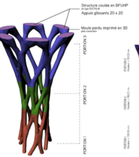
Given the selected approach of lost formwork printing, the pillar was made of an outer shell that was 3D-printed and later filled with UHPC. The 3D-printing system in place at the time at XtreeE did not allow for printing the outer shell in one piece. Therefore, the pillar was divided in three smaller parts (cf. Fig. 3.6), each one to be filled with concrete and then assembled together to form the whole element. During casting, metallic female connectors were inserted in the concrete at each end of the parts. Male plugs were then used to connect the different parts of the pillar and assemble them.
3.4.3 Manufacturing
The manufacturing of the pillar included three stages: 3D-printing of the outer shell at XtreeE’s headquarters in the south of Paris, France; casting the UHPC and integrating the connectors at the Fehr Architectural pro-duction facility in the north of France; and final assembly onsite in Aix-en-Provence. 3D-printing the outer shell inside the facility allows, like for UHPC casting, a precise control and monitoring of the environment, to ensure ideal temperature and humidity conditions for the concrete to behave as expected.
As a precaution, after running trials on smaller geometries similar to the pillar, it was decided to 3D-print the formwork in four parts rather than three. The concrete formwork took 15 hours to print, that is, approximately 3 hours and 45 minutes for each part of the post. Setting time was typically comparable to the setting time of C60 concrete, that is, about 2 hours. Once the formwork was successfully 3D-printed, an assembly trial was conducted at our facility to ensure the results were as precise as expected before shipping the parts to the site.
The casting of UHPC in each part of the pillar was then operated by the team from Fehr Architectural. To resist the hydrostatic pressure result-ing from the castresult-ing, supports printed with the pillar were left in place until the UHPC set. The supports were then removed, as shown in
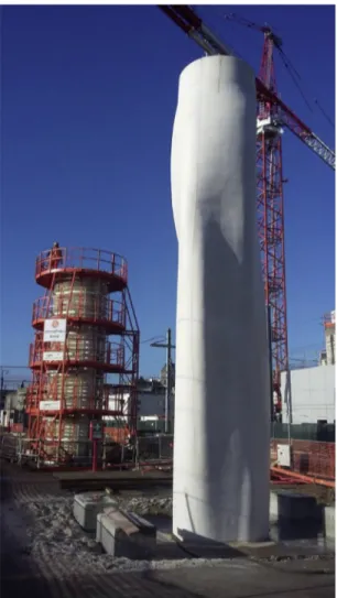
Fig. 3.7, and the parts were shipped to the site in Aix-en-Provence. The definitive assembling of the parts was performed there, before installing
the pillar in place with sliding supports on top and at its feet. Finally, on request of the architect, the pillar was given a smooth finish by coating it to cover the line pattern specific to 3D-printed objects. The difference of surface roughness is shown inFig. 3.8.
Figure 3.7 Cast and lost formwork assembly from which the printing supports were cut.
Figure 3.8 Before (left) and after (right, photo by Lisa Ricciotti) surface smoothing obtained through manual coating.
3.4.4 Comparison to Standard Building Methods
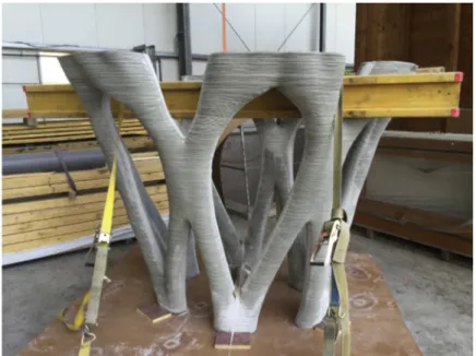
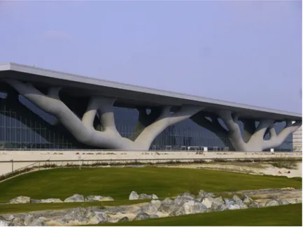
After completing the Aix-en-Provence pillar project, we conducted a study to compare our process for complex truss-shaped pillars fabrica-tion to standard building methods. Two types of pillars were com-pared: a traditionally built pillar with a complex shape and geometry comparable to the Doha Convention Center pillars as shown in
Fig. 3.9, but in a smaller scale; and a more complex pillar, in terms of shape, built with the AM lost formwork technique, such as the Aix-en-Provence pillar. The building process and gain in terms of material, build time, and workforce for both types of pillar is illustrated in
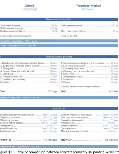
Fig. 3.10. The data for 3D printing is based on the experience gained from the Aix-en-Provence pillar project, while the data for the tradi-tional casting technique using steel molds is based on realistic values for implementation in the same socioeconomic environment, that is, Western Europe. It is noteworthy that the actual cost of steel molds has not been considered although it is likely to be the most costly aspect of a traditional casting technique. Even without considering the molds, concrete formwork 3D printing emerges as a cost-effective alternative for pillar construction.
It could be interesting, as well, to further compare 3D-printed pillars with lost formwork to traditionally built pillars of semistandard shapes, such as the Nantes train station pillars depicted inFig. 3.11.
The table presented in Fig. 3.10 highlights the potential gain from several viewpoints, some being more significant than others. Another element of comparison can be given by considering the total produc-tion price of the Aix-en-Provence pillar in relaproduc-tion to the total
Figure 3.10 Table of comparison between concrete formwork 3D printing versus tra-ditional concrete casting in steel molds.
production price of a traditionally built complex pillar: a 62.5% total price gain is obtained, based on our information for the price of the Aix-en-Provence pillar and quotes obtained for a traditional manufacturing. One of the main reasons for this price difference (on top of the gain identified on time, materials, and workforce) is the absence of a specific material and shaping for the mold, hence elimi-nated by using the lost formwork method. Furthermore, comparison with the Nantes train station pillars, cost brings to light the fact that
Figure 3.11 Example of semistandard shaped pillar on the construction site of the new train station of Nantes, France.
prices become comparable when building at least 18 identical pillars with a traditional-mold manufacturing method.
The Aix-en-Provence pillar has also provided input on possible improvements for the lost formwork method, including getting rid of the supports by advancing the development of a 3D-printing system, gather-ing each of the manufacturgather-ing stages (i.e., 3D-printgather-ing, castgather-ing, assem-bling) at the same place to reduce transportations, as well as setting up construction regulations for 3D-printed concrete structural parts.
3.5 CASE STUDY 2: YRYS CONCEPT HOUSE IN ALENÇON, FRANCE
The YRYS Concept House was developed by Maisons France Confort (one of the largest individual house constructors in France) to support and implement various innovations in building methods. The YRYS Concept House has been designed to experiment new building solutions for a more environmentally friendly, evolutive, and adaptive housing. Among the 18 partners taking part in the construction of the project, XtreeE was tasked with designing and 3D-printing four pillars and an interior separa-tion wall for the house.
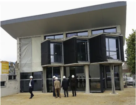
The four pillars were placed in the exterior and support part of the upper floor, as shown in Fig. 3.12. The design and manufacturing method is similar to the Aix-en-Provence pillar, with adjustments made in accor-dance to the size of the pillars, which are smaller than the Aix-en-Provence pillar, to the load case, which is heavier than the Aix-en-Provence pillar, and in accordance with the inputs provided by the Aix-en-Provence project for the improvement of the lost formwork method.
The four pillars were each divided into two parts for easier transporta-tion and for more rapid printing. The eight formwork parts were printed in a row, next to each other, as shown in Fig. 3.13. As the pillars were only divided into two parts and are significantly smaller in diameter than the Aix-en-Provence post, with less assembly points, they were not assembled with metallic connectors and/or plugs. The two 3D-printed shells of each pillar were stacked before UHPC casting, which yielded structural continuity for the pillar (cf. Fig. 3.14). The assembled pillars were finally brought onsite and placed.
The wall is an interior separation partition between the stair’s circula-tion area and the main room. The use of 3D-printed lost formwork allows for a perforated design with a nonrepetitive pattern. This
Figure 3.12 Exterior pillars supporting part of the upper floor on the YRYS Concept house in Alençon, France.
manufacturing method also allowed for the efficient production of such perforated concrete partitions as only the contour was printed (cf.
Fig. 3.15), and the body itself was then cast inside the contour, used as lost formwork. The same manufacturing stages that were implemented for the pillars were used to produce the wall: 3D-printing the formwork in our facility, shipping the parts on site, casting concrete, finishing, and finally placing the elements on the construction site, as shown in
Fig. 3.16.
The YRYS Concept house pillars and interior wall produced by the concrete formwork 3D printing technique present comparable time,
material, and workforce efficiency potential as the Aix-en-Provence pillar. Moreover, it has also been an opportunity for implementing some of the improvements considered following the previous project. In particular, casting onsite has allowed a significant reduction in transportation costs and the geometry of the pillars allowed for their printing without supports to be removed afterwards.
Figure 3.15 3D-printed concrete formwork for the YRYS Concept house interior wall.
Figure 3.16 Interior wall made of the 3D-printed concrete formwork filled with cast concrete after finishing.
3.6 CASE STUDY 3: RAIN COLLECTOR IN LILLE
As part of a long-term collaboration with Point P TP, the French leader in construction materials distribution, we developed a process for the design and manufacturing of rain collectors. As rain collectors should be implemented underground on the city’s drainage network, rapidity of execution is a priority for cities in order to avoid blocking the streets for a long period of time due to construction. Nevertheless, manufacturing rain collectors in the traditional way requires blocking the circulation, digging into the ground to take measurements, building adequate casing, casting, curing, setting the concrete, and, finally, rehabilitating the road. This lengthy process can be drastically improved by using the 3D-printing, lost formwork technique.
This first rain collector, measuring 2.153 2.2 3 2.6 m, was manufac-tured in partnership with Point P TP and Sade, a utility network-specialized company located in Lille, France. XtreeE developed the design with Point P TP in order to fit the site constraints, such as the placing of pipes connected to the collector, as well the 3D-printing constraints. The rain collector features a 3D-printed concrete shell with a sinusoidal ele-ment inside. The sine part, developed in former projects as a way to
reduce thermal bridges (see Ref.[1]), also works as a stiffener element for the two external parts of the shell. The whole structure was printed within 9 hours, as shown in Fig. 3.17, directly on a reinforced concrete slab designed to support the lifting and placing operations of the collector onsite (cf.Fig. 3.18).
A comparison between the rain collector produced by XtreeE and the traditionally produced rain collectors was performed on three aspects based on the data supplied by Point P TP: material, time, and workforce-gain potential. The details and results are presented inFig. 3.19.
3.7 CONCLUSIONS AND OUTLOOK
The various advantages of large-scale AM of ultra-high-performance con-crete, as well as the concrete formwork 3D printing technique, are reviewed in this chapter based on the analysis of three case studies taken from industrial construction projects in France which were performed using the XtreeE 3D-printing technology. The multiple aspects of the potential socioeconomic gain for relying on AM are threefold: (1) materi-als saving by using the right amount of matter where needed, given that a
Figure 3.19 Table of comparison between concrete 3D printing versu. traditional on-site casting for rain collectors.
multiobjective topology optimization computational framework is avail-able; (2) time-saving by reducing the number of steps in the construction process, as well as being building information model-compatible for construction-planning strategies; and (3) workforce saving by limiting onsite manual building steps, therefore, enhancing safety on the construc-tion site.
Although the lost formwork strategy allowed to get around experi-mental technical certification, further work should have to be conducted with certification authorities for the construction industry in order to define a legal and regulatory framework for 3D-printed structures. The technological feats presented in this work are commercially available, but a legal framework and an anaylsis of the economic market need to be developed in order for the 3D-printing technology to be transferred into the mainstream construction industry.
REFERENCES
[1] C. Gosselin, R. Duballet, P. Roux, N. Gaudillière, J. Dirrenberger, P. Morel, Large-scale 3d printing of ultra-high performance concrete a new processing route for architects and builders, Mater. Des. 100 (2016) 102 109.
[2] J. Pegna, Exploratory investigation of solid freeform construction, Autom. Constr. 5 (1997) 427 437.
[3] E. Sachs, J. Haggerty, M. Cima, P. Williams, Three-Dimensional Printing Techniques, 1993.
[4] S. Crump, Apparatus and Method for Creating Three-Dimensional Objects, 1992. [5] R. Duballet, O. Baverel, J. Dirrenberger, Classification of building systems for
con-crete 3d printing, Autom. Constr. 83 (2017) 247 258.
[6] M. Bendsøe, O. Sigmund, Topology Optimization, Springer, 2004.
[7] C. Cui, H. Ohmori, M. Sasaki, Computational morphogenesis of 3d structures by extended eso method, J. Int. Assoc. Shell Spatial Struct. 44 (1) (2003) 51 61. [8] S. Zhou, Q. Li, Design of graded two-phase microstructures for tailored elasticity
gradients, J. Mater. Sci. 43 (2008) 5157 5167.
[9] R. Duballet, C. Gosselin, P. Roux, Additive manufacturing and multi-objective optimization of graded polystyrene aggregate concrete structures, in: M. Thomsen, M. Tamke, C. Gengnagel, B. Faircloth, F. Scheurer (Eds.), Modelling Behaviour-Design Modelling Symposium, 2015, Springer, 2016.
[10] R. Duballet, O. Baverel, J. Dirrenberger, Humanizing Digital Reality, Chapter Design of Space Truss Based Insulating Walls for Robotic Fabrication in Concrete, Springer, 2018, pp. 453 461.
[11] R.A. Buswell, W.R. Leal de Silva, S.Z. Jones, J. Dirrenberger, 3D printing using concrete extrusion: a roadmap for research, Cement and Concrete Research 112 (2018) 37 49.