Science Arts & Métiers (SAM)
is an open access repository that collects the work of Arts et Métiers Institute of
Technology researchers and makes it freely available over the web where possible.
This is an author-deposited version published in:
https://sam.ensam.eu
Handle ID: .
http://hdl.handle.net/10985/14416
To cite this version :
Luis PALLARES-SANTASMARTAS, Joseba ALBIZURI, Alexander AVILES, Nicolas SAINTIER,
Jonathan MERZEAU - Influence of mean shear stress on the torsional fatigue behaviour of
34CrNiMo6 steel - International Journal of Fatigue - Vol. 113, p.54–68 - 2018
Any correspondence concerning this service should be sent to the repository
Science Arts & Métiers (SAM)
is an open access repository that collects the work of Arts et Métiers ParisTech
researchers and makes it freely available over the web where possible.
This is an author-deposited version published in:
https://sam.ensam.eu
Handle ID: .
http://hdl.handle.net/null
To cite this version :
Nicolas SAINTIER - Influence of mean shear stress on the torsional fatigue behaviour of
34CrNiMo6 steel - Influence of mean shear stress on the torsional fatigue behaviour of
34CrNiMo6 steel - Vol. 113, p.54-68 - 2018
Any correspondence concerning this service should be sent to the repository
In
fluence of mean shear stress on the torsional fatigue behaviour of
34CrNiMo6 steel
Luis
Pallarés-Santasmartas
a,⁎,
Joseba Albizuri
a,
Alexander Avilés
b,
Nicolas Saintier
c,
Jonathan
Merzeau
ca Department of Mechanical Engineering, Escuela de Ingeniería de Bilbao, University of the Basque Country, Alameda de Urquijo s/n, 48013 Bilbao, Spain b Advanced Design & Analysis, IDOM Engineering & Consultancy, Avenida de Zarandoa, 48015 Bilbao, Spain
c École Nationale Supérieure d'Arts et Métiers ParisTech à Bordeaux-Talence, Esplanade des Arts et Métiers – 33405, Talence Cedex, France
A R T I C L E I N F O
Keywords: Torsional fatigue Mean stress effect Haigh diagram Multiaxial fatigue criteria
A B S T R A C T
This study provides a theoretical and experimental investigation of the effect of static shear stresses on the high-cycle fatigue behaviour of a 34CrNiMo6 high-strength steel under quenched and tempered conditions. Torsion S–N curves under different mean shear stresses were obtained. Experimental results show that an increase in mean shear stress yields a gradual reduction in shear-stress amplitude that the material can withstand without failure. The results for this steel agree well with the Smith’s hypothesis for ductile steels, which states that the effect of the torsional mean stresses on the torsional fatigue limit is negligible as long as the maximum shear stress is within the torsional yield strength. Taking into account the results collected from the literature and the experimental results on torsional fatigue of 34CrNiMo6 steel, an extension of the theory of Crossland is proposed to include the mean-shear-stress effect. Its application to the torsional fatigue case with mean shear stresses can be interpreted in terms of a balance of the energy of distortion. Macro-analyses of the specimen fracture ap-pearance were conducted to obtain the fracture characteristics for different mean-shear-stress values under torsion fatigue loading.
1. Introduction
An analysis of the available literature, which includes modern books on fatigue[1–4], shows that the effect of mean torsional stresses on the fatigue strength is still a controversial issue in the engineering world, and that no unified view exists on its influence, despite the different experimental campaigns that have been performed[5–30]. In any case, it can be said that this influence is less pronounced than for mean axial stresses, especially for ductile materials.
The pioneering experimental campaigns of torsional fatigue with mean shear stresses were performed by McAdam[5]and Moore and Jasper[6,7]amongst others in the 1920s. McAdam found that the mean shear stress could be neglected without important errors, and proposed a constant-range Eq.(1): = − − τ τ R 2· (1 τ) max 1 (1) Moore and Jasper[6,7]took advantage of their own experimental campaign to conclude that the repeated torsional fatigue limitτ0is 1.93 times the fully reversed torsional fatigue limit τ−1. This means a
decrease of 3.5% in fatigue strength for a repeated torsional fatigue loading compared with the fully reversed torsional loading, leading to a weak effect of the mean shear stresses on the torsional fatigue limit.
In 1939, Smith[8]performed tests on two SAE 3140 steels, and confirmed the validity of Eq.(1)for results within the static torsional yield strength. Smith presented a model tofit the data, and included tests beyond the torsional yield strength, through linear Eq.(2), which predicts a 6.25% decrease in fatigue strength for the repeated torsion case (Rτ= 0). = − + τ τ ·(7·R 15) 8 τ max 1 (2) In 1942, Smith[9]published a large database of torsional tests with a mean shear stress that was collected from the literature that was available at that time. This collection consisted of 27 different ductile materials, including different types of steel, malleable iron, aluminium alloys, bronze, brass and cooper. The results showed that the effect of mean shear stress is negligible for tests in which the maximum shear stress was less than 80% of the torsional yield strength. The author attributed the scatter in data beyond 80% of the torsional yield strength
https://doi.org/10.1016/j.ijfatigue.2018.04.008 ⁎Corresponding author.
E-mail address:luispallares.bilbao@gmail.com(L. Pallarés-Santasmartas).
to different methods that were used by the investigators for its de-termination, and concluded that the results supported the conclusion by precedent authors such as McAdam, that the mean torsion stress does not influence the torsional fatigue strength, provided the static shear yield stress τyp is not exceeded during cyclic loading. The method proposed in this paper agrees well with this hypothesis. Smith’s work has influenced later works extensively, as summarised by Sines[31], who is cited by Papadopoulos et al.[32]to have stated that the effect of
mean shear stress is negligible for fatigue lives above 106cycles, where the fatigue limit usually occurs, provided that the torsional yield strength is not exceeded. For lower fatigue lives, the slope of the tor-sional fatigue line in a Haigh-likeτm–τadiagram is negative. This hy-pothesis is in accordance with Eq.(1)for the case of the fatigue limit, and is represented schematically inFig. 1a[32].
In the late 1940s and early 1950s, several investigators performed multiaxial fatigue campaigns, including torsional fatigue loading with static shear stresses [10–12], which led them to conclude on the in-fluence of mean shear stresses, even below the torsional yield strength.
Fig. 1b illustrates the results obtained by Findley[12]for an aeronautic aluminium. Two different domains can be identified: an approximately linear influencing region in the elastic domain, which is the slope of the Haigh diagram in torsion, which is nearly constant with the number of
cycles, even for fatigue lives above 106cycles; and a non-linear region above the elastic domain with a stronger influence of mean shear stress. It should be noted that this aluminium alloy appears not to have the pseudo-fatigue limit below 108cycles.
In 1956, in the context of the 1st International Conference of Fatigue, Findley[33]and Marin[34]proposed their multiaxial fatigue methods, which take into account the effect of mean shear stresses. Findley took into account all previous performed tests, and assumed that the influence of mean stress is small for torsion and stronger for the bending and axial of ductile metals, but strong for the torsion, bending and axial of cast irons. Marin presented his method with an extensive multiaxial fatigue database, including 289 strength values from 23 series of tests, and obtained an average standard deviation of only 3.6% between experimental and theoretical values. The fatigue group of the University of Bristol presented results of a complete fatigue campaign on En25T NiCrMo steel. Chodorowski[13]presented on a campaign of torsional fatigue with mean torsional stresses, and concluded that the effect occurs even below the torsional yield strength. Crossland[35]
presented on the torsional fatigue strength of the same En25T steel with high hydrostatic pressures, and presented a linear function of the von Mises stress amplitude that was corrected with maximum hydrostatic stresses, whichfitted the results of axial fatigue with mean axial loads Nomenclature
R fatigue ratioσmin/σmax Rτ torsional fatigue ratioτmin/τmax σuts ultimate tensile strength τuss ultimate shear strength
τusss estimated ultimate shear strength
σyp axial yield strength τyp torsional yield strength
Mσ mean axial stress sensitivity index Mτ mean torsional stress sensitivity index
λF 1st parameter of Findley's critical plane method βF 2nd parameter of Findley's critical plane method σa amplitude of axial fatigue stress
σm mean component of axial fatigue stress τa amplitude of torsional fatigue stress τm mean component of torsional fatigue stress
τmin minimum value of torsional fatigue stress τmax maximum value of torsional fatigue stress σ−1 fully reversed axial fatigue limit
τ−1 fully reversed torsional fatigue limit τ0 repeated torsion fatigue limit
κ ratio of fully reversed axial and torsional fatigue limits σ−1/τ−1
N life (number of cycles to failure) ∗
τa amplitude of shear stress in the critical plane
∗
Nmax maximum normal stress to the critical plane
A elongation at fracture (%)
Z reduction in area (%)
N number of cycles
ktt stress concentration factor in torsion J2 second invariant of the stress deviator tensor WD elastic energy of distortion
a. Sines–Papadopoulos hypothesis [32],
b. experimental results by Findley [12]
and torsional tests with hydrostatic stresses. Crossland admitted in a subsequent discussion [36]that the mean-shear-stress effect on the
torsional fatigue strength was demonstrated clearly and conclusively for thefirst time by Chodorowski[13], and remarked on the need for an extension of the theory that he had proposed to include the mean-shear-stress effect and to take into account the anisotropy.
In the 1970s and 1980s, large campaigns of multiaxial fatigue were conducted in Germany [15–19], which lead to the conclusion of the influence of mean torsional stresses. In consequence, several methods were proposed, including this effect, such as those of Grubi-sic–Simbürger[37]and Liu–Zenner[38]amongst others. Modern de-sign rules, such as the FKM Guideline [39,40], include the effect of mean shear stresses in torsional fatigue. The effect for ductile steels is approximately 58% of the effect of axial static stresses in the pure axial fatigue loading case. This is expressed through Eq.(3), which presents the relationship between the slopes of the Haigh diagram axial and the torsional diagrams, Mσand Mτrespectively:
=
M M
3
τ σ
(3) A mean stress sensitivity that is higher in axial than in torsion was also reported by Findley[24], and in a recent paper by Mayer et al.[41]
for a VDSiCr spring steel. The results in torsion for the latter report could befitted by the Gerber line in the Haigh torsional diagram[23]. More methods were developed in the 1990s and 2000s, including the mean-shear-stress effect, such as that by Robert [42], which de-velops the critical plane of Findley; Froustey–Lasserre[43], which is based on the total energy approach; and the critical plane of Papuga
[44], which is based on empirical considerations. In a recent review of multiaxial fatigue methods[45], the methods which take into account the effect of the mean shear stresses have a better experimental agreement with the tests with static torsional stresses than those methods which neglect the effect.
Other investigations related to the torsional fatigue have been per-formed in the recent years. There is currently intense research on the effect of mean stress in notched components[46,47]. Moreover, nu-merous investigations have been performed in the torsional fatigue of
steel wires[48–50].
The objective of this study is to determine the torsional fatigue behaviour of a 34CrNiMo6 steel with a tensile strength of 1210 MPa and a tensile yield strength of 1084 MPa, to provide a fatigue model for torsional fatigue with mean shear stresses. A review from relevant re-sults of the literature gives support to the idea that the mean shear stress effect is not negligible in ductile metals, but it is less pronounced than the mean axial stress effect. A torsion test campaign on 34CrNiMo6 steel was conducted with different combinations of static and variable shear stresses, and the results were compared with the predictions from the multiaxial fatigue criteria. The experimental re-sults on torsional fatigue show that the mean shear stress effect cannot be neglected, especially when the maximum yield strength is exceeded. Finally, taking advantage of the formulation of the proposed torsional fatigue modelling, a multiaxial fatigue criterion is developed as an improvement of the Crossland method to take into account the mean shear stress effect.
2. Review of relevant results from the literature
The effect of mean torsion in the torsional fatigue limit is reviewed and summarized next. A detailed study of the available literature results allows for a determination of the range of validity of classic hypotheses, which states the non-influence of mean shear stresses in the torsional fatigue strength (as long as the maximum shear stress is within the torsional yield strength) and is used by the mesoscopic methods of Dang Van[51]and Papadopoulos[52]. The mean stress effect in torsion of
ductile and fragile materials is compared with the mean stress effect in uniaxial fatigue to determine if the hypotheses that were followed to derive the Findley critical plane method[53]were correct. Moreover, this study will allow for conclusions to be inferred regarding the shape of the Haigh torsional diagram and modelling through classic lines that were used in uniaxial fatigue.
Following the trend of other authors such as Smith[9]and Davoli et al.[22], the results have been plotted in a normalized maximum stress versus alternating stress diagram. In this type of diagram, the maximum shear stress of the cycleτmaxis expressed as a fraction of the
Fig. 2. Normalized maximum shear stress-alternating shear stress diagram, 25 steel and aluminium alloys represented[6–23]and the 34CrNiMo6 of this work.
static torsional shearing yield strengthτyp, and is plotted as an abscissa, and the alternating shear stressτais expressed as a fraction of the fully reversed fatigue limitτ−1and is plotted as an ordinate.
Ninety experimental results for 26 different steels and aluminium alloys with unnotched specimens for lives above 106cycles have been collected, including all the experimental results known by the authors, which are represented inFig. 2. This database includes the pioneering extensive campaign of Moore and Jasper[6,7]and the results by Smith
[8]. It also includes results of ductile materials [10–12], which are taken into account to develop the well-known methods of Marin and Findley and the results by Chodorowski [13], which are considered definitive proof of the influence of the mean shear stress even below the torsional yield strengthτyp. Newer results have been included in the database, some of which have not appeared in a comparison of torsional experimental results[14–15,17–18,21,23], and the results of this ex-perimental campaign are also included.Fig. 2supports the conclusion inferred by Smith, as the effect of mean shear stresses is, in general, low for maximum shear stresses below 80% of the τyp. The extension of Smith’s conclusion for the 100% of τypappears to be doubtful because of the number of tests in which the torsional fatigue strength decreases. Smith's hypothesis is fulfilled for the steel that was analysed here (yellow dots inFigs. 2 and 3), with less than 1% error.
Some authors, such as Findley[53], considered that the conclusion stated on the non-influence of the mean shear stresses on the torsional fatigue strength was influenced by the plotting method based on the maximum stress-alternating stress diagram. The fully reversed torsional fatigue limit is usually 2/3 of the torsional yield strength[25], which, in general, is quite close to 80% of the torsional yield strengthτyp, so few tests have been performed below the torsional yield strength. The results of the fully reversed torsional are usually included in the dia-gram[9,22], and provided that these tests represent a great percentage of the number of points that are represented below the torsional yield strength, the visual appearance of the non-influence of the mean shear stresses below the torsional yield strength is increased.
The normalized τm–τadiagram inFig. 3 shows the experimental results of ductile materials for which the maximum shear stress is within the torsional yield strength. This reappraisal of the diagram of
Fig. 2suggests that, in general, the fatigue strength in torsion tends to decrease slightly with an increase in mean stresses. For the 25 torsion fatigue tests with non-zero mean shear stresses in which the maximum shear stress is below the torsional yield strength, the fatigue strength was increased only in two tests, whereas in 23 other tests, the influence of mean shear stress had a detrimental effect.
For the uniaxial case, the results are usually plotted in a Haigh diagram, in which the mean axial stressσmis normalized with the ul-timate tensile strengthσuts. Some authors use a torsional Haigh diagram in which the mean torsional stress is normalized in terms of the ultimate torsional strengthτuss. For instance, in a recent paper, Mayer et al.[23] found that the mean-shear-stress effect on a VDSiCr spring steel could be modelled through Gerber's parabola in the torsional Haigh diagram. The same idea was proposed by Sauer[6]in 1948 for a 14S-T alumi-nium alloy. Both experimental results are presented in a normalized Haigh torsional diagram inFig. 4. The Gerber line, Eq.(4), shows a horizontal slope in the intersection with the axis of ordinates, which suggests that the effect of mean shear stresses is negligible for low va-lues, and increases progressively for higher mean shear stresses.
⎜ ⎜ ⎟⎟ = ⎛ ⎝ −⎛ ⎝ ⎞ ⎠ ⎞ ⎠ − τ τ τ τ · 1 a m uss 1 2 (4) The elliptical relationship for torsion, represented in Eq.(5), shows also a horizontal slope in the intersection with the axis of ordinates. The mean shear stress effect is less pronounced than the one predicted by the Gerber line.
⎜ ⎟ = −⎛ ⎝ ⎞ ⎠ − τ τ τ τ · 1 a m uss 1 2 (5) The Goodman line for torsion, Eq.(6), represents a linear influence of the mean shear stress on the torsional fatigue strength.
⎜ ⎟ = ⎛ ⎝ − ⎞ ⎠ − τ τ τ τ · 1 a m uss 1 (6) The complete database is plotted in a normalized Haigh diagram,
Fig. 6. For some steels, in which the τuss value is unavailable, the
estimated static shear strengthτusss was calculated by means of Eq.(7),
based on the collection of data analysed by Smith[5]: ≈
τusss 0.75σ
uts (7)
In the Haigh torsional diagram (Fig. 5), 53.4% of the data lie be-tween the Gerber and Goodman lines, and the remaining 46.6% lies
over the Gerber line. No result lies below the Goodman line. However, for the uniaxial Haigh diagramσm–σa, some authors[54]have found that∼90% of the results lie between the Gerber and Goodman lines. This will lead to the conclusion that the mean stress effect is lower in torsion than in axial for ductile materials.
For fragile materials, Findley[53]considered that the
mean-shear-Fig. 4. Normalized torsional Haigh diagram with the experimental results of a 14S-T aluminium alloy[10]and a VDSiCr spring steel[23].
stress effect is as important as the mean axial loads for the uniaxial case. To test this hypothesis, eight different cast irons have been collected from the literature[9],[26–30], and have been represented inFig. 6. The estimated ultimate torsional strength is approximately equal to the ultimate tensile strength, as the Worst Principal Stress criterion is ful-filled[55]. This can be represented through Eq.(8):
≈
τusss σ
uts (8)
For the cast irons, some of the results lie below the Goodman line. Smith’s conclusions in[9]remark on the great impact of mean torsional stresses in fragile materials. The Smith line, Eq.(9)was recommended for design purposes. The same line was recommended for the axial fa-tigue. = − + −
(
)
(
)
τ τ · 1 1 a τ τ τ τ 1 m uss m uss (9)Therefore, it can be concluded that the mean stress effect is lower in torsion than the axial mean stress effect for ductile materials, but is strong in torsion and axial for cast irons, which are considered to be fragile materials.
3. Effect of mean shear stress in multiaxial fatigue theoretical models
Amongst the multiaxial fatigue methods, the Marin[34]method, which is based on stress invariants; the Findley [33] critical-plane method and the energetic approach that is based on the method of Froustey–Lasserre [43]will be considered. These methods take into account the effect of mean shear stresses in the torsional fatigue case, and can be expressed easily through analytic formulations for the tor-sion case.
The Marin method[34]is based on stress invariants, and can be
expressed through Eq.(10):
⎛ ⎝ ⎜ ⎞ ⎠ ⎟ +⎛ ⎝ ⎜ ⎞ ⎠ ⎟ ⩽ − J σ J σ 3 · 3 · 1 a m uts 2, 1 2 2, 2 (10) where√J2,a and√J2,mare the amplitude and the mean value of the square root of the second invariant of the stress deviator, andσ−1is the fully reversed fatigue strength in bending or tension. For pure torsion tests, it can be expressed as follows:
⎜ ⎟ ⩽ −⎛ ⎝ ⎞ ⎠ − τ σ τ σ 3· 1 3 · a m uts 1 2 (11) As given by Eq.(11), the Marin method is sensitive to the mean shear stress, and is represented by an ellipse in the Haigh torsional diagram. The von Mises relationship is conserved; therefore, the ratio between the fully reversed axial (σ−1) and the fully reversed torsional fatigue limit (τ−1) is equal to√3, which is not verified experimentally for this steel. The fully reversed axial fatigue limitσ−1of this steel has been determined in an axial fatigue campaign through a staircase method according to ISO 12107:2012[56]with a step of 10 MPa, and a value ofσ−1= 615 MPa has been obtained[57]. Therefore, the fatigue ratioκ = σ−1/τ−1is equal to 1.42.
The Findley method[33]is a critical plane approach that is based on the plane that maximises the damage function as given by:
= ∗ + ∗
f ϕ θ( , ) τa ( , )ϕ θ α NF· max ( , )ϕ θ (12)
Once the pair of angles (φ∗, θ∗) have been obtained for which this function is a maximum, the fatigue indicator parameter as given by Eq.
(10)is computed, whereαFandλFare material parameters that can be identified from endurance fatigue limits, and are usually the fully re-versed axial and torsional fatigue limits (σ−1andτ−1).
∗ ∗ ∗ + ∗ ∗ ∗ ⩽
τa ( , )ϕ θ α NF· max ( , )ϕ θ λF (13)
Findley's method can be applied analytically to pure torsion tests (14): ⩽ + − − + τ λ α λ α τ α τ α · · 1 a F F F F m F m F 2 2 2 2 2 2 2 (14) The constantsαFandλFdepend on the value of the fatigue ratioκ = σ−1/τ−1. Whenκ is equal to 2.0, which corresponds to the Tresca criterion,αFbecomes 0.0, so that the mean shear stresses produce no effect on the torsional fatigue strength. For materials that follow the Rankine maximum principal stress criterion, that is: κ ≈ 1, the pre-dicted influence of the mean shear stress is very high. This theory ex-plains the fact that the influence of mean stress is small for the torsion of ductile metals, but is strong for the torsion of cast irons.
The Froustey and Laserre method[43]is based on energetic con-siderations. When this method is applied to the pure torsion case, analytic Eq.(15)is derived:
⎜ ⎟ ⩽ −⎛ ⎝ ⎞ ⎠ − τ τ κ τ σ · 1 · a m uts 1 2 (15) Eq.(15)is an ellipse in the Haigh torsional diagramτm–τa. A visual inspection of the terms indicates that the derived formula is similar to that of Marin, but the experimental fatigue ratioκ is taken into account instead of the von Mises relationship.
Some methods do not take into account the mean shear stress effect, as the Crossland stress invariant method[35], and other methodologies such as the ones based on the mesoscopic theory, namely the Papado-poulos integral method[52]and the Dang Van critical plane method
[51].
4. Testing procedure 4.1. Material
The material that was used in this fatigue campaign was high-strength 34CrNiMo6 steel that was provided by Thyssen–Krupp in 30-mm cross-section diameter forged bars. The heat treatment consisted of normalization at 900 °C, followed by quenching in oil and tempering at 570 °C. The resulting microstructure was ductile-tempered martensite. The certified chemical composition is presented in Table 1. The monotonic mechanical properties of this steel are given inTable 2, and show a ductile behaviour.
This steel shows a homogenous microstructure that is comprised of fine tempered martensite, with a banded orientation of the inclusions in the longitudinal section that are not visible in the transverse section (Fig. 7a and b). As it was observed in other previous investigations related to the 34CrNiMo6 steel, porosity and many inclusions of man-ganese sulphide and alumina with different sizes were found[58,59], being round-shaped and small, with maximum defect size equal to √area ≈ 5 µm.
4.2. Specimens and testing machine
Fatigue tests were performed on standard hourglass specimens whose dimensions are given in Fig. 8. Hourglass-shaped specimens were chosen because this geometry allows for the concentration of failures in a limited specimen area and reduces the scatter. Similar specimens have been used in previous campaigns in quenched and tempered steels, as in[22]. The value of the stress concentration factor in torsion kttis lower in this case than in the cited campaign, and a value of ktt= 1.03 has been obtained according to the Peterson for-mulas for stress concentration[60].
The specimens were manufactured according to the recommenda-tions of ASTM E-466[61]. After the machining processes, the following residual stresses were measured at the surface of the machined speci-mens: −340 MPa in the tangential direction and −280 MPa in the
longitudinal direction. The machined specimens were subjected to a stress-relieve heat treatment at 190 °C for 24 h to reduce residual stresses that were induced by machining, following the procedure of Nascimento et al.[62]to avoid Tempered Martensite Embrittlement (TME). This stress relieving process allowed to reduce the residual stresses of the machined specimens to−250 MPa in the tangential di-rection and −220 MPa in the longitudinal direction. These stresses disappear within 10 µm in depth direction. The final process was a conventional polishing with progressively finer emery papers from P800 to P4000, to obtain a mirrorfinish. The residual stresses of the polished specimens were measured at the surface, taking a value of −30 MPa in the longitudinal and tangential directions. A final average roughness Ra = 0.03 µm was measured.
Fatigue tests were performed in the laboratories of the ENSAM at the Bordeaux campus (France), on a servo-hydraulic bending-torsion fatigue machine with multiple actuators, a maximum available torque of 150 N·m and at 50 Hz. This testing machine was used previously in other multiaxial fatigue campaigns, such as those of Froustey–Lasserre.
[63].
The bending moment was controlled during the tests and was set to 0.0 N·m to ensure that the loading case was pure torsion. The run-out wasfixed at 2 × 10⁶cycles, according to the recommendations for this type of steel[64]. The failure criterion was defined as a 10% loss in specimen rigidity, as was conducted in other similar campaigns of torsional fatigue with mean shear stresses[22]. This enabled the test to be interrupted with cracks of an approximately 0.5-mm depth on 10-mm-diameter specimens.
5. Results and experimental correlation with multiaxial fatigue models
5.1. Fatigue test results
A fatigue campaign of torsional fatigue withfive levels of mean shear stresses has been performed, namelyτm= 0, 150, 250, 350 and 500 MPa, with a total number of 83 specimens considering all the tests. Tests were stopped at a maximum fatigue life of 2 × 10⁶cycles, based on the recommendations for the number of cycles of the fatigue limit for this type of steel[64]and a previous campaign of a similar material
[24]. The inclined part of the S–N curves and the subsequent staircases
were determined following the ISO standard method[56]. This proce-dure enables to optimise the number of specimens, so that thefirst run-out for the inclined part of the S-N curve can be used to start the staircase process. For the superimposed static shear stress of τm= 500 MPa, the slope of the S–N curve was nearly horizontal, so testing was limited to the staircase. InFig. 9, the S–N curves are
pre-sented, and show a measurable effect of the mean shear stresses for the entire fatigue-life range: 5 × 10⁴< N < 2 × 10⁶cycles.
Based on the recommendations of previous campaigns [12], the staircase for the fully reversed torsional fatigue limit τ−1 was per-formed with a higher number of specimens, as such data are usually used to adjust the multiaxial fatigue methods, and therefore they are convenient to reduce the uncertainty. The obtained values of the tor-sional fatigue strengths at 2 × 10⁶cycles are shown inTable 3.
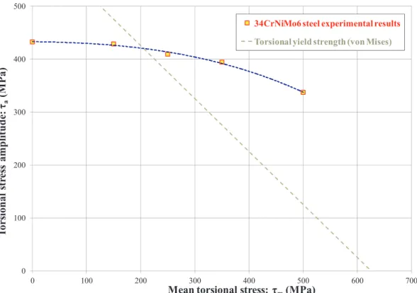
The results for 2 × 10⁶cycles are plotted in a Haigh torsional dia-gram,Fig. 10, and are interpolated through a polynomial line. The results show that the effect of the mean shear stresses is negligible as long as the maximum shear strengthτmaxis below the torsional yield strengthτyp. The results show a convex upward function in the Haigh
Table 1
Chemical composition of 34CrNiMo6 steel (at.%).
C Si Mn P S Cr Mo Ni Fe
torsional diagram.
5.2. Fractographic analysis of the specimens
Fractographic analysis is not essential for the quantitative purposes of this work, but it allows for an observation of the planes of failure and the nature of the fatigue failure. As usually observed in the high cycle fatigue region[22], crack initiation occurs at the very late stage of the fatigue life: a macroscopic crack was not observed until very few cycles before thefinal fracture. The number of initiated cracks increased with the level of cyclic torsional stresses. For instance, three or more in-itiated cracks existed for shear stress amplitudes that are equal to or higher than 480 MPa, irrespective of the mean shear stress that is ap-plied.
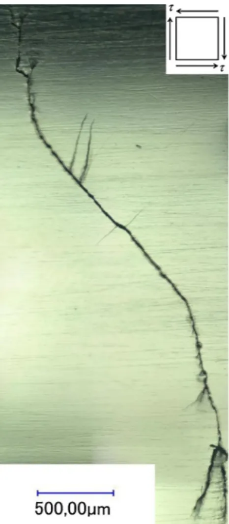
Crack nucleation occurred in planes near the maximum shear stress planes for mean shear stresses up to 350 MPa, with maximum angular deviations of 15° (Fig. 11). The cracks can be propagated in the max-imum normal or maxmax-imum shear stress planes, irrespective of the mean shear stress that was applied. The phenomenon of crack branching was also observed.
However, a different pattern occurred for the 500-MPa mean-shear-stress loading case: in some specimens, the observed macroscopic crack was placed near the maximum principal stress plane (Fig. 12). This observation can be explained through the aid of the mean shear stress in Mode I; stage-II crack growth has already been observed by other in-vestigators[25], and is caused by an increase in maximum plastic zone size.
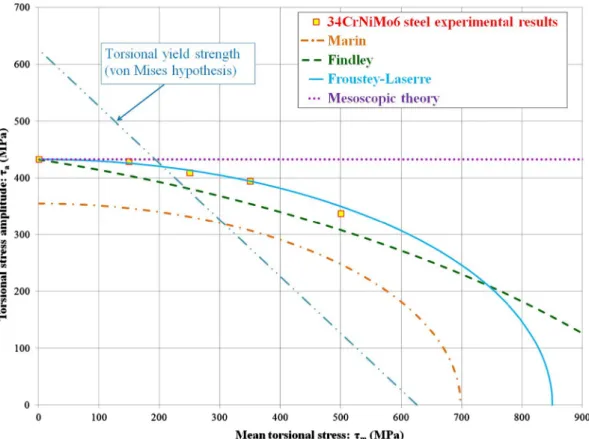
5.3. Correlation of the experimental results with multiaxial fatigue theories InFig. 13, the different predictions are represented in a Haigh
tor-sional diagram with the experimental results. InTable 4, the relative errors (%) of the different theories are presented for N = 2 × 10⁶ cy-cles. As observed, the Froustey–Lasserre method yields the best agree-ment with the experiagree-mental results from the selected methods. Marin's
method shows a conservative behaviour because the von Mises re-lationship is not verified. Findley's method overestimates slightly the detrimental effect of the mean shear stresses for three out of four tests, which show good agreement with the experimental results and an error below 5%. The methods that not dependent on the mean shear stress effect, such as the Crossland method and the methodologies based on the mesoscopic approach, namely, the Dang Van[51]critical plane, or the Papadopoulos[52]integral method, agree for the only testing result below the torsional yield strength. For this case, the response is similar to the energetic method of Froustey–Lasserre, as claimed in [65]. However, the error increases for high mean torsional stresses. 6. Development of a multiaxial fatigue criterion for a 34CrNiMo6 steel
6.1. Modelling of torsional fatigue with mean torsional stresses
An ellipse in the Haigh torsional diagram thatfits the results of 34CrNiMo steel can be expressed through Eq.(16), which is a mod-ification of the Marin criterion. In Eq.(16),“a” and “b” are constants whose values are the longitudes of the vertical and horizontal axis, respectively, of the ellipse that is drawn in the Haigh torsional diagram τm–τa. ⎛ ⎝ ⎜ ⎞ ⎠ ⎟ +⎛ ⎝ ⎜ ⎞ ⎠ ⎟ = J a J b 1 a m 2, 2 2, 2 (16) Eq.(16) meets the condition for isotropic materials, that is, the polarity of the mean shear stress has no influence, which results in a symmetrical Haigh torsional diagram. This equation can be explained in terms of a balance of energy of distortion: The elastic energy of dis-tortion WDis proportional to the second invariant of the stress deviator tensor J2. Therefore, Eq.(16)equalizes the energy that is stored for the static torsional loading to the fatigue torsional loading, where“a” and “b” are constants of the material. The constants “a” and “b” of Eq.(16)
represent respectively the alternating and static von Mises stress at which the material fails[34]. The values of the constants“a” and “b” can be determined by means of two different torsional fatigue tests, namely the fully reversed and repeated torsional fatigue limits,τ−1and τ0, as explained in Appendix A: Derivation of the parameters.
However, Eq.(16) is not suitable for a general multiaxial fatigue loading, as it is not sensitive to the hydrostatic stresses, and predicts a similar influence of the mean shear and mean axial stress effects, which is not in agreement with the experimental results for ductile materials in the literature.
Table 2
Monotonic mechanical properties of 34CrNiMo6 steel.
Monotonic properties Symbol Value
Ultimate tensile strength σuts 1210 MPa
Yield strength σyp 1084 MPa
Elongation at fracture A 12.2%
Reduction of area Z 60.2%
a. Longitudinal section
b. Transverse section
6.2. Extension of the Crossland method to take into account the mean shear stress effect
The Froustey–Lasserre method offers excellent agreement for this ductile material in the torsional fatigue loading case with mean shear stresses. However, its application to axial fatigue loading with mean axial stresses yields a symmetrical Haigh diagramσm–σa. It is accepted in the literature that the Haigh diagrams are non-symmetrical, with an increasing trend for the mean compressive stresses due to the effect of the hydrostatic stresses. The application of Eq.(16)to the uniaxial case results in a symmetrical Haigh diagramσm–σa, which contradicts the experimental results for most ductile steels[57,66]. Moreover, Cross-land [35] demonstrated that mean compressive hydrostatic stresses benefited the torsional fatigue limit, and he proposed a linear function to model their effect.
According to the conclusions of the extensive review of the multi-axial fatigue methods performed by Papuga[45], the mean stress effect is the most important factor in determining the accuracy of a multiaxial fatigue method. As mentioned in[35], Crossland remarked on the need for an extension of the theory that he had proposed to include the
Fig. 8.“Hourglass” specimen used in torsional fatigue tests. Dimensions in millimetres.
Fig. 9. S–N curves with different levels of mean shear stress. Table 3
Obtained torsional fatigue strengths at 2 × 10⁶cycles.
τm (MPa) τa (MPa) Standard Deviation (MPa) No. specimens (staircase)
0 432.5 7 15
150 428.6 5 7
250 409.1 7 7
350 394.3 3 7
mean-shear-stress effect. The Eq.(16)can be modified by adding the
maximum hydrostatic stressσH,max, to take into account the beneficial effect of the compressive hydrostatic stresses. The extension of the Crossland method to take into account the mean shear stress effect is expressed by means of Eq.(17):
⎛ ⎝ ⎜ ⎞ ⎠ ⎟ +⎛ ⎝ ⎜ ⎞ ⎠ ⎟ + = J a J b σ c 1 a m H 2, 2 2, 2 ,max (17) Eq.(17)conserves the linear influence of the maximum hydrostatic
stress on the von Mises stress amplitude, and takes into account the
mean-shear-stress effect.
The determination of the parameters can be done with 3 different tests in order to determine the 3 constants“a”, “b” and “c”. The values of the constants“a” and “b” can be adjusted by means of two different torsional tests, as there are no hydrostatic stresses involved in the pure torsion tests. The value of the constant“c” can be adjusted by using another test in which the maximum hydrostatic stress takes a non-zero value, as the fully reversed axial fatigue limitσ−1. The algebraic de-termination of the values of the constants“a”, “b” and “c” is presented in Appendix A, and their values shown in Eqs.(18a)–(18c):
= − a τ 1 (18a) 0 100 200 300 400 500 0 100 200 300 400 500 600 700
T
or
sio
nal s
tr
es
s
am
pli
tude
: IJ
a(M
Pa
)
Mean torsional stress: IJ
m(MPa)
34CrNiMo6 steel experimental results
Torsional yield strength (von Mises)
Fig. 10. Torsional Haigh diagram with the experimental results at 2 × 10⁶cycles.
Fig. 11. Surface crack patterns in the failed specimens: (a)τa= 440 MPa;τm= 0 MPa; Ncycles = 1,026,120, (b)τa= 430 MPa;τm= 150 MPa; Ncycles = 812,704,
= − −
( )
b τ 2 1 τ τ 0 2· 0 1 (18b) = − − c σ κ 3 3 · 1 (18c) The proposed method is applied to the 34CrNiMo6 steel, and the parameters for this material are shown inTable 5. The application of the method presented in Eq. (17) to the Haigh torsional diagram is represented inFig. 14and in the Haigh axial diagram inFig. 15, to-gether with the experimental results in torsion and axial fatigue loading. InTables 6 and 7, the relative errors of the proposed method are presented for the torsional and axial fatigue loading cases respec-tively.The proposed method predicts an asymmetric shape in the Haigh diagram (Fig. 15), with an increase in fatigue strength for low to medium values of mean axial compressive stresses, and a decrease of the fatigue strength for tensile mean loads, giving support to the modelling based on the detrimental effect of the maximum hydrostatic stresses proposed by Crossland.
Moreover, by adding the maximum hydrostatic stress term in the proposed multiaxial damage function, the mean stress effect is in-creased in axial compared with the torsion case, which explains why the effect of mean stress is higher in the axial and bending directions than for torsion of ductile materials. This result has been documented in
the review of the experimental results.
Although the proposed function(17)has been developed and ver-ified experimentally for the 34CrNiMo6 steel, it could be used for other isotropic ductile materials. Its application should be limited to isotropic materials in the range that is defined by other authors for Crossland-based methods[32], 1.25 <κ < √3, which includes mild steels and low-alloy steels[67]and aluminium alloys. A large database of mate-rials with the values of theκ ratio can also be found in[45]. The upper limit of the proposed method arises because, in the von Mises re-lationship (κ = √3), the method becomes the Marin function, which was devised for materials where there was no effect of hydrostatic stresses. For a lower fatigue ratio κ, the theoretical influence of the hydrostatic stresses increases, which increases the effect of mean axial stresses but preserves the low influence of the mean shear stresses, as demonstrated in the review of the experimental results on steels and aluminium alloys. Sines [31]states that, for very low fatigue ratios (approximatelyκ < 1.25), which correspond to materials with large defects, such as cast irons[9,26–30], and cast aluminium alloys[68,69]
the nature of the fatigue failure changes, and the failure can be de-scribed through a maximum normal stress criterion. As shown in the review of the experimental results on cast irons, the effect of the mean shear stresses is strong for materials with large defects, and the pro-posed function will underestimate the mean-shear-stress effect for this type of materials.
Finally, from a computational cost point of view, it can be said that this method, which pertains to the class of the stress invariants methods, is one order of magnitude less demanding than the critical plane methods in terms of computational cost, and two orders of magnitude when compared to the integral methods[70].
7. Conclusions
The detrimental effect of the mean shear stresses on torsional fa-tigue strength is measurable for the studied range of fafa-tigue life, be-tween 50,000 and 2 × 10⁶ cycles. Mean shear stresses had a minor impact on the torsional fatigue strength at 2 × 10⁶ cycles of the 34CrNiMo6 steel as long as the maximum shear stress was below the torsional yield strength. In fact, the experimental points that represent the fatigue strength at 2 × 10⁶cycles as plotted in the Haigh torsional diagram show a nearly horizontal slope for the intersection with the axis of ordinates (Fig. 10).
The invariants-based method of Marin[34], the critical-plane-based criterion of Findley [33], and the energetic method of
Froustey–-Lasserre[43]were compared with the experimental results. The Marin method showed a conservative behaviour (19–26.5% of error), whereas the Findley criterion was slightly conservative, with a mean value of the error of 7.9%. The energetic Froustey–Laserre method showed excellent agreement for all tests, with a mean value of the error of 1%. The methods that were based on the mesoscopic approach, which are in-dependent of the mean shear stress, exhibit a similar behaviour to the energetic approach as long as the maximum shear stress is below the torsional yield strength, which confirms the statements of Morel et al.
[65]. The agreement of the methods of Papadopoulos and Dang Van is excellent (error < 1%) for the only loading case (τm= 150 MPa) in which the yield strength is not exceeded.
The experimental results on torsional fatigue show that the mean shear stress effect cannot be neglected, especially when the maximum yield strength is exceeded. The mean shear stress effect can be modelled with the elliptical relationship shown in Eq.(16). The physical inter-pretation of the proposed model to deal with mean shear stresses is a balance of the energy of distortion. The resulting Haigh torsional dia-gram is an ellipse, and respects the condition for isotropic materials of the independence of the polarity of the mean shear stress.
Fig. 12. Surface crack patterns in the failed specimen: τa= 340 MPa;
Finally, taking advantage of the formulation of the proposed tor-sional fatigue modelling, represented in Eq.(16), a multiaxial fatigue criterion is developed as an improvement of the Crossland method to take into account the mean shear stress effect. The extended method is be expressed by means of Eq. (17). This multiaxial fatigue function combines the functions of Marin and Crossland. The proposed method meets the observed experimental behaviour in torsional fatigue of a 34CrNiMo6 steel, and offers a low mean-shear-stress sensitivity for low static torsional loads, which increases gradually with the mean shear stress.
The proposed method takes into account the beneficial effect of the mean compressive axial stresses in uniaxial fatigue, as is
well-documented in the literature, and that the Marin and Froustey–Lasserre methods do not predict. By including the maximum hydrostatic stress term in the multiaxial damage function, the mean stress effect in the axial direction is increased compared with the torsion case, which in-dicates that the mean stress is higher in the axial direction than in torsion for ductile materials, which has been documented in the ex-perimental results.
The application of the proposed method should be limited to iso-tropic materials whose fatigue ratioκ = σ−1/τ−1is within the range 1.25 <κ < √3, which includes mild steels, low-alloy steels, and alu-minium alloys. However, it is not suitable for materials with large de-fects such as cast irons and aluminium cast alloys.
Fig. 13. Torsional Haigh diagram with predictions from various theories and experimental results at 2 × 10⁶cycles.
Table 4
Relative errors (%) of the different theories at 2 × 10⁶cycles. Error inτa(%) at 2 × 10⁶cycles. (+) Conservative/(−) Non-conservative
τm(MPa) Marin Findley Froustey–Laserre No effect hypothesis
150 19.1 5.7 0.7 −0.9
250 19.0 6.9 −1.0 −5.7
350 22.1 10.0 0.0 −9.7
500 26.5 8.6 −3.8 −28.2
Table 5
Parameters of the proposed method applied to 34CrNiMo6 steel.
Parameters τ−1 τ0 σ−1 a b c
Fig. 14. Proposed method in a torsional Haigh diagram and experimental results at 2 × 10⁶cycles.
Fig. 15. Haigh diagram with prediction from the proposed method together with the axial fatigue experimental results on 34CrNiMo6 steel[57].
Table 6
Relative errors inτa(%) of the proposed physical theory for N = 2 × 10⁶
cycles. Positive values mean conservative results predicted by the theory, negative values non-conservative results.
τm(MPa) Proposed model (Eq.(17))
150 0.8
250 −0.6
350 0.8
Acknowledgements
The authors wish to acknowledge the financial support of the“Ministerio de Economía y Competitividad” (Spain) and the “FEDER
program” through projects DPI2013-41091-R and DPI2016-80372-R, and the grant IT947-16 of the “Departamento de Educación del Gobierno Vasco” (Spain).
Appendix A. Derivation of the parameters of the proposed multiaxial fatigue model
The derivation of the parameters takes into account previous works as those of Papadopoulos et al.[32]and Papuga et al.[44]to derive the parameters. Three different tests will be necessary to adjust the parameters, namely the fully reversed axial and torsional fatigue limits σ−1andτ−1, and the repeated torsional fatigue limitτ0.
A.1. Fully reversed torsion fatigue test
The fully reversed torsion is suitable for the determination of the parameter“a” of Eq.(17), as the mean value of the second invariant of the deviator tensor J2,mis equal to zero. Moreover, in pure torsion tests, there are no hydrostatic stresses involved. The application of the fully reversed torsional fatigue limitτ−1to Eq.(17)yields the following Eq.(A1):
⎛ ⎝ ⎞ ⎠ = − τ a 1 1 2 (A1) Therefore, the parameter“a” takes the value of the fully reversed torsional fatigue limit τ−1, as shown in Eq.(A2):
= −
a τ1 (A2)
A.2. Repeated torsion fatigue test
The repeated torsional fatigue limitτ0is suitable for the determination of the parameter“b”, as the there is no hydrostatic energy involved in this test and the parameter“a” has previously been determined. The application of this test to Eq.(17)yields Eq.(A3):
⎜ ⎟ ⎛ ⎝ ⎞ ⎠ + ⎛ ⎝ ⎞ ⎠ = − τ τ τ b 2· 2· 1 0 1 2 0 2 (A3) Therefore, the parameter“b” can be expressed through Eq.(A4):
= − −
( )
b τ 2 1 τ τ 0 2· 0 1 (A4)A.3. Fully reversed axial fatigue test
In the pure torsional fatigue tests, the hydrostatic stress is equal to zero. Therefore, an additional test with a non-zero maximum hydrostatic σH,maxis needed to derive the parameter“c”. The fully reversed axial fatigue test satisfies this condition, and it is usually applied in the derivation of the parameters, as the value of J2,mis equal to zero. The maximum hydrostatic stress takes a value ofσ−1/3. The quantity√J2,atakes a value ofσ−1/ √3. The application of this test to Eq.(17)yields Eq.(A5):
⎜ ⎟ ⎛ ⎝ ⎞ ⎠ + = − − − σ τ σ c 3 · 3· 1 1 1 2 1 (A5) The parameter“c” can be expressed by means of Eq.(A6):
= − − c σ κ 3 3 · 1 (A6) References
[1] Socie DF, Marquis GB, Multiaxial fatigue. SAE International; 2000.
[2] Stephens RI, Fatemi A, Stephens RR, Fuchs HO. Metal fatigue in engineering, 2nd
ed. Wiley Publication; 2001.
[3] Susmel L, Multiaxial notch fatigue. Woodhead Publishing; 2009.
[4] Avilés R. Métodos de Cálculo de Fatiga para Ingeniería. Spain: Editorial Paraninfo; 2015.
[5] McAdam DJ. The endurance range of steel. Proc Amer Soc Test Mater 1924. 24, Pt
Table 7
Relative errors inσa(%) of the proposed physical theory for N = 2 × 10⁶
cycles. Positive values mean conservative results predicted by the theory, negative values non-conservative results.
σm(MPa) Proposed model (Eq.(17))
−216 0.2
181 −6.3
522 2.8
II, 574–600.
[6] Moore HF, Jasper TM, An investigation of the fatigue of metals. Series of 1923. A report of the investigation. University of Illinois Engineering Experiment Station, Bulletin series No. 142; 1924.
[7] Moore HF, Jasper TM, An investigation of the fatigue of metals. Series of 1925. A report of the investigation. University of Illinois Engineering Experiment Station, Bulletin series No. 152; 1925.
[8] Smith JO, The effect of range of stress on the torsional fatigue strength of steel. University of Illinois Engineering Experiment Station, Bulletin series No. 316; 1939. [9] Smith JO. The effect of range of stress on the fatigue strength of metals. University
of Illinois Engineering Experiment Station, Bulletin series No. 334; 1942. [10] Sauer JA. A study of fatigue phenomena under combined stress. Proceedings of the
seventh international congress for applied mechanics; 1948: p. 150–64. [11] Gough HJ, Pollard HV, Clenshaw WJ. Some experiments on the resistance of metals
to fatigue under combined stresses. Aeronautical Research Council reports and memoranda, London: His Majesty’s Stationery Office; 1951.
[12] Findley WN. Combined-stress fatigue strength of 76S–T61 Aluminum alloy with superimposed mean stresses and corrections for yielding. NACA-TN-2924. NACA, Washington; 1953.
[13] Chodorowski WT. Fatigue strength in shear of an alloy steel, with particular re-ference to the effect of mean stress and directional properties. In: Proc. Int. Conf. Fatigue of Metals (1956). London: I. Mech. Eng.; p. 122–31.
[14] Ukrainetz PR. The effect of the mean stress on the endurance limit. M.Sc. Thesis, The University of Columbia; 1960.
[15] Baier F. Zeit- und Dauerfestigkeit bei überlagerter statischer und schwingender Zug-Druck- und Torsionbeanspruchung. [PhD thesis]. Stuttgart, Universität Stuttgart; 1970.
[16] Issler L. Festigkeitsverhalten metallischer Werkstoffe bei mehrachsiger pha-senverschobener Schwingbeanspruchung. PhD Thesis. University of Stuttgart; 1973. [17] Lempp W. Festigkeitsverhalten von Stählen bei mehrachsiger
Dauerschwingbeanspruchung durch Normalspannungen mit überlagerten phasen-gleichen und phasenverschobenen Schubspannungen. PhD Thesis. University of Stuttgart; 1977.
[18] Heidenreich Richter. Zenner: Schubspannungsintensitätshypothese—weitere experi-mentelle und theoretische Untersuchungen. Konstruktion 1984;36(3):99–104. [19] Bhongbhibhat T. Festigkeitsverhalten von Stählen unter mehrachsiger
pha-senverschobener Schwingbeanspruchung mit unterschiedlichen
Schwingungsformen und Frequenzen. [PhD thesis]. Stuttgart, Universität Stuttgart; 1986.
[20] JSMS Databook: Databook on fatigue strength of metallic materials. The Society of Materials Science, Japan. Amsterdam: Elsevier, vol. 2, p. 1066–67 and, vol. 3, p. 305; 1996.
[21] Lüpfert H-P, Spies H-J. EinfluB von Druckvorspannungen auf die Dauerfestigkeit metallischer Werkstoffe bei ein-und mehrachsiger Beanspruchung. Mat-wiss u Werkstofftech 2001;32:837–44.
[22] Davoli P, et al. Independence of the torsional fatigue limit upon a mean shear stress. Int J Fatigue 2003;25:471–80.
[23] Mayer H, et al. Cyclic torsion very high cycle fatigue of VDSiCr spring steel at different load ratios. Int J Fatigue 2015;70:322–7.
[24] Findley WN. Effects of extremes of hardness and mean stress on fatigue of AISI 4340
steel in bending and Torsion. J Eng Mater Technol 1989;111:119–22.
[25] Wang CH, Miller KJ. The effect of mean shear stress on torsional fatigue behaviour. Fatigue Fract Eng Mater Struct 1991;14(2/3):293–307.
[26] Grubisic V, et Neugebauer J. Guβeisen mit Kugelgraphit unter mehrachsiger Schwingbeanspruchung. Gieβereiforschung 31. Nr. 4; 1979, p. 123–8.
[27] Grubisic V, et Neugebauer J. Festigkeitsverhalten von Sphäroguβ bei kombinierter statischer und dynamischer mehrachsiger Beanspruchung. Fraunhofer-Institut f. Betriebsfestigkeit Darmstadt, LFB-Ber.-Nr. FB-149; 1979.
[28] Marquis G, Solin J, Long-life fatigue design of GRP 500 nodular cast iron compo-nents, VTT research notes 2043, Espoo; 2001.
[29] Rausch T. Zum Schwingfestigkeitsverhalten von Gusseisenwerkstoffen unter ei-nachsiger und mehrachsiger Beanspruchung am Beispiel von EN-GJV-450. PhD. Thesis, Aachen University; 2011.
[30] Tovo R, et al. Experimental investigation of the multiaxial fatigue strength of ductile cast iron. Theor Appl Fract Mech 2014;73:60–7.
[31] Sines G. In: Behavior of metals under complex static and alternating stresses. In: George Sines, Waisman JL (Eds.) Metal fatigue. McGraw-Hill Book Company; 1959. [32] Papadopoulos IV, et al. A comparative study of multiaxial high-cycle fatigue for
metals. Int J Fatigue 1997;19(1997):219–35.
[33] Findley WN et al. Theory for combined bending and torsion fatigue with data for SAE 4340 steel. In: Proceedings of international conference on fatigue of metals. London: Institution of Mechanical Engineers; 1956: p. 150–57.
[34] Marin J. Interpretation of fatigue strengths for combined stresses. In: Proceedings of international conference on fatigue of metals. London: Institution of Mechanical Engineers; 1956: p. 184–95.
[35] Crossland B. Effect of large hydrostatic pressure on the torsional fatigue strength of an alloy steel. In: Proceedings of international conference on fatigue of metals. London: Institution of Mechanical Engineers; 1956: p. 138–49.
[36] Crossland B. Authors' replies. In: Proceedings of international conference on fatigue of metals. London: Institution of Mechanical Engineers; 1956: p. 896–7.
[37] Grubisic V, Simbürger A. Int. Conf. Fatigue Testing and Design, Society of Environmental Engineers, London; 1976: p. 27.1–8.
[38] Liu J, Zenner H. Berechnung der Dauerschwingfestigkeit bei mehrachsiger Beanspruchung. Mat.-wiss. u. Werkstofftech; 1993; 24–7: pp 240–9 [in German]. [39] Haibach E. FKM-guideline: analytical strength assessment of components in
me-chanical engineering (5th Rev ed.). English version. Germany, Frankfurt/Main: Forschungskuratorium Maschinenebau; 2003.
[40] Lee YL et al. Stress-based uniaxial fatigue analysis, In: Metal Fatigue Analysis Handbook, Elsevier; 2012: p. 115–60.
[41] Mayer H, et al. Mean stress sensitivity and crack initiation mechanisms of spring steel for torsional and axial VHCF loading. Int J Fatigue 2016;93:309–17. [42] Robert J-L. Contribution à l'étude de la fatigue multiaxiale sous sollicitations
périodiques ou aléatoires, Thèse de Doctorat, Institut National des Sciences Appliquées de Lyon, Lyon; 1992.
[43] Froustey C, Lasserre S, Dubar L. Essais de fatigue multiaxiaux et par blocs validation d'un critère pour les matériaux métalliques. MAT-TEC 92, Grenoble; 1992. [44] Papuga J, Ruzicka M. Two new multiaxial criteria for high cycle fatigue
compu-tation. Int J Fatigue 2008;30:58–66.
[45] Papuga J. A survey on evaluating the fatigue limit under multiaxial loading. Int J Fatigue 2011;33:153–65.
[46] Branco R, Costa JD, Berto F, Antunes FV. Effect of loading orientation on fatigue behaviour in severely notched round bars under non-zero mean stress bending-torsion. Theor Appl Fract Mech 2017;92:185–97.
[47] Campagnolo A, Meneghetti G, Berto F, Tanaka K. Crack initiation life in notched steel bars under torsional fatigue: Synthesis based on the averaged strain energy density approach. Int J Fatigue 2017;100:563–74.
[48] Wang X, Wang D, Zhang D, Ge S, Araújo JA. Effect of torsion angle on
tension-torsion multiaxial fretting fatigue behaviors of steel wires. Int J Fatigue 2018;106:159–64.
[49] Wang D, Zhang D, Ge S. Finite element analysis of fretting fatigue behavior of steel wires and crack initiation characteristics. Eng Fail Anal 2013;28:47–62. [50] Wang X, Wang D, Li X, Zhang D, Ge S, Araújo JA. Comparative analyses of torsional
fretting, longitudinal fretting and combined longitudinal and torsional fretting be-haviors of steel wires. Eng Fail Anal 2018;85:116–25.
[51] Dang Van K. Sur la résistance à la fatigue des métaux. Thèse de Doctorat ès Sci, Sci TechniqĺArmement 1973; 47: p. 647.
[52] Papadopoulos IV. A new criterion of fatigue strength for out-of-phase bending and torsion of hard metals. Int J Fatigue 1994;16(6):377–84.
[53] Findley WN, A theory for the effect of mean stress on fatigue of metals under combined torsion and axial load or bending. J Eng Ind, Trans ASME 1959; 81(4): p. 301–6.
[54] Susmel L, et al. The mean stress effect on the high-cycle fatigue strength from a multiaxial fatigue point of view. Int J Fatigue 2005;27:928–43.
[55] Marin J. Theories of failure for ultimate strength. In: Engineering materials: their mechanical properties and applications. New York: Prentice-Hall; 1952, p. 140–7. [56] ISO 12107:2012. Metallic materials- Fatigue testing- Statistical planning and ana-lysis of data. Switzerland: International Organization for Standardization; 2012. [57] Pallarés-Santasmartas L, Albizuri J, Avilés A, Avilés R. Mean stress effect on the axial fatigue strength of DIN 34CrNiMo6 quenched and tempered steel. Metals 2018;8:213.
[58] Branco R, Costa JD, Antunes FV. Low-cycle fatigue behaviour of 34CrNiMo6 high strength steel. Theor Appl Fract Mech 2012;58:28–34.
[59] Branco R, Costa JDM, Antunes FV, Perdigão S. Monotonic and cyclic behavior of Din 34CrNiMo6 tempered alloy steel. Metals 2016;6:98.
[60] Peterson RE. Stress concentration factors. New York, Chichester, Brisbane, Toronto, Singapore: John Wiley & Sons; 1974.
[61] ASTM E466–15. Standard Practice for Conducting Force Controlled Constant Amplitude Axial Fatigue Tests of Metallic Materials. West Conshohocken, PA: ASTM International; 2015.
[62] Nascimento MP, Souza RC, Pigatin WL, Voorwald HJC. Effects of surface treatments on the fatigue strength of AISI 4340 aeronautical steel. Int J Fatigue
2001;23:607–18.
[63] Froustey C, Lasserre S. Multiaxial fatigue endurance of 30NCD16 steel. Int J Fatigue 1989;11(3):169–75.
[64] Sonsino CM. Course of SN-curves especially in the high-cycle fatigue regime with regard to component design and safety. Int J Fatigue 2007;29:2246–58. [65] Morel F, et al. Comparative study and link between mesoscopic and energetic
ap-proaches in high cycle multiaxial fatigue. Int J Fatigue 2001;23:317–27. [66] Lüpfert HP, Spies HJ. Fatigue strength of heat-treated steel under static multiaxial
compression stress. Adv Eng Mater 2004;6(7):544–50.
[67] Nishijima S. Basic properties of JIS steels for machine structural use; NRIM Special Report (Technical Report) No. 93–02; Tokyo, Japan: National Research Institute for Metals; 1993.
[68] Mu P, Nadot Y, Serrano-Munoz I, Chabod A. Influence of complex defect on cast AS7G06-T6 under multiaxial fatigue loading. Eng Fract Mech 2014;123:148–62. [69] Koutiri I, Bellett D, Morel F, Pessard E. A probabilistic model for the high cycle fatigue behaviour of cast aluminium alloys subject to complex loads. Int J Fatigue 2013;47:137–47.
[70] Papuga J. Mapping of fatigue damages– program shell of FE-calculation. PhD thesis. CTU in Prague, Prague; 2005.
![Fig. 1. Aluminium 76S-T61 torsional Haigh diagrams. a. Sines – Papadopoulos hypothesis [32], b](https://thumb-eu.123doks.com/thumbv2/123doknet/7401334.217401/4.892.130.770.754.1088/fig-aluminium-torsional-haigh-diagrams-sines-papadopoulos-hypothesis.webp)
![Fig. 2. Normalized maximum shear stress-alternating shear stress diagram, 25 steel and aluminium alloys represented [6 – 23] and the 34CrNiMo6 of this work.](https://thumb-eu.123doks.com/thumbv2/123doknet/7401334.217401/5.892.147.745.685.1089/normalized-maximum-stress-alternating-diagram-aluminium-represented-crnimo.webp)

![Fig. 5. Normalized torsional Haigh diagram, 25 di ff erent steel and aluminium alloys represented [6 – 23] and the 34CrNiMo6 of this work.](https://thumb-eu.123doks.com/thumbv2/123doknet/7401334.217401/7.892.149.743.79.491/normalized-torsional-haigh-diagram-aluminium-alloys-represented-crnimo.webp)
![Fig. 6. Normalized Haigh torsional diagram showing eight di ff erent cast irons [9,26 – 30]](https://thumb-eu.123doks.com/thumbv2/123doknet/7401334.217401/8.892.155.742.625.1092/fig-normalized-haigh-torsional-diagram-showing-erent-irons.webp)