THÈSE
En vue de l’obtention du
DOCTORAT DE L’UNIVERSITÉ DE TOULOUSE
Délivré par l'Université Toulouse 3 - Paul Sabatier
Présentée et soutenue par
VAN HUNG BUI
Le 17 décembre 2019Strategies in 3 and 5-axis abrasive water jet machining of
titanium alloys
Ecole doctorale : MEGEP - Mécanique, Energétique, Génie civil, Procédés Spécialité : Génie mécanique, mécanique des matériaux
Unité de recherche :
ICA - Institut Clément Ader
Thèse dirigée par
Walter RUBIO et Patrick GILLES
Jury
Mme Claire LARTIGUE, Rapporteure M. Raynald LAHEURTE, Rapporteur
M. Cyril BORDREUIL, Examinateur M. Guillaume COHEN, Examinateur M. Walter RUBIO, Directeur de thèse M. Patrick GILLES, Co-directeur de thèse
i
ACKNOWLEDGEMENTS
Foremost, I would particularly like to thank my supervisor, Prof. Walter RUBIO, for leading and accompanying me to the end of this thesis.
I would like to express my most sincere gratitude to my co-supervisor, M. Patrick GILLES, and M. Guillaume COHEN who always guide and support me during the whole Ph.D. program. I arrived in France with many gaps, in terms of language, knowledge, and work experience which I have overcome during these three years, thanks to their patience and their expertise. I would also greatly appreciate their daily life support as good friends during my stay in a foreign country. Those years spent working together will be an unforgettable memory for me.
I would also like to sincerely thank the reporters of my thesis, Prof. Claire LARTIGUE, and M. Raynald LAHEURTE, who spent time to read, give me constructive comments and encourage me in fulfilling my writing. In addition, I would also like to thank the examiner, Prof. Cyril BORDREUIL for agreeing to participate in my thesis jury and contribute many useful remarks.
Furthermore, it is really a valuable opportunity for me to work in a professional research environment as ICA. I would like to acknowledge the SUMO research group and the members of its Executive Board in ICA. Thank you very much for the knowledge, experience, and advice that are very important and helpful in my doctoral dissertation study.
I would like to express my appreciation to the Ministry of Education and Training (MOET) of the Vietnamese government for funding my study in France.
I would like to express my thankfulness to my friends in Toulouse, who always encourage and stand by me in my difficult moments.
Last but not least, I would like to express my deepest gratitude to my dear family: my parents, my lovely wife, and my little daughter. Thank you very much! There is no word to express all my appreciation and gratefulness to you. Thanks for supporting me spiritually throughout writing this thesis and my life in general.
ii
RÉSUMÉ
L'alliage de titane est généralement utilisé pour les pièces structurelles aéronautiques ayant une taille importante et ainsi que des parois minces tout en devant résister à des efforts considérables. L'usinage de ces pièces est difficile avec les méthodes classiques telles que le fraisage, car les forces de coupe sont élevées et les parois minces peuvent être facilement déformées. L’usinage de l'alliage de titane (Ti6Al4V) par un procédé utilisant un jet d'eau abrasif (AWJ) peut potentiellement être utilisé pour remplacer les méthodes d'usinage conventionnelles. Cependant, la compréhension des différents aspects de ce procédé est insuffisante pour autoriser son industrialisation. Cette thèse présente un modèle de prévision de la profondeur usinée dans deux cas de direction du jet : un jet perpendiculaire à la surface de la pièce et un jet incliné. Dans un premier temps, la compréhension du processus d’enlèvement de matière et de la qualité de surface obtenue est étudiée à travers l’observation de l’influence des paramètres du processus. Dans un second temps, un modèle basé sur la distribution gaussienne des particules abrasives dans le jet d’eau est proposé pour caractériser un passage élémentaire et pour prédire le profil du fond de poche obtenu par une succession de passages élémentaires. Ensuite, une méthodologie d’usinage des coins de poche utilisant un contrôle adaptatif de la vitesse d’avance est présentée. Enfin un nouveau modèle du profil du fond de poche prenant en compte l'angle d'inclinaison du jet est présenté. Tout au long de ce travail de thèse, la validation expérimentale a montré un bon accord entre les valeurs mesurées et modélisées et a ainsi démontré la capacité du jet d’eau abrasif à usiner à une profondeur contrôlée.
Mots-clés: Usinage, Jet d'eau abrasif, Stratégie de fraisage, Alliage de titane, Ti6Al4V.
iii
ABSTRACT
Titanium alloy is generally used for aeronautical structural parts having a large size and as thin walls while having to withstand considerable effort. Machining these parts is difficult with conventional methods such as milling, because the high cutting forces can easily deform the part. Machining of titanium alloy (Ti6Al4V) by an abrasive water jet (AWJ) process can potentially be used to replace conventional machining methods. However, the understanding of the different aspects of this process is insufficient to allow its industrialization. This thesis presents a model of prediction of the machined depth in two cases of direction of the jet: a jet perpendicular to the surface of the part and an inclined jet. At first, the understanding of the removal material process and the obtained surface quality is studied through the observation of the influence of the process parameters. In a second step, a model based on the Gaussian distribution of abrasive particles in the water jet is proposed to characterize an elementary pass and to predict the pocket bottom profile obtained by a succession of elementary passes. Then, a method to machine pocket corners using an adaptive control of the feed rate is presented. Finally, a new model of the pocket bottom profile taking into account the angle of inclination of the jet is presented. Throughout this thesis work, the experimental validation showed a good agreement between the measured and modeled values and thus demonstrated the ability of the abrasive water jet milling to machine to a controlled depth.
iv
TABLE OF CONTENTS
... 1
Context ... 1
1.1.1 Evolution history and characteristics of abrasive water jet technology ... 1
1.1.2 Ecological machining with only sand and water ... 2
1.1.3 Flexible manufacturing processes with different materials ... 2
1.1.4 An appropriate process for machining of hard metals thin sheets ... 5
1.1.5 Parallel development in CFRP application ... 5
1.1.5.1 Challenges and ability of .AWJ in manufacturing CFRP ... 5
1.1.5.2 Application of abrasive water jet technology for machining CFRP ... 6
1.1.6 Drawbacks of Abrasive water jet machining ... 8
Review of abrasive water jet process ... 9
1.2.1 Technology of abrasive water jet machines ... 9
1.2.1.1 Pure water jet technology... 9
1.2.1.2 Abrasive slurry jet technology ... 10
1.2.1.3 Abrasive water jet technology ... 11
1.2.2 Working system of abrasive water jet machine ... 12
1.2.2.1 The ultrahigh-pressure pump ... 13
1.2.2.2 Abrasive feed system ... 15
1.2.2.3 Water and air ... 15
1.2.2.4 Cutting head ... 15
1.2.2.5 Water orifice ... 16
1.2.2.6 Abrasive orifice ... 17
v
1.2.2.8 Abrasive particles ... 17
1.2.2.9 The position control system ... 18
1.2.3 Characteristic of the jet ... 18
1.2.4 Material removal mechanism (Micro – Macro machining) ... 20
1.2.4.1 Removal material mechanisms in AWJ machining ... 20
1.2.4.2 Erosion mechanism of AWJ in cutting operation ... 23
1.2.5 Assessment of surface machined ... 24
1.2.5.1 Surface roughness and waviness ... 24
1.2.5.2 Surface morphology and grit embedment phenomenon ... 25
1.2.6 Process parameters in the abrasive cutting performance ... 26
1.2.6.1 The effect of water pressure ... 26
1.2.6.2 The effect of standoff distance (SOD) ... 29
1.2.6.3 The effect of abrasive mass flow rate ... 30
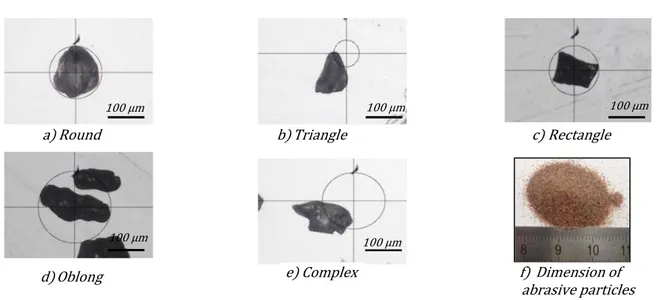
1.2.6.4 The effect of characteristics of abrasive particles ... 31
1.2.6.5 The effect of attack angle ... 33
1.2.7 Modeling of machining perpendicular to the workpiece surface ... 35
1.2.7.1 Abrasive water jet for milling a single kerf (elementary pass) ... 35
1.2.7.2 The effect of process parameters on the generation of a single kerf ... 40
1.2.7.3 Abrasive water jet for pocket milling ... 45
1.2.8 Modeling of machining with a water jet inclination angle ... 53
1.2.8.1 Considering the effect of jet attack angle on the generation of elementary pass ... 53
1.2.8.2 Pockets machining ... 56
Conclusion... 58
vi A new cutting depth model with rapid calibration in abrasive water jet
machining of titanium alloy ... 61
2.1.1 Introduction ... 62
2.1.1.1 Bibliography ... 62
2.1.1.2 Conclusion on the literature ... 66
2.1.2 Model of the depth milled in pocket machining ... 66
2.1.2.1 Modelling elementary passes ... 66
2.1.2.2 Principle for summing of elementary passes ... 68
2.1.2.3 Taking the erosion mechanism into account ... 69
2.1.2.4 Simplification of the cutting depth model ... 70
2.1.2.5 Formation of the pocket bottom in relation to the sweep pitch ... 71
2.1.2.6 Method to set up the machined depth model ... 73
2.1.3 Application of the method ... 74
2.1.3.1 The different configurations tested ... 74
2.1.3.2 The experimental set-up ... 74
2.1.3.3 Results obtained for configuration N° 1 ... 76
2.1.3.4 Identification of a rapid calibration procedure on configuration N° 1 . 78 2.1.3.5 Modelling with rapid calibration for configurations N° 2 to N° 6 ... 79
2.1.3.6 Experimental validation of the models established by rapid calibration . ... 83
2.1.4 Results and discussion ... 84
2.1.5 Conclusion ... 86
Adaptive speed control for waterjet milling in pocket corners ... 87
2.2.1 Literature review ... 88
vii
2.2.2.1 Depth model for milled pockets ... 90
2.2.2.2 Direction change strategies ... 93
2.2.2.3 Change of direction at constant radius ... 94
2.2.2.4 Conclusion on change of direction at constant radius ... 99
2.2.2.5 Adaptive speed control during change of direction at constant radius 99 2.2.3 Experimental validation ... 100
2.2.3.1 Experimental validation of adaptive speed control... 100
2.2.3.2 Results and discussion ... 102
2.2.4 Conclusion ... 104
... 106
A modeling of elementary passes taking into account the inclination angle 106 3.1.1 Introduction ... 108
3.1.2 Model of elementary pass taking into account the firing angle ... 110
3.1.3 The experimental set-up ... 111
3.1.4 Results and discussion ... 114
3.1.4.1 Experimentation ... 114
3.1.4.2 Rapid calibration method ... 116
3.1.4.3 Taking into account the erosion phenomenon ... 118
3.1.5 Conclusions ... 120
Machining pocket with management of the tool inclination angle ... 121
3.2.1 Introduction ... 122
3.2.2 Proposed model with the inclination angle of the jet ... 126
3.2.3 Experimental set up ... 128
viii
3.2.4.1 Assessment the proposed model for elementary pass ... 131
3.2.4.2 Assessment the proposed model for pocket ... 136
3.2.4.3 Influence of jet inclination angle on the geometrical characteristics of the milled pocket ... 139
3.2.5 Conclusion ... 146
... 148
General conclusions ... 148
ix
LIST OF FIGURES
Fig. 1-1. Problem with closed edges of pocket milled [40] ... 8
Fig. 1-2. Schema of the cutting head of PWJ [40] ... 10
Fig. 1-3. Schematic of high-pressure slurry jet (ASJ) [6] ... 11
Fig. 1-4. A typical system of abrasive water jet machining technology ... 12
Fig. 1-5. Components of abrasive water jet machine (FLOW MACH 4 – ICA Lab) ... 12
Fig. 1-6. Diagram of a booster pump(KTM water jet) [40] ... 13
Fig. 1-7. The velocity profile of the particles which constituting the jet [40] ... 14
Fig. 1-8. Schema of the cutting head of AWJ machine ... 15
Fig. 1-9. Water orifice [40] ... 16
Fig. 1-10. Abrasive orifice ... 17
Fig. 1-11. FLOW MACH4C ... 18
Fig. 1-12. Structure of a water jet at high velocity [48]... 19
Fig. 1-13. Flow of water jet according to N. Zuckerman et al [53] ... 19
Fig. 1-14. Impacting of a particle on the machined surface [54]. ... 21
Fig. 1-15. Erosion mode and two surface texture type in cutting ductile material [40] ... 24
Fig. 1-16. Machining parameters ... 26
Fig. 1-17. Effect of water pressure on depth of cut for different materials ... 27
Fig. 1-18. Effect of traverse speed on material removal rate and surface waviness ... 28
Fig. 1-19. Effect of standoff distance and traverse speed on dimensional characteristics of single kerf [57] ... 30
Fig. 1-20. Evolution of the depth (mm) according to the abrasive flow rate (g / min) [40] ... 30
Fig. 1-21. Different shapes of particles under an investigation using Tesa Visio apparatus ... 33
x
Fig. 1-22. Definition of attack angle of abrasive water jet ... 33
Fig. 1-23. Direction of the jet during machining ... 34
Fig. 1-24. A single kerf machined by abrasive water jet [51] ... 36
Fig. 1-25. Characteristic of a kerf profile ... 37
Fig. 1-26. An experimental validation using Gaussian to model a single kerf in milling Titanium alloy ... 37
Fig. 1-27. Comparison theoretical models with the measured profile of single kerf [51] 38 Fig. 1-28. Relationship between the GD width parameters and the simple Gauss model [40] ... 39
Fig. 1-29. Profile of single kerf extracted from "Alicona" optical profilometer [40] ... 40
Fig. 1-30. Effect of SOD and Vf on a single kerf [40] ... 42
Fig. 1-31. Effect of water pressure on a single kerf with SOD = 100 mm [40] ... 43
Fig. 1-32. Effect of the size of abrasive particle on a single kerf with SOD = 100 mm [40] ... 44
Fig. 1-33. Single kerf and pocket machined [40] ... 46
Fig. 1-34. Using mask for milling pocket [40] ... 46
Fig. 1-35. Zigzag strategy [106] ... 47
Fig. 1-36. Milling a rectangular pocket without mask [102] ... 48
Fig. 1-37. Deflects appear due to change the direction of the jet [45] ... 49
Fig. 1-38. Two methods of replacing by circular arc trajectories ... 50
Fig. 1-39. Constant radius of Ti6Al4V specimen machined [40] ... 50
Fig. 1-40. Modeling profile of pocket machined ... 51
Fig. 1-41. The evolution of the pocket depth as a function of traverse speed [40] ... 52
Fig. 1-42. The influence of impact angle on erosion damage for several stainless steels [110]... 54
xi Fig. 1-44. Schematic illustration of the jet plume structure in air before impingement onto
the target surface: (a) normal impingement and (b) shallow angle impingement [47]... 55
Fig. 1-45. Wavy surface profile measured for two levels of desired depth of pockets at α = 45𝑜 [111]. ... 56
Fig. 1-46. Milling experimental setup and cross-section of pocket milled [112]. ... 57
Fig. 1-47. Effect of the jet impact angle on characteristics of pocket milled [112]. ... 57
Fig. 2-1. Modeling of the Gaussian curve [44] ... 63
Fig. 2-2. Influence of operating parameters on elementary passes ... 64
Fig. 2-3. Offset passes and optimal abrasive flow rate ... 64
Fig. 2-4. Lateral offset and depths machined [45]... 65
Fig. 2-5. Profiles for elementary passes and abrasive size 220# ... 67
Fig. 2-6. Successive passes and pocket profile obtained by summing ... 68
Fig. 2-7. Direction of the jet after impact ... 70
Fig. 2-8. Influence of the sweep pitch on formation of the pocket bottom ... 72
Fig. 2-9. Method to set up the depth model ... 73
Fig. 2-10. Machine FLOW MACH4C ... 75
Fig. 2-11. Measurement device ... 76
Fig. 2-12. Mean profiles measured ... 76
Fig. 2-13. Measurement and modelling of elementary profiles ... 77
Fig. 2-14. Depths of pockets for configuration 1 ... 77
Fig. 2-15. Pocket with a corrugated bottom machined with P=100 MPa, SOD = 100 mm, abrasive size 220 #, Vf = 423 mm/min, B(423) = 1.420 mm and pitch = 1.71mm. ... 78
Fig. 2-16. Results obtained - Comparison of the depths calculated and measured ... 84
Fig. 2-17. Pocket with a slightly corrugated bottom machined with P = 225 MPa, SOD = 100 mm, abrasive size 220 #, Vf = 1.035mm/min, B(1035) = 0.993 mm and pitch = 1.02mm. ... 85
xii
Fig. 2-18. Changes in milling direction by 90𝑜 and corresponding defects [109] ... 89
Fig. 2-19. Changes of direction for triangular pockets [45] ... 89
Fig. 2-20. Distances on changes of direction ... 90
Fig. 2-21. Modelling the Gaussian profile ... 91
Fig. 2-22. Superposition of elementary passes ... 92
Fig. 2-23. Different changes of direction ... 93
Fig. 2-24. Changes of direction at constant radius ... 95
Fig. 2-25. Pitch and depth variations in constant radius strategy ... 98
Fig. 2-26. Relative depth variation for a constant radius strategy ... 99
Fig. 2-27. Correction of the pocket corner depth ... 100
Fig. 2-28. FLOW MACH4C machine ... 101
Fig. 2-29. Ti6Al4V milled ... 102
Fig. 2-30. Measuring a profile... 102
Fig. 2-31. Modeled and measured profiles ... 104
Fig. 3-1. Profile of elementary pass and pocket ... 109
Fig. 3-2. Influence of jet inclination angles on elementary pass profiles ... 110
Fig. 3-3. Profile corresponding to the jet inclination angle at 𝛼 ... 111
Fig. 3-4. Experimental setup specimens ... 112
Fig. 3-5. Measurement and extraction of elementary pass profile ... 113
Fig. 3-6. Modelled and measured profiles ... 114
Fig. 3-7. Width of cut for different inclination angles ... 116
Fig. 3-8. Depth of cut for different inclination angles ... 116
Fig. 3-9. Measured, calculated and corrected depth ... 117
xiii Fig. 3-11. Comparison of elementary pass profiles for SOD = 60 mm, Vf = 300 mm/min
... 119
Fig. 3-12. Direction of the jet during machining ... 125
Fig. 3-13. Schematic of elementary pass profile corresponding to the jet inclination angle at 𝛼 ... 128
Fig. 3-14. Experimental setup employed for AWJ machining of Ti6Al4V ... 129
Fig. 3-15. Measurement on Alicona ... 131
Fig. 3-16. The influence of the jet inclination angle on characteristics of the elementary pass. ... 132
Fig. 3-17. The influence of the jet inclination angle on characteristics of the elementary pass ... 133
Fig. 3-18. The evolution of depth and width of elementary passes at various jet impingement angles ... 134
Fig. 3-19. Dependence of material removal mechanism on the jet inclination angle... 135
Fig. 3-20. Influence of the jet inclination angle on characteristics of pockets milled (SOD = 20 (mm); P = 1000 (MPa); Vf = 1000 (mm/min), Pitch = 0.7 (mm) ... 137
Fig. 3-21. Influence of the jet inclination angle on characteristics of pockets milled (SOD = 20 (mm); P = 1000 (MPa); Vf = 1000 (mm/min), Pitch = 1.1 (mm) ... 138
Fig. 3-22. 𝐻𝑒(𝛼) factor defined experimentally as a function of jet inclination angle. The dot line represents the best fit line to the data based on Eq. 3-12: a) Pitch = 0.7 (mm); b) Pitch = 1.1 (mm) ... 139
Fig. 3-23. Explanation of different erosion rate from inclination angle of the jet ... 140
Fig. 3-24. Variation in the depth of pocket with two cases of the pitch ... 142
Fig. 3-25. Definition of the width of milled pocket ... 143
Fig. 3-26. Variation in the width of pocket with two pitch cases ... 144
Fig. 3-27. Definition of the slope of pocket wall ... 145
xiv Fig. 3-29. Slope of pocket wall increased as repeating the trajectory over the same pocket milled at 50𝑜 ... 146
xv
LIST OF TABLES
Table 1-1. Applications of AWJ machining in different industries. ... 3
Table 1-2. Applications of AWJ machining in composite materials. ... 6
Table 1-3. Summary table of the influence of process parameters [40] ... 45
Table 2-1. Configurations tested. ... 74
Table 2-2. Rapid calibration on configuration 1. ... 78
Table 2-3. Rapid calibration for configurations 2 to 6. ... 80
Table 2-4. Errors for the various configurations tested. ... 85
Table 2-5. Distance in three areas. ... 97
Table 2-6. Distance in three areas considering 𝑃𝑖𝑡𝑐ℎ𝑖𝑛𝑡 ≪ 𝑅. ... 97
Table 2-7. Relative depth variation in the three areas. ... 98
Table 3-1. Constant operating parameters. ... 113
Table 3-2. Ke(𝛼) coefficient. ... 118
Table 3-3. A given machine configuration. ... 130
Table 3-4. Modeled and measured depth for milling pocket at different inclination angles. ... 143
xvi
GENERAL INTRODUCTION
The development of the material science has introduced a wide range kind of materials with especially properties such as harder (ceramics); heterogeneous structures (composites); heat sensitive (shape memory alloys); being higher strength at elevated temperatures (aerospace alloys). Machining such materials is not easy by conventional methods. It leads to a requirement of replacing familiar methods by new technologies from production researchers to solve such engineering difficulties.
In a particular domain, the aerospace industry, a necessity is to cut down component weight from galling materials such as Ti6Al4V. There exist some available processes to satisfy such material manufacturing, which are chemical milling and abrasive water jet machining. These two methods, with a vital advantage of imposing negligible forces, allow processing flexible structures of aerospace parts. Nevertheless, with the disposal of wasting acids into the environment, the chemical milling process is being surfed under threat because of the high costs of the required jobs for the acid treatment after machining. Meanwhile the abrasive water jet machining is considered promising as a versatile machining processes which can become a replacement for conventional methods for Ti6Al4V. Although abrasive water jet has received significant attention from researchers currently, most study results are applied for cutting. A few applications of abrasive water jet processes for controlled depth milling of Ti6Al4V are found in the literature, thus this field is still at new stage.
Some reports indicated a possibility of abrasive water jet (AWJ) technology to perform controlled depth milling of Ti6Al4V and can potentially apply to the aerospace industry. This domain regards to the characteristics of surface roughness, grit embedment and surface morphology as important parameters to evaluate the fatigue life of components machined by AWJ machining. However, the milling performance for a controlled depth requires a series experiment need to be conducted due to very complex process parameters while lacking a fully understand the machining process and cutting mechanism.
Therefore, in the initial stage, controlled depth milling and process modeling are being a fresh functionality to dig into due to the effects of process parameters is not clearly
xvii understood. So, at the moment it is hard to obtain an expected milled depth on machining Ti6Al4V.
From the above reality, the contents of this Ph.D. work present a comprehensive study to develop a novel experimental methodology applying to abrasive water jet technology for hard metal milling applications, Ti6Al4V.
Managing the machining process parameters and manipulating the attack angle of the jet on the surface of a workpiece aims to jet does not cut through the workpiece while removing material. This methodology is able to machine at constant or variable depths by establishing machining configurations in which some process parameters are fixed by the machine technology. This thesis is composed of four chapters the first being introduction and the rest two dedicated to two cases corresponding to a perpendicular angle and an inclined angles of the jet.
Chapter 1 presents context of abrasive water jet technology and an historical brief of evolution of this technology. Along with a detailed study of the technology of abrasive water jet machines and its abilities to machine all materials, the effect of process parameters will be presented. This introduction part shows a very suitable process for machining of hard metals parts with thin thickness.
Chapter 2 is dedicated to the first case of abrasive water jet machining with a perpendicular attack angle of the jet to the workpiece surface. An experimental investigation is first undertaken to study the major milling performance in AWJ single pass milling on Ti6Al4V. Experimental analysis has been conducted to define a model in order to describe the single kerfs milled according to controllable parameters. Then this chapter exhibits a new model to compute the depth when milling pockets in aspect of open edges. Based on a given configuration including a given machine, specific pressure with a constant value of the firing distance of the jet, a new rapid calibration is introduced. It allows a saving of setup time to establish a model to predict the depth of cut on machining open pockets. Then, a proposed methodology is applied in milling the corner of pockets with an imposed corner radius. This new methodology permits to solve problems usually suffer in the course of machining pocket corners, especially the
non-xviii uniform in depth. This method of generating the best strategy with a suitable traverse speed of the jet will be able to obtain a flat bottom on whole a pocket machined.
Chapter 3 presents the management of the jet firing angle that is a kinematic parameter. A new model of kerf profile taking into account the firing angle of the jet is introduced. The proposed model can be developed for the simulation of AWJM process and pave a way for milling flat bottom pockets and 3D complex shapes. To do that, further experiments are implemented to validate the effects of tool inclination angles on the formation of pockets milled in abrasive water jet machining.
Finally the general conclusion will summarize the main contributions of this study and will detail the possible developments to contribute to the implementation of industrial applications of 5-axis machining of free form parts with abrasive water jet milling.
1
State of the art
Context
1.1.1 Evolution history and characteristics
of abrasive water jet technology
The crucial point of the abrasive water jet machining technology is to make use a water at ultra-high pressure to mix abrasive particles, air, and water together to become the jet. A combination between input process parameters with suitable tool paths of machining strategies of the jet is considerable versatile and potential to cut any kind of material from soft materials (wood) to hard materials (metal alloys) along with the economic profit of saving material and time.
Historically, in the late years of 1950s decades, in the attempts of seeking a new solution to cut the wood, Norman Franz [1] discovered the fundamentals of the high– pressure water jet cutting by dropping heavy weights onto columns of water to force the fluid through a very fine orifice. The pressure powerful of water was enough to cut the wood and other materials. Some years later, in the 1970s, M. Hashish [2] was successful in conducting the first application of adding the garnet into the high-pressure water to extend the capability of the jet to cut any kinds of materials. Then, the water jet cutting process has been industrialized and commercialized in the market with a wide range of applications.
Following this way, researchers have focused on this field in order to investigate the process and improve its abilities. In his study [2], M. Hashish introduced the state of the art of the abrasive water jet cutting technology at very high pressure along with preliminary milling experiments on different materials such as aluminium, titanium, glass and graphite composites. Results confirmed that this non-conventional method is very versatile for cutting and it is one of the most energy methods and that has an outstanding potential to apply in milling application. Besides, other studies have shown the properties
2 and structure of the abrasive water jet, also the influence of parameters of the cutting process, and the modelling of cutting performance in brittle and ductile materials[3], [4].
The cutting technology with high water pressure is cataloged in three types: (i) pure water jet (PWJ), (ii) Abrasive water jet (AWJ) [5], (iii) abrasive slurry jet (ASJ) [6].
1.1.2 Ecological machining with only sand and water
When compared with other traditional and non-traditional machining processes, abrasive water jet technology shows it’s environmentally friendly and ecological machining method. Materials supplying for process the operation in this technology are only water and abrasive particles.
Water can be collected directly from the wild through normal water supply systems. Before entering the machine, it is passed through some water purifiers to remove impurities or residues that can cause damages on high pressure pump.
Besides, using abrasive particles are also eco-friendly and it does not require a complex process to produce them. Abrasive particles are mostly from two resources: abrasive from natural origin and abrasive from a manufacturing operation (synthetic materials). The former that is available in large quantities in mines or sand-works and easily is gathered by crushing and sieving. The latter involves abrasive particles manufactured industrially.
1.1.3 Flexible manufacturing processes with different materials
Abrasive water jet cutting is an application broadly used in various industries:
manufacturing industry, construction industry, coal mining industry, food production industry, electronic industry, and cleaning industry.
AWJ machining has been used to cut difficult-to-cut materials including ductile materials [7]–[10] and brittle materials [11]–[14]. These kinds of material could be machined by either conventional method (diamond saws) or other non-conventional methods such as plasma, lasers. However, heat – affected zone generated may produce undesirable changes in material characteristics and cannot meet the requirement of some features respected. Some specific applications [15] are presented (Table 1-1):
3
Table 1-1. Applications of AWJ machining in different industries.
Domain Description of application
Aeronautics Cutting process for materials such as titanium bodies for military aircrafts, engine components, aluminum body parts and interior cabin parts Automotive Parts such as interior trim (headliners, trunk liners, door panels), fiberglass
components, and bumpers
Construction Cutting and scarifying for reinforced concretes, sandblasting and cutting corroded rebar, drilling holes for bolting posts, repairing road and bridge, underground work and pile cutting
Oil and gas Casing cutting for decommissioning of oil wells, rescue operations, platform cutting and repair, and pipe cutting
Coal mining Being able to safely cut metal structures in the potentially explosive environment underground, digging coal with high productivity
Electronic industry Cut out smaller circuit boards from a large piece of stock without damaging them and a very small kerf width. So there is no much waste of materials
Food industry Food preparation, cutting some certain foods such as bread and the fat from meats
S. Paul et al. [16] presented the material removal mechanism of ductile materials with erosion models. The concept of generalized kerf shape is introduced into a qualitative model and the analytical model to predict the total depth since cutting aluminum and steel. Besides, cutting process for a total of six different metals i.e. Al 7075-T6, AISI 4340, molybdenum, Monel 400, ANSI 304 and Ti6Al4V is conducted by D. Arola et M. Ramulu [9]. They noted that the extent of deformation was found to depend on the strain hardening behavior of metals and the abrasive attack angle. A model for the depth of deformation and the depth of plastic deformation was found to be inversely proportional to the strength coefficient of metals. J. J. Rozario [17] proposed empirical models were built based on the experimental data in terms of different parameters i.e. depth of cut, kerf width and surface roughness and then using Taguchi’s design of experiments and analysis of variance (ANOVA) to analyze the performance of AWJs in cutting 6063-T6 aluminum alloy.
G. Fowler et al. [18] have used a milling process on titanium alloy to observe grit embedment and surface morphology which is considered as important factors that affect to the service life of components manufactured. He has noted that with a high traverse speed and at low impingement angles or with low speed milling at jet impingement angles
4 up to 45𝑜 in the backward direction only, the grit embedment can be minimized. M. Hashish [7] demonstrate the feasibility of using AWJ process for controlled depth milling of gamma Titanium aluminide. It has been indicated that it’s possible to mil thin skins of about 0.5 mm with an accuracy of 0.025 mm with a jet angle of 15𝑜 firing angle. According to a study of M.C. Kong [10] applied AWJ to mill a function shape memory alloys (NiTi SMAs) considering water jet temperatures with and without abrasives particles. Results show that abrasive water jet is more efficient than plain water jet to control the milled depth.
B.H. Yan et al. [19], [20] applied AWJ technology for polishing SKD61mold steel. SiC abrasive particles of various diameters were used with compound additives of pure water, water-solvent machining oil and water wax. The results showed that wax-coater particles not only produce a higher quality surface finish, but also save the polishing time. Application of AWJ is found further in turning process as presented by R. Manu et al.[21]. The experiment was conducted on 6063-T6 aluminum alloy cylindrical specimens in order to model the AWJ turning process considering material removal from the circumference of a rotating cylindrical specimen. The I. Finnie’s model was used to evaluate the volume of material removed by impacting of particles taking into account the attack of the jet.
Regard to application of AWJ in brittle material. S. Paul et al [22] conducted cutting process on Polycrystalline ceramics and proposed the material removal mechanism with an analytical model developed to predict the total depth of cut. The model has been built using the hypothesis of the material removal mechanism that takes place in two zones on the machined surface i.e. micro-cutting and fracture in the first zone and plastic deformation and fracture in the second zones. This model also takes into account the size and shape of the abrasive particles. Experiments in AWJ cutting for Alumina ceramics is carried out by J. Wang [23] to study the effects of nozzle oscillation on the depth of cut with different combinations of process parameters. He showed that with nozzle oscillation at small angles and the cutting parameters being correctly selected the depth of cut can increase up to 82%.
A. Ghobeity et al. [24] implemented the drilling process for holes on glass and polymers with models to predict AJM erosion profiles when drilling holes with and
5 without masks. Besides, application of this technology for the grinding process is also found in studies of Z. W. Zhong et al [25] for glass and M.C. Kong [26] for Al2O3.
1.1.4 An appropriate
process for machining of hard metals thin sheets
Aviation industry uses hard-to-machined materials. Furthermore, aviation parts are mostly thin parts with large size in dimensions. Manufacturing these parts requires to remove material selectively from their surfaces. Several processes are possible but they all present drawbacks:
Conventional milling. Inherent problems are galling tendency, tool wear and deformation due to significant cutting forces and temperature gradient applied to the workpiece.
Electro discharge machining. Material melting and re-solidification process cause in decreasing fatigue life of engineering components due to recast layer phenomenon [27].
Laser machining. The high temperature during process leads to component distortion and fatigue life is reduced significantly [27].
Chemical machining: in order to respect environmental safety, acids used must be treated before disposal. A significant cost is associated to this treatment. Furthermore, in order to remove material on selected areas, masks have to be prepared. Then these masks are installed before machining and must be removed afterwards.
Abrasive water jet machining: the main disadvantage of this process is a low material removal rate (MRR) due to the use of improper cutting machines. In order to improve the MRR, it is first necessary to identify the elimination mechanisms corresponding to the considered material. Then, appropriate machining heads must be developed.
1.1.5 Parallel development in CFRP application
6 Carbon Fiber Reinforced Plastic (CFRP) is getting apply widely (Table 1-2) in aerospace, marine, construction, military applications. These kind of composite materials show several outstanding advantages in characteristics: a very high strength-to- weight ratio / high modulus-to-weight ratio and corrosion resistance. To employ these composites, some machining operations such as milling, cutting, polishing, grinding, and drilling are usually required to meet demand of the final functional component [28]. Besides, machining processes are also necessary to repair composite components at where appear damaged.
However machining of the composite materials is truly hard to do because of inherent properties such as the anisotropic and non-homogeneous structure of composites, a high abrasiveness and a huge variation in their mechanical, thermal and physical properties. [28], [29]. On milling process operation of CFRPs, studies have reported the appearing of some types of deteriorations i.e. delamination, fiber pull-outs, matrix recession, inter-laminar cracks and thermal degradation, which will destroy mentioned outstanding characteristics of composite materials [30], [31].
From these limitations of the conventional methods on machining CFRPs, it has prompted scientists to find alternative non-conventional methods. Abrasive water jet process demonstrates good abilities to machine any kind of materials and also composites. [32], [33]. During the process operation, the jet creates minimal forces attacking to the target surface without heat treatment. Besides, this technology does not require any specific tooling or equipment.
1.1.5.2 Application of abrasive water jet technology for machining CFRP
The Table 1-2 shows different applications of AWJ for machining CFRP which are listed in the literature.
Table 1-2. Applications of AWJ machining in composite materials.
Material Application Description Reference
Advanced engineering composite materials -AECMs (carbon fiber, glass fiber and
Milling It is possible to mill a wide range of advanced engineering composite materials at high productive mask-less. Results show that fiber damage can be reduced by suitably controlling the energy of the jet with reasonable water jet process parameters and jet path
D.S. Srinivasu, D.A. Axinte – 2014 [34]
7
carbon-glass fiber).
strategy. The surface integrity milled can be improved by minimizing the damage and can effectively controlled by keep a uniform exposure time of the jet.
Unidirectional graphite/epoxy composite material
Cutting A comparison surround the surface characteristics after cutting by abrasive water jet and water jet is conducted on graphite/epoxy composite. It is drawn that abrasive water jet machining is more feasible machining process fort these kind of materials owing to material removal mechanisms and surperior quality surface generation.
M. Ramulu and D. Arola - 1992 [35]
Graphite/epoxy composites
Cutting An investigation of the mechanism of delamination under AWJ machining on graphite/epoxy composites. It shows that at the initial cutting phase, the shock wave of the jet results in crack tips and then water penetration into crack tips is the main causes of delamination. A semi-analytical model to estimate the maximum delamination length is proposed. J. Wang et al. – 2008 [36] FRP & CFRP material
Cutting The effect of process parameters on generation of kerf taper angle is observed on two types of composite materials graphite/epoxy and glass epoxy. Based on the energy conservation approach…. D.K. Shanmugama et al. – 2008 [37] Carbon fibers reinforced plastic (CFRP)
Milling Using AWJ for milling carbon fiber reinforced plastic (CFRP) composites, the influence of process parameters on material removal rate, surface quality and nature and size of defects are studied. Along with Ra, a newly criterion
crater volume ‘Cv’ was proposed to evaluate the machined surface quality based on the quantification of the crater defects.
A. Hejjaji et al.
[29], [38]
CFRP/ Drilling CFRP/Ti6Al4V stacks were machined
with abrasive water jet using different process parameters in order to evaluate the ability of AJW application for the drilling process. A positive taper angle is observed in Ti6Al4V while a negative is observed in CFRP in almost all cutting conditions. depending on the stack configuration, X-type or barrel-type kerf profile will be obtained
A. Alberdi et al. - [39]
8
1.1.6 Drawbacks of Abrasive water jet machining
Even if the abrasive water jet technology is a very useful machining process, especially in cutting processes, there exist some restrictions on this technology:
- A complex process with various input parameters makes many challenges to manage whole the process. The quality of machined products depends obviously on the characteristics of the jet, and on the induced workpiece erosion mode (cutting or deformation wear). Besides, to obtain a specified value of the cut depth, the accuracy is affected by a real time of performance (exposure time). This exposure time is the interaction real time between the jet and workpiece, and it becomes more complicated to manage it when the jet direction is changing following machining trajectories (Fig. 1-1).
Fig. 1-1. Problem with closed edges of pocket milled [40]
- If the workpiece thickness is too high, the jet cannot cut through. It results in waviness pattern that occurs at the lower part of the cut surface due to jet deflection (Fig. 1-15).
- Abrasive particles lose energy when cutting along the thickness. It results in a kerf taper that has to be managed if particular wall geometry is required. (Fig. 1-46).
- Wear is due to the abrasive affecting the mixing chamber and the focusing tube. Or wear due to high water pressure affects the nozzle. The geometry of the jet is influenced by these wear and the quality of the machined surface is directly impacted
Zone of deeper spots on both edges of the pocket milled
Stopping point
Points where the direction changes
9 - During abrasive water jet milling, the jet does not pass through the workpiece and bounces off the surface. A cloud consisting of vapor and abrasive particles in suspension is thus produced. For industrialization of this process, hygiene and safety devices must be adopted.
- It has been noticed that there are generally problems associated with the use of this technique including the grit embedment on the machined surface, insufficient tolerance on the depth of cut; unsatisfying surface waviness and surface roughness of the milled areas[8].
Review of abrasive water jet process
1.2.1 Technology of abrasive water jet machines
Industrial applications of abrasive water jet technology are getting more popular than ever. The jet can be considered as a non-conventional machining tool to machine difficult-to-cut materials productively. These materials include hard metals, ceramics, marbles, and composites without creating the heat and affected zones during machining. In addition, the effects of cutting force on the workpiece are also neglect. As such outstanding advantages, abrasive water jet machining has been utilized to machine ductile and brittle materials.
1.2.1.1 Pure water jet technology
Pure abrasive water jet (Fig. 1-2) is identified by using a pure water to make a cutting operation. This type of cutting is limited to soft materials such as fabrics, PVC, plastics, ceramic fabrics, fiberglass, rubber, food and leather. This process is very fast and extremely efficient with low cutting force. A pure water is directed into a collimation tube through which the water is intensified to a high pressure. Then a nozzle with a small orifice made from sapphire, ruby or diamond is used to accelerate the water particles. Due to a friendly with the environment and healthy, the pure water jet has a lot applications in the food industry as well as in the medical field [5], [41]. For this application, the water pressure was varied between 20 and 120 MPa.
10
Fig. 1-2. Schema of the cutting head of PWJ [40]
1.2.1.2 Abrasive slurry jet technology
Abrasive Slurry Jet system (ASJ) is a water jet charged with abrasive. The abrasive and water are mixed already in a separate container and this mixture is pumped through the small orifice (Fig. 1-3). During performance, there is no entrained air to ensure that the characteristic of jet is homogeneous without a water droplet zone at small standoff distances.
At low pressure, the penetration rate of the jet on the target surface is not significant because of low kinetic energy of the jet. In this way, ASJ is seem to be feasible process to be benefit not only for cutting, but also for milling of multi-material [11], [42]. However, with high-pressure slurry, some problems related to the wear of the orifice and the focusing tube appears [43].
Nowadays, Abrasive slurry jets has been mainly developed for micro-machining because of some advantages over traditional micro-fabrication technologies. It is a very promising application in milling of micro-channels, especially in micro-fluidic devices and micro-electro-mechanical systems [6].
SOD
Collimation tube High pressure water
Water orifice
Pure water jet Cutting kerf Workpiece
11
Fig. 1-3. Schematic of high-pressure slurry jet (ASJ) [6]
1.2.1.3 Abrasive water jet technology
The main idea of the abrasive water jet technology is to make use a water at ultra-high pressure to mix abrasive particles, air, and water together to become the unique jet. Using the intensifier technique, water is pumped to a very high pressure. Following through a small orifice of sapphire or diamond materials, high pressure water is converted to a very high velocity jet of water. Then, when it comes out of the orifice and go into a mixing chamber, abrasive particle (garnet, silicon carbide, alumina etc.) are added to the jet. The energy of the water will be gradually transferred to the particles within the mixing chamber as well as in the focusing tube. As a results, an abrasive water jet with high speed is generated. This jet will erode the target materials when it impacts.
Abrasive water jet technology is an advanced machining tool used to machine typically difficult to cut materials. In a typical system of abrasive water jet machine (Fig. 1-4), a hydraulically controlled high-pressure pump delivers the water to an accumulator that produces a uniform flow of high-pressure water and then high-pressure water moves to the cutting head.
Inlet slurry High-pressure water Water orifice Mixing chamber Focusing tube Jet of abrasive, water without air
Slurry tube
Workpiece
12
Fig. 1-4. A typical system of abrasive water jet machining technology
1.2.2 Working system of abrasive water jet machine
Fig. 1-5 is a typical illustration of a technology system of abrasive water jet machine. The system is comprised of three main groups: the ultrahigh-pressure pump, the machine, and the control system. In what follows, the attention will be concentrated in some main components in these groups.
Fig. 1-5. Components of abrasive water jet machine (FLOW MACH 4 – ICA Lab)
The ultrahigh-pressure system: The pump, cutting head and plumbing
The control system:
The programming software, operator interface, drive motors, and position and velocity feedback system
The machine:
The X, Y, Z axes, cutting head wrist axes, and material support catcher
13
1.2.2.1 The ultrahigh-pressure pump
Water is pressurized by a high-pressure pump and can reach about 400 MPa for piston pumps and 600 MPa in booster pumps (Fig. 1-6). Then, this piston allows the compression of water in rooms that play the role of water accumulator equipment.
A booster pump generates a very high pressure of water owing to a transmission pressure from a hydraulic (oil) circuit to a water circuit [40]. However, this kind of pumps operates at a low frequency of the order of 40 cycles per minute. For cutting, the low frequency of high-pressure pumps does not affect the cutting process. However, for water jet milling, any variation in pressure, or flow is not accepted to avoid a variation in the machined depth. For this reason, piston pumps are usually employed in AWJ machines.
As a pressurized water is passed through an orifice, a high-speed water jet is generated. The profile of abrasive water jet at the exit of the focusing tube is shown in Fig. 1-7 and it is described as a function of the distance travelled.
Fig. 1-6. Diagram of a booster pump(KTM water jet) [40]
In the study of A.W. Momber et al.[3], they has mentioned about using Bernoulli’s Law and nozzle coefficient to define the velocity of the water jet (Eq. 1-1).
Sealing plug High pressure cylinder Piston extension Cylinder head Seal cartridge Packing nut Sealing head
Cylinder shirt High pressure sealing
Cylinder hydraulic
14 𝑣𝑤𝑎𝑡𝑒𝑟 = 𝜂√
2 ∗ 𝑃𝑤𝑎𝑡𝑒𝑟
𝜌𝑤𝑎𝑡𝑒𝑟 Eq. 1-1
In this expression, 𝑣water is the speed of water, 𝑃water is the hydraulic pressure, 𝜌water
is the density of the water. The coefficient 𝜂 denotes the nozzle efficiency that is defined by characterizing momentum losses because of wall friction, fluid-flow disturbances and compressibility of the water.
There are three phases of the velocity profile of the jet [40]:
A consistent jet zone where the velocity where the velocity profile of the particles is almost uniform. This zone is usually used for cutting with a low standoff distances.
A central zone (Zone A) where focused energy of the jet and the speeds is highest with small quantities of abrasive particles in this zone.
A lateral zone (Zone B) contains a large number of abrasive particles and lower speeds.
Fig. 1-7. The velocity profile of the particles which constituting the jet [40]
In literature [44]–[47], the velocity profiles were considered as the form of a bell. This bell profile will be widens and flattens as it moves away from tip of the focusing tube.
Focusing tube
SOD
Evolution of the particles
velocity profile and Jet’s Gaussian profile
Consistent zone
Central zone and concentrated energy where the energy is high
(Zone A) Lateral zone of the jet Where the energy is low
(Zone B)
15
1.2.2.2 Abrasive feed system
The abrasive feed system consists of an abrasive hopper, an abrasive controllable valve, and a delivery pipes. The abrasive hopper plays as a container to store the abrasives. The abrasive controllable valve turns on/off the abrasive flow.
1.2.2.3 Water and air
The water used in this technology is pre-filtered network water (particles larger than 10 μm) before entering into the pump. It is then filtered twice at the inlet of the pump by two filters, one of 1 μm and the other of 0.5 μm. This filtering system eliminates macros and micro-molecules that can block pumping and damage the pump[40].
Air which is drawn into the jet along with the abrasive particles and it takes more than 90% of the total volume of the tri-phase jet [40]. The air does not contribute to the removal material.
1.2.2.4 Cutting head
Fig. 1-8 show a cutting head of the abrasive water jet machine with its cross-section. The design of the cutting head allows the entrance of abrasive particles, then effectively mixing of abrasive particles and water in a mixing chamber.
Fig. 1-8. Schema of the cutting head of AWJ machine
Hopper
Abrasive orifice
Abrasive particles
Abrasive water jet High pressure water
Water orifice Mixing chamber
Focusing tube
16 On working, the abrasive particles in the abrasive distributor located above the cutting head go into the mixing chamber due to itself gravity and the Venturi effect by the passage of the jet of water in the cutting head. At the end of working, as soon as stop supplying the abrasive, the inlet pipe is rapidly cleaned by the jet which contains only pure water at that moment.
Besides, thanks to a sapphire or diamond water orifice with a very small diameter from 0.1 to 0.4 mm, the energy of pressurized water is converted into kinematic energy which will be gradually transferred to the abrasive particles. Consequently, the stream of water, abrasive particles, and air are accelerated and directed to go to the focusing tube that allows concentrating the jet (Fig. 1-8). When the jet attacks a target surface, it will remove the material of the surface and form incisions. The geometry of the incision depends on, the one hand, properties of machined materials (ductile, brittle, or composite material) and, on the other, the combination of a set of process parameter in the operation.
1.2.2.5 Water orifice
Water orifice plays the role of a transformation of the pressure exerted on water particles to speed. It is made of a diamond, ruby or sapphire those materials of high wear resistant (Fig. 1-9). This structure facilitates the shape and consistency of the jet.
Fig. 1-9. Water orifice [40]
Pressurized water
Ruby, sapphire or diamond Stainless steel body
17
1.2.2.6 Abrasive orifice
Abrasive orifice (Fig. 1-10) defines the abrasive flow rate, abrasive particles pass through the abrasive orifice then go to the abrasive pipe and finally enter into the mixing chamber. For different types of abrasive particle, the variation of the abrasive flow is a function of the orifice diameter.
Fig. 1-10. Abrasive orifice
1.2.2.7 Mixing chamber and focusing tube
The focusing tube (Fig. 1-8) directs the jet to the cutting target and normally for AWJ cutting process, the focusing tube have a short entrance cone to facilitate abrasive grit entry. The length of the focusing tube affects particle velocity due to the frictional losses. Hence, an optimal structural design of tapered inlet, focusing tube diameter, and the length will limit erosion of the focusing tube [4].
1.2.2.8 Abrasive particles
Abrasives are mostly cataloged in two main families: abrasive from natural origin and abrasive coming from a manufacturing operation (synthetic materials). The former, a case of garnet, which is available in large quantities in mines or sand-works and easily
Abrasive distributor
Abrasive pipe line Abrasive orifice
Cutting head
18 is gathered by crushing and sieving. The later involves abrasive particles manufactured industrially to meet specific demands.
1.2.2.9 The position control system
The position control system directs the cutting head follow to the programmed path. It consists in a 3axis or 5axis CNC machine.
For this study, it should be noted that all experiment is conducted on a FLOW MACH4C (Fig. 1-11) equipped with a PASER4 cutting head. The nozzle was of diameter 0.33 mm and the focus mechanism 1.02 mm in diameter and 101.6 mm in length. The pressure was generated using a Hyplex-Prime pump with a maximum of 400 MPa. Control of the NC machine was ensured by two software packages (Flowpath and Flowcut) provided by FLOW.
Fig. 1-11. FLOW MACH4C
1.2.3 Characteristic of the jet
K. Yanaida et al.[48] investigated a vast of experiments on geometrical structure of the jet (Fig. 1-12). The jet is divided into three zones along the axial direction consisting of the initial zone, the main zone and the final zone. They confirmed that the flow
Abrasive orifice
Water orifice 0.33 (mm)
Water orifice
Focusing tube
19 properties are constant along the jet axis and the length of these zone depends on the diameter of the orifice, water pressure and jet velocity. M. Hashish et al. [49] investigated the high velocity cutting performance of the jet and showed a similar conclusion. Inthe transition zone (Fig. 1-12), the water velocity is a function of the jet radius and the radial profile of the water velocity has a typical bell shape.
Fig. 1-12. Structure of a water jet at high velocity [48]
Several studies [5], [46], [50]–[52] showed that on working, particles flowing along the jet come and contact with material to be machined with a Gaussian distribution of particles (Fig. 1-7). Inside of the jet, there exists an inner zone A and an outer zone B (Fig. 1-7). Due to the friction interacting with the inner surface of the focusing tube, the velocity of particles in outer zone B is smaller than that in inner zone A. During machining, Impact mechanism plays the main role in removing material along the jet axis (Zone A) (Fig. 1-13).
Fig. 1-13. Flow of water jet according to N. Zuckerman et al [53]
Initial region Main region
Do
Final region Continuous flow region Droplet flow region Diffused flow region Potential
core
Transitional region
Velocity core region
Boundary of a droplet layer
Boundary of a final droplet layer Nozzle
Zone B where particles sliding on the surface
causing the abrasion phenomenon. Zone A where particles
attack on the surface causing the impact
phenomenon.
Workpiece Initial region
Jet stagnation region
Core region
20 In addition, an erosion mechanism takes place, with particles on lateral zone of the jet (zone B). In other words, when machining, the action of the abrasive particles during process includes impact phenomenon and abrasion phenomenon (Fig. 1-13).
1.2.4 Material removal mechanism (Micro – Macro machining)
1.2.4.1 Removal material mechanisms in AWJ machining
In AWJ machining materials are divided into two main groups: ductile and brittle materials [42]. Removal mechanism of ductile materials is generated by a plastic deformation in which material is removed by the displacing or the cutting action. For a brittle material, the impact of the abrasive particles results in material removal owing to expand from initial cracks created out from the point of impact of the abrasive particles on the target [54].
In what follows, we will consider these two kinds of the material removal mechanism.
1.2.4.1.1 Erosion mechanism in ductile materials
The erosion mechanism of ductile materials in AWJ process is micro cutting. This action of material removal is considered similar to that of abrasive grains when grinding. Most of the material erosion models reported based on well-known models of I. Finnie [54], J. G. A. Bitter [55], [56], and M. Hashish [57].
The early model of erosion mechanism for the ductile material was introduced by I. Finnie [54]. The eroded volume is the consequence of the trajectory of the particle which interacting with the surface (Fig. 1-14). The interaction between the cutting face of the particle and the machined surface depends on the characteristic of particle, i.e. geometry, shape, hardness. Several hypotheses had been formulated to simplify the problem i.e. (i) there is only one cutting action producing material removal mechanism and this cutting action is harshly controlled by plastic deformation; (ii) there is no crack propagation of the particle during the impact ; (iii) the particle does not break up for impacting and move in a plane movement. Applying these hypotheses, I. Finnie has proposed two efficient expressions to predict the volume of material removed by abrasive water jet micro-machining.
21
Fig. 1-14. Impacting of a particle on the machined surface [54].
However, the prediction models for material removal volume is just suitable for low impact angles and the impact angles around 90𝑜 were not considered. Besides, the
phenomena of impact that may cause in a fragmentation of impacted surfaces was not taking into account. The models of I. Finnie had been improved in later studies.
Latterly, J. G. A. Bitter [55], [56] had evolved I. Finnie’s model by taking into account another erosion behavior that is erosion due to deformation. As a collision of a particle on a target leading to erosion of material, there are two erosion mechanisms of the removed material. It is due to two different components of velocity vector. The tangential component of the velocity vector of a particle (Vpcos) that causes in cutting or shearing
erosion. The other is the normal component of the velocity vector (Vpsin) in which
material is removed by plastic deformation. The particle has been assumed that it is equivalent to a sphere and it only undergoes an elastic deformation. As soon as attacking a target material, if the maximum impact stress does not exceed the material elastic limit, the impact is elastic. Otherwise, that is the plastic deformation of the collided surfaces which results from the repetition of impacting. He developed two equation to calculate the material removal under each mechanism. Thus the model of J. G. A. Bitter is more comprehensive because there was a wide range of impact angles studied. For a given situation and to adapt his model, it is necessary to identify several parameters experimentally.
On impacting, if the vertical component of the particle velocity overtakes the limit speed, Ve, the material deformation is plastic and the horizontal component of velocity
∅ 𝛼 l 𝑦𝑡 𝑥𝑡 x y
22 produces a shear stress on a correspondent surface at the vertical section. In case of the stress in this section is greater than the shear stress of the material, the material will be removed. The action of the particle can then be separated into two stages. The first one is plastic deformation and the material is removed mainly due to this effect. This stage ends when the vertical component of the particle get to zero value. As a result of the repetition of the forces of the particle (rebounding), the particle goes out of the material.
Recently, M. Hashish’s model [57] was performed in the case of cutting. Based on the I. Finnie’s model, the cutting heights are defined by the impact of an abrasive water jet on a ductile metal material. The computation of the cutting depth considers, the physical and geometrical characteristics of the abrasive particle. M. Hashish presented the cutting process includes two modes, i.e. the cutting erosion mode and the deformation erosion mode. In the first mode, the material is removed by particle impact at angles, and in the second mode, the material is removed due to excessive plastic deformation by impacts at large angles. In his studies, M. Hashish presented three cases of the particle impact corresponding to three expressions of the removal material volume.
The two material removal mechanisms are the critical fundamental of the phenomenology of abrasive water jet. They are obtained by purely experimental analysis methodology during the process with different material removal mechanisms considered and characteristic of abrasive particles (geometry, velocity, and trajectory).
1.2.4.1.2 Material removal mechanism in brittle materials
The erosion of brittle material is a complex process [16], [24], [58], [59]. Although most studies are applied to specific cases of brittle materials, researchers agree that the brittle fracture behavior (cracking process) plays the main role in removing this type of material.
In his study, I. Finnie [54] stated that a simple approach is no longer accomplishable for brittle material. At the moment of the initial fracture being appeared, the rate of material removal depends on the inner propagation tendency, of the fracture and association with other fractures.
23 J. G. A. Bitter [55], [56] also introduced an expression to compute the material volume eroded by brittle fracture. D.B. Marshall et al [60] have investigated the formation of lateral crack in numerous brittle materials. Based on Vickers indentation, they proposed a lateral crack function of the subsurface on target material, which describes the relationship between the machined material and the indentation force to predict the length and depth of the cracks.
Slikkerveer et al. [61] studied the erosion rate in relation to roughness and strength of channels generated by AWJ machining in borosilicate glass. When impact on the material surface, each particle will remove a sphere cap of material. This sphere cap has a radius and eroded depth corresponding to that of the predicted lateral crack. In this study, the kinetic energy of particle is seen as an independent parameter and the erosion efficiency is represented by the amount of erosion per amount of kinetic energy. The surface roughness was studied and it decreases dramatically with energy because it is a function of kinetic power of the particle.
Recently, M. Papini et al.[62] have observed the influence of particle size, velocity, and impact angle on the roughness of single kerfs machined in borosilicate glass using abrasive jet micro-machining with an air. They made single impacts on the target using only one alumina particle. A plastic zone results from compressive stresses and forms the indentation zone. The formation of the initialization lateral crack begins at the bottom of the plastic area or the bottom of the indented zone. Then the lateral cracks will be propagated toward the surface and grow radially outward. When the lateral crack reaches the surface, a sphere cap is removed.
To summarize, when machining the brittle material by AWJ technology, the material is removed by the propagation and intersection of cracks ahead of and around the abrasive particle. The cutting process is a combination of brittle and ductile erosion mechanisms, but one or the other may dominate during the process.
1.2.4.2 Erosion mechanism of AWJ in cutting operation
Based on Bitter’s theory [55], [56], M. Hashish [63] observed the formation process of a single kerf on a plexiglass material (Fig. 1-15), there are distinct zones in which the material will be removed by cutting or plastic deformation. There is a stable state of the
24 jet in which the material removal rate is equivalent to the speed of the jet. The jet has vertical trajectories up till the cutting depth reaches a depth of hc (Fig. 1-15).
Fig. 1-15. Erosion mode and two surface texture type in cutting ductile material [40]
Then the removed material mass reduces due to the jet gradually loses energy. It leads to the abrasive particles are deviated from the vertical and the trajectories are gradually inclined. As the thickness of the workpiece is greater, the variation of the jet diameter is more important and the erosion occurs at large impact angles. Consequently, instabilities and streaks appear clearly on the cutting surface. When the depth of cut reaches its maximum (hd), the material removal process is fully developed and dominated
by erosion wear at large impact angles owing to jet upward deflection.
The work of M. Hashish is applied broadly in a lot of researches on the cutting process by abrasive water jet [5], [64]–[67].
1.2.5 Assessment of surface machined
1.2.5.1 Surface roughness and waviness
There are various investigations, [18], [32], [33], [65], [68]–[70] that have been carried out experimentally. They concluded that the surface roughness and waviness are influenced directly by abrasive flow rate, grit size, number of the scanning step, traverse
Jet diameter
Cutting zone (hc) with
a smooth surface
Deformation zone (hd)
with a rough surface Cutting feed direction (Vf )
Larger angle of attack Shallow angle of attack
![Fig. 1-7. The velocity profile of the particles which constituting the jet [40]](https://thumb-eu.123doks.com/thumbv2/123doknet/2132845.8638/33.892.188.747.606.989/fig-velocity-profile-particles-constituting-jet.webp)
![Fig. 1-15. Erosion mode and two surface texture type in cutting ductile material [40]](https://thumb-eu.123doks.com/thumbv2/123doknet/2132845.8638/43.892.139.798.170.505/fig-erosion-mode-surface-texture-cutting-ductile-material.webp)
![Fig. 1-17. Effect of water pressure on depth of cut for different materials a) ductile material (Steel); b) brittle material (rocklike) [78]](https://thumb-eu.123doks.com/thumbv2/123doknet/2132845.8638/46.892.138.802.249.538/effect-pressure-different-materials-ductile-material-material-rocklike.webp)
![Fig. 1-18. Effect of traverse speed on material removal rate and surface waviness during AWJ milling ofTi6Al4V [8]](https://thumb-eu.123doks.com/thumbv2/123doknet/2132845.8638/47.892.134.806.763.1054/effect-traverse-speed-material-removal-surface-waviness-milling.webp)
![Fig. 1-27. Comparison theoretical models with the measured profile of single kerf [51]](https://thumb-eu.123doks.com/thumbv2/123doknet/2132845.8638/57.892.173.762.230.541/fig-comparison-theoretical-models-measured-profile-single-kerf.webp)
![Fig. 1-28. Relationship between the GD width parameters and the simple Gauss model [40]](https://thumb-eu.123doks.com/thumbv2/123doknet/2132845.8638/58.892.169.766.99.553/fig-relationship-gd-width-parameters-simple-gauss-model.webp)
![Fig. 1-32. Effect of the size of abrasive particle on a single kerf with SOD = 100 mm [40]](https://thumb-eu.123doks.com/thumbv2/123doknet/2132845.8638/63.892.139.821.382.1062/fig-effect-size-abrasive-particle-single-kerf-sod.webp)
![Fig. 1-41. The evolution of the pocket depth as a function of traverse speed [40]](https://thumb-eu.123doks.com/thumbv2/123doknet/2132845.8638/71.892.189.755.160.525/fig-evolution-pocket-depth-function-traverse-speed.webp)
