HAL Id: hal-01244327
https://hal.inria.fr/hal-01244327
Submitted on 15 Dec 2015
HAL is a multi-disciplinary open access
archive for the deposit and dissemination of
sci-entific research documents, whether they are
pub-lished or not. The documents may come from
teaching and research institutions in France or
abroad, or from public or private research centers.
L’archive ouverte pluridisciplinaire HAL, est
destinée au dépôt et à la diffusion de documents
scientifiques de niveau recherche, publiés ou non,
émanant des établissements d’enseignement et de
recherche français ou étrangers, des laboratoires
publics ou privés.
Mobility support in optical slot switching-based
next-generation mobile backhaul networks
Nihel Benzaoui, Yvan Pointurier, Thomas Bonald, Bogdan Uscumlic, Qing
Wei, Sébastien Bigo
To cite this version:
Nihel Benzaoui, Yvan Pointurier, Thomas Bonald, Bogdan Uscumlic, Qing Wei, et al.. Mobility
support in optical slot switching-based next-generation mobile backhaul networks. ECOC, 2015,
Valencia, Spain. �hal-01244327�
Mobility support in optical slot switching-based
next-generation mobile backhaul networks
N. Benzaoui(1,2), Y. Pointurier(1), T. Bonald(2), B. Uscumlic(1), Q. Wei(3), S. Bigo(1)(1)
Bell Labs, Alcatel-Lucent, [email protected]
(2)
Telecom ParisTech, Paris, France; and LINCS, Paris, France
(3)
DOCOMO Euro-Labs
Abstract We propose a new CoS-aware mechanism to support User-Element mobility at optical layer
in optical slot switching-based next-generation mobile backhaul network. This new mechanism allows supporting 30% additional network load and up to halves latency compared with naive mechanism.
Introduction
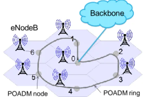
With the evolution of the optical transport technologies, energy-efficient solutions for the transport in the radio access part of cellular backhaul networks have become available. In this paper, we consider the use of a fine granularity optical transport solution: optical slot switching (OSS), an energy-efficient1, low-latency switching technology2 (thanks to optical transparency for transit traffic.), where user packets are encapsulated into fixed duration containers called slots, to interconnect base stations (eNodeBs denoted eNBs) in an LTE-A mobile backhaul network. Here, optical slot switching is applied at the metro level for backhaul networks with a few (and up to a few dozens) of nodes (eNBs): Fig. 1 shows one example of LTE-A mobile backhaul network with eNBs interconnected in a ring structure. We focus on Packet Optical Add/Drop Multiplexer, an implementation of OSS for ring networks.
By shifting the support of User Element (UE) mobility (from one cell to another one) to optical layer, OSS has the potential to dramatically reduce the total handover (HO) duration by 50-70% as shown in3, assuming (conservatively) a queuing delay of 2ms in the OSS backhaul.
In this paper, for the first time, we propose and evaluate four optical transport mechanisms that will effectively support the mobile OSS backhaul to fulfill the afore-mentioned decrease in handover duration. The first two are naive mechanisms. The first naive approach based on slot copy and forwarding, optimizes latency while the second one, based on intermediate re-encapsulation, optimizes capacity. The non naive approaches are adaptive: the first essentially removes the previous trade-off while the second adaptive and CoS-aware is the enabler for an ultra-low latency (<500 µs for real-time, traffic even when it is forwarded), capacity-efficient (above 80%) next generation mobile backhaul network.
Naive traffic forwarding mechanisms
A typical (X2-based) LTE-A handover
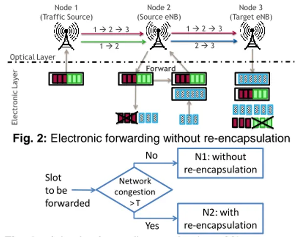
procedure4 is depicted in Fig. 2, where a user receives traffic from Node 1 and is moving from a cell (Node 2) to another cell (Node 3), both served by same service gateway. During handover procedure, the data is first received by Node 2, which forwards it to Node 3. When the handover is complete, Node 1 sends data directly to Node 3.
In an OSS-based LTE-A backhaul, user packets are encapsulated in slots according to their destination eNB. Therefore, slots sent from Node 1 to Node 2 contain user packets with destination Node 2 but also packets that have to be forwarded from Node 2 to Node 3. Information about the intermediate and final destinations of client frames is carried by an out-of-band control channel, which is synchronous with the data channels. Based on this information and without further user packet processing, Node 2 knows which slots should be forwarded. Latency during handover is thus essentially impacted by the forwarding mechanism in the optical layer. Thanks to the ring structure, the optical forwarding mechanisms proposed here also apply to the multicast types of traffic such as IPTV or CoMP5, a cooperation technique that requires cell cooperation and very low latency (1 ms end to end, i.e., less than 500 µs within one access ring) to increase user capacity at cell edges. Such strict latency constraints are enforced in POADM by sending slots even when they are not full upon timer expiration. However this may induce sending partially-full slots and thus network capacity wastage.
Fig. 1: OSS-based LTE-A backhaul network with 7 cells.
eNodeB
POADM ring
Backbone
We now first present 2 naive mechanisms to support mobility directly at the optical layer.
Naive Mechanism N1: Electronic forwarding without intermediate re-encapsulation:
As illustrated in Fig. 2, if an eNB (Node 2) receive a slot containing user packets that should be forwarded to another eNB (Node 3), the slot is 1) received by Node 2; and 2) forwarded without any modification to Node 3, after optoelectronic conversions. The slot is de-capsulated at Node 3, which discards irrelevant packets whose destination is not Node 3.
The advantage of this mechanism is that small channel re-insertion latency is added by Node 2 to mobility traffic. This is done by using a higher priority for forwarded traffic at Node 2. However, since forwarded slots contain user packets which destination is not Node 3, some channel capacity between Nodes 2-3 is wasted.
Naive Mechanism N2: Electronic forwarding with intermediate re-encapsulation:
As illustrated in Fig. 3, and contrary to Mechanism N1, after slots de-capsulation at Node 2, user packets that have to be forwarded to Node 3 are re-encapsulated with user packets sent from Node 2 to Node 3. The advantage of this mechanism is that, since slots sent from Node 2 to the Node 3 contain only user packets with destination Node 3, no capacity is wasted. The disadvantage is that, due to the re-encapsulation at Node 2, forwarded traffic may observe substantial additional latency, which may adversely affect real-time (RT) traffic.
Naive forwarding mechanisms evaluation
We simulate an OSS ring with 7 eNBs each connected to an OSS node (Fig. 1); a selected OSS node (e.g., Node 0) acts as a traffic hub and collects traffic to/from backbone or other rings. Traffic characteristics are shown in Tab. 1. OSS rings are dimensioned to ensure the support of such traffic demand using a custom algorithm. We allocate transponders for each node, starting with the most loaded node
(allocating resources for unicast traffic first at a given node), and use first fit for wavelength allocation. CoS-management is performed by encapsulating RT and non-real-time (NRT) traffics in separated slots, and giving priority to RT slots at the channel insertion. The slot duration is 8 µs, and timers are set to 450 and 900 µs for RT and NRT traffic, respectively. We assume geographically uniform user mobility.
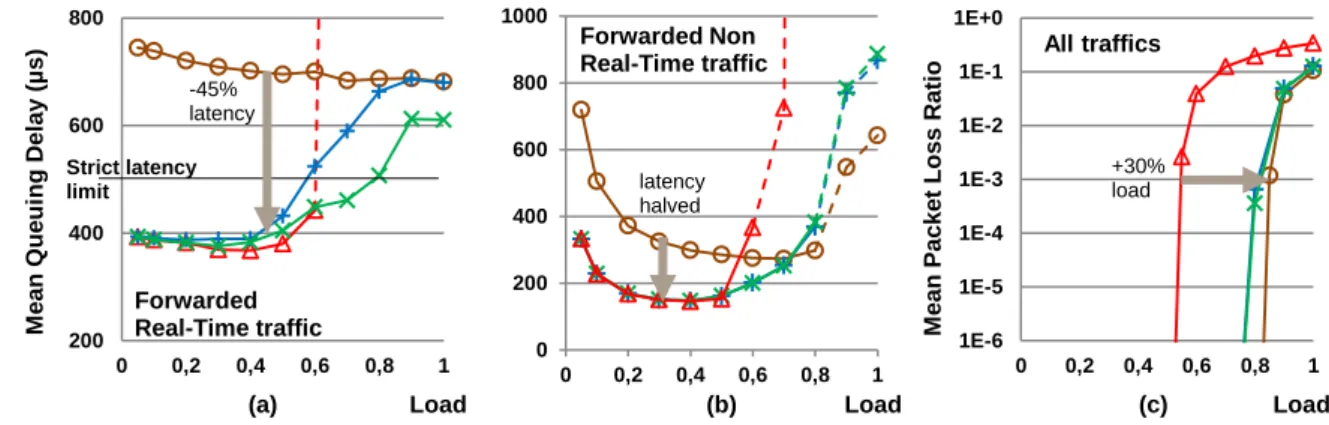
Fig. 5 shows the latency (queuing and insertion) for all four proposed mechanisms, for RT and NRT traffic forwarded by any intermediate node and mean packet loss ratio for all traffics. Load 1 (100%) corresponds to the load for which the dimensioning algorithm is run. The electronic forward mechanism without intermediate re-encapsulation keeps the latency low for the forwarded traffic but causes offered channel capacity waste. As shown in Fig. 5, the maximum supported network load is only ~50% for a packet loss ratio (PLR) below 10-3 (above this limit the netwotk is considered unstable). In contrary, all the offered channel capacity is used (supported load: RT up to 100%, NRT up to 80%) with the forwarding mechanism with intermediate re-encapsulation, at the expense of high latency for the forwarded traffic, which then becomes larger than the 500 µs target for RT traffic even for low loads. This is because the RT forwarded traffic experiences up to 2 RT timer durations: at source and intermediate nodes. (Using lower timer values would reduce latency but also maximum carried load.)
Fig. 2: Electronic forwarding without re-encapsulation
Fig. 4a: Adaptive forwarding mechanisms M3
Node 2
(Source eNB) (Target eNB)Node 3 Node 1 (Traffic Source) El ect ro ni c La yer Optical Layer 1 2 1 2 3 1 2 3 2 3 Forward No Yes Network congestion > T N1: without re-encapsulation Slot to be forwarded N2: with re-encapsulation
Fig. 3: Electronic forward with re-encapsulation
Fig. 4b: CoS-aware adaptive mechanisms M4
El ect ro ni c La yer 1 2 1 2 3 1 2 3 2 3 Optical Layer Node 2 (Source eNB) Node 3 (Target eNB) Node 1 (Traffic Source) Non Real-Time Real Time CoS? Slot to be forwarded M3(T1) M3(T2)
Tab. 1: Traffic characteristics
Type Demand Pattern CoS
Voice 8.5 Mb/s Centralized RT
Data 1.5 Gb/s up,
3 Gb/s down
Centralized NRT CoMP signalling 774 Kb/s Distributed RT CoMP data 1 Gb/s Distributed NRT HO inter-ring 0.1 Gb/s Centralized NRT HO intra-ring 0.1Gb/s Distributed NRT
Advanced traffic forwarding mechanisms
Overall, N1 and N2 trade off network capacity (optimized by N2) for end-to-end latency (optimized by N1.) We propose a third, simple and smarter, mechanism in order to remove this trade-off. This mechanism combines N1 and N2 and selects what forwarding mechanism to use at every slot based on the network load.
Mechanism M3: Adaptive forwarding mechanism
Mechanism M3 is described in Fig. 4a. The re-encapsulation process (N2) is used at Node 2 only when the channel load is high (and network is congested) and capacity should not be wasted. When the channel load is low, N1 is used and capacity (which is then abundant) is leveraged to reduce latency. Because the load is likely to vary in a real network scenario, the re-encapsulation decision is taken dynamically, slot by slot. M3 is distributed: each node independently assesses network congestion by counting the number of slots locally queued for insertion; a pre-defined number of queued slots (threshold T) indicates network congestion.
Mechanism M4: CoS-aware adaptive forwarding
M4 is depicted in Fig. 4b. To further ensure a limitation on latency for very sensitive mobile traffic such as CoMP, we propose to enhance the new adaptive mechanism by introducing two levels of network congestion detection, as shown in Fig. 4b. A first congestion threshold T1 applies to NRT slots, and a second threshold T2>T1 applies to RT slots. This mechanism keeps the latency for forwarded RT traffic as low as possible by saving channel capacity by re-encapsulating NRT forwarded traffic when the network is congested. M4 is also distributed.
Adaptive forwarding mechanisms evaluation
We evaluate the 2 proposed mechanisms using the same scenario described previously, and taking T1=1 slot, T2=40 slots. Using the adaptive forwarding mechanisms the network benefits from each electronic forwarding mechanism depending on the network load: low
latency and high supported load. With M3, the strict latency limit of 500 µs for RT traffic is met for load up to ~55% only. With M4, by differentiating the processing for RT and NRT traffic, we are able to ensure very low latency below 500 µs for the forwarded traffic at low loads and save offered channel capacity at high loads. M4 ensures that RT forwarded traffic meets the latency constraint for load up to 80%, and is generally able to support a total network load of at least 95% with a negligible PLR for RT traffic (all losses reported on NRT traffic thanks to CoS-management. Hence, M4 divides latency by up to factor 2 compared to N2 (Figs. 5a and b) and supporting 30% additional network load compared with N1 (Fig. 5c).
Conclusions
Our proposed CoS-aware adaptive forwarding mechanism presents the best trade-off between latency and offered channel capacity in optical slot switching-based mobile backhaul networks, where eNBs need to forward traffic from one cell to another e.g. upon user element mobility. We ensure a total network supported load of up to 80% while meeting the strict latency constraint of next generation mobile backhaul networks.
Acknowledgement
Work supported by Celtic+ SASER project.
References
[1] Y. Pointurier et al., "Dimensioning and energy efficiency of multi-rate metro networks," IEEE/OSA Journal of Lightwave Technology, vol. 30, no. 22 (2012).
[2] N. Benzaoui et al., “Optical Slot Switching Latency in Mobile Backhaul Networks,” IEEE/OSA Journal of Lightwave Technology, vol. 33, no. 8 (2015).
[3] Q. Wei et al., “Mobility Management in Optical Mobile Network,” Proc. WCNC, p.3130-3135, Istanbul (2014) [4] I. Shayea et al., "Advanced handover techniques in LTE-
Advanced system," Proc. ICCCE, p.74-79, Kuala Lumpur (2012).
[5] Q. Wei et al., ”Multicast in mobile backhaul with optical packet ring,” Proc. WiMob, p.181-188, Lyon (2013).
(a) Load (b) Load (c) Load
Fig. 5: Comparison between electronic forwarding mechanisms N1, N2, M3 and M4. Dashed curves: PLR>10-3.
200 400 600 800 0 0,2 0,4 0,6 0,8 1 M e a n Que ui ng D e la y ( µ s ) Strict latency limit Forwarded Real-Time traffic -45% latency 0 200 400 600 800 1000 0 0,2 0,4 0,6 0,8 1 Forwarded Non Real-Time traffic latency halved 1E-6 1E-5 1E-4 1E-3 1E-2 1E-1 1E+0 0 0,2 0,4 0,6 0,8 1 M e a n Pac k e t Los s R a ti o All traffics +30% load
N2 (with re-encapsulation)