HAL Id: tel-01884431
https://hal.inria.fr/tel-01884431
Submitted on 1 Oct 2018
HAL is a multi-disciplinary open access
archive for the deposit and dissemination of
sci-entific research documents, whether they are
pub-lished or not. The documents may come from
teaching and research institutions in France or
abroad, or from public or private research centers.
L’archive ouverte pluridisciplinaire HAL, est
destinée au dépôt et à la diffusion de documents
scientifiques de niveau recherche, publiés ou non,
émanant des établissements d’enseignement et de
recherche français ou étrangers, des laboratoires
publics ou privés.
Performance for a Programmable Infrastructure
Veronica Karina Quintuna Rodriguez
To cite this version:
Veronica Karina Quintuna Rodriguez. New Network / IT Command: Virtualized Function
Perfor-mance for a Programmable Infrastructure. Networking and Internet Architecture [cs.NI]. Sorbonne
Université, 2018. English. �tel-01884431�
´
Ecole Doctorale EDITE de Paris
Inria - RAP
Nouvelle commande r´
eseau / IT : Performance
des fonctions virtualis´
ees pour une
infrastructure programmable
Par Ver´
onica QUINTUNA RODRIGUEZ
Th`
ese de doctorat en
Sciences de l’Information et de la Communication
Dirig´
ee par Philippe Robert et Fabrice Guillemin
Pr´
esent´
ee et soutenue publiquement le 03 octobre 2018
Devant un jury compos´e de :
M. Andr´e-Luc Beylot IRIT Rapporteur
Mme. Annie Gravey IMT Atlantique Rapporteur M. Fabrice Guillemin Orange Labs Directeur
M. Raymond Knopp Eurecom Examinateur
M. Paul Muhlethaler Inria-EVA Examinateur
M. Herv´e Rivano INSA Lyon Rapporteur
M. Philippe Robert Inria-RAP Directeur
First and foremost, I would like to express my sincere gratitude to my advisors: Dr. Fabrice Guillemin and Dr. Philippe Robert, for their contin-uous guidance and insightful assistance. Without their precious support it would not be possible to conduct this research.
I should thank each and every one of ARC’s team-members, specially Ga¨el Fromentoux and Nicolas Bihannic, for their encouragement but also for promoting me to widen my research from various perspectives. I would particularly like to express my gratitude to Nathalie Labidurie for constantly motivating me.
A special thanks goes to my family, notably my grand parents Miguel and Elena, my aunts Ligia and Alicia, my mom Laura, and last but not least, my brother David and my little sister Tadea.
Keywords: Virtualization, NFV, VNF, queuing systems, resource pooling, Cloud-RAN, C-RAN, parallel programming, processor sharing, cloud computing, scheduling, service chaining.
In the framework of Network Function Virtualization (NFV), we address in this work the performance analysis of virtualized network functions (VNFs), wherein the virtualization of the radio access network (namely, Cloud-RAN) is the driving use-case. The overarching principle of network virtualization consists of replacing network functions, which were so far running on dedicated and proprietary hardware, with open software applications running on shared general purpose servers. The complexity of virtualization is in the softwarization of low-layer network functions (namely, PHY functions) because their execution must meet strict latency requirements.
Throughout this work, we evaluate the performance of VNFs in terms of latency which consid-ers the total amount of time that is required to process VNFs in cloud computing systems. We notably investigate the relevance of resource pooling and statistical multiplexing when available cores in a data center are shared by all active VNFs. We perform VNF modeling by means of stochastic service systems. Proposed queuing models reveal the behavior of high performance computing architectures based on parallel processing and enable dimensioning the required com-puting capacity in data centers.
We concretely investigate the M[X]/M/1 queuing system with Processor-Sharing discipline, for
representing the simultaneous execution of VNF’s jobs through a simple model. We notably consider VNFs composed of a set of parallel runnable jobs forming batches. The execution time of the entire VNF is therefore determined by the runtime of individual jobs. The job’s sojourn time distribution can then be used for dimensioning purposes in order to guarantee that, with a large probability, the service of a job is completed before some lag time.
In the case of Cloud-RAN, the sojourn time of virtualized RAN functions in the cloud must respect tight time budgets. We notably study the runtime of virtual RAN functions by using Open Air Interface (OAI), an open-source solution which implements the RAN functionality in software. In order to reduce latency, we investigate the functional and data decomposition of RAN functions, which leads to batch arrivals of parallel runnable jobs with non-deterministic runtime. To assess the required processing capacity when hosting Cloud-RAN systems, we introduce a bulk arrival queuing model, namely the M[X]/M/C queuing system, where the
batch size follows a geometric distribution. The variability of the fronthaul delay and job’s runtime are captured by the arrival and service distributions, respectively. Since the runtime of a radio sub-frame becomes the batch sojourn-time, we have derived the Laplace transform of this latter quantity as well as the probability of exceeding certain threshold to respect RAN deadlines. We validate by simulation the effectiveness of the M[X]/M/C model while considering
the behavior of a real Cloud-RAN system. For this purpose, we fed the queuing system with statistical parameters captured from the OAI-based Cloud-RAN emulation. Results provide valuable guidelines for sizing and deploying Cloud-RAN systems.
As a proof of concept, we implement an end-to-end virtualized mobile network which notably confirms the accuracy of theoretical models. Performance results highlight important gains in terms of latency. This fact particularly enables increasing the concentration level of VNFs in data centers for achieving CAPEX and OPEX reduction and, moreover, it opens the door to the cloudification of critical network functions.
Abstract ii
List of Figures x
List of Tables xi
Acronyms xii
Introduction xvii
1 Network Function Virtualization:
State of the Art 1
1.1 Virtualization background . . . 1
1.1.1 Virtual Machines . . . 2
1.1.2 Containers . . . 3
1.2 Microservices as an IT paradigm . . . 4
1.2.1 Monolithic and Microservice-based applications . . . 4
1.2.2 Microservices and Component based architectures . . . 5
1.2.3 Microservices and Service Oriented Architectures . . . 5
1.2.4 Implementing microservices within containers . . . 5
1.3 Virtualized Network Functions . . . 6
1.3.1 Formal definition . . . 6
1.3.2 Architectural framework . . . 6
1.3.3 A virtual Network Service . . . 7
1.3.4 Implementing VNFs as microservices . . . 8
1.4 VNFs placement . . . 9
1.4.1 VNFs placement as an optimization problem . . . 11
1.4.2 Multi-site placement by heuristic approaches . . . 11
1.4.3 Multi-provider scenarios . . . 12
1.4.4 Multi-objective solutions . . . 12
1.4.5 Dynamic placement solutions . . . 12
1.5 Resource Sharing . . . 14
1.5.1 Fairness as the basis of resource allocation . . . 14
1.5.2 Mono-resource allocation . . . 15
1.5.3 Multi-resource allocation . . . 16
1.5.4 General Fairness Criterion . . . 19 v
2 VNF modeling 23
2.1 General Assumptions . . . 23
2.2 Use cases . . . 24
2.2.1 Virtualizing packet core network functions . . . 24
2.2.2 Virtualizing wireless network functions . . . 24
2.3 Model description . . . 26
2.3.1 Model settings . . . 26
2.3.2 Representation of a VNF . . . 27
2.3.3 Queuing system formulation . . . 28
2.3.4 Performance Indicators . . . 29
2.4 Scheduling algorithms . . . 29
2.4.1 Allocating the entire macro-function to a Dedicated Core . . . 29
2.4.2 Allocating sub-functions by Round Robin criterion . . . 30
2.4.3 Greedy allocation of sub-functions . . . 30
2.5 Performance Analysis . . . 30
2.5.1 Simulation settings . . . 30
2.5.2 Scheduling performance without reneging . . . 31
2.5.3 Scheduling performance when considering a deadline . . . 31
2.5.4 Analysis of results . . . 33
2.6 A queuing model based on concurrent processing . . . 34
2.6.1 General principles of concurrent computing . . . 34
2.6.2 Model settings . . . 34
2.6.3 Queuing formulation . . . 34
2.6.4 Job’s sojourn time . . . 35
2.6.5 Batch’s sojourn time . . . 38
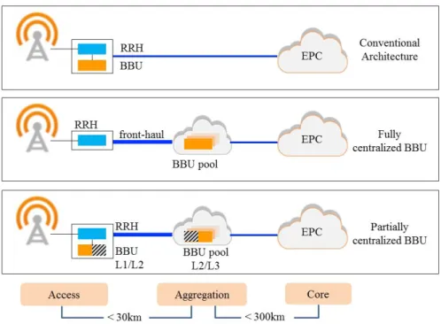
3 Cloud-RAN as an NFV use-case 41 3.1 System description . . . 41 3.1.1 Architectural framework . . . 42 3.1.2 Implementation guidelines . . . 42 3.1.3 Functional splits . . . 44 3.2 Fronthaul analysis . . . 44 3.2.1 Fronthaul size . . . 44 3.2.2 Fronthaul capacity . . . 46
3.2.3 Fronthaul transmission protocols . . . 46
3.2.4 Required capacity per Functional Split . . . 46
3.3 Runtime evaluation . . . 51 3.3.1 Service chain . . . 51 3.3.2 VNF’s runtime . . . 52 3.3.3 Runtime acceleration . . . 54 3.3.4 Performance gain . . . 58 3.4 Worst-case study . . . 59 3.4.1 Worst-case definition . . . 59 3.4.2 BBU-pool analysis . . . 59 3.4.3 Cloud-RAN sizing . . . 61
4 C-RAN modeling for dimensioning purposes 65
4.1 Modeling Principles . . . 65
4.1.1 Modeling data processing . . . 65
4.1.2 Parallelism by UEs . . . 67
4.1.3 Parallelism by CBs . . . 69
4.1.4 No parallelism . . . 69
4.2 Batch model . . . 69
4.2.1 Analysis of the first case . . . 70
4.2.2 Analysis of the second case . . . 72
4.2.3 Main result . . . 72 4.3 Numerical experiments . . . 75 4.3.1 Simulation settings . . . 75 4.3.2 Model analysis . . . 75 4.3.3 Cloud-RAN dimensioning . . . 77 4.3.4 Performance evaluation . . . 77 4.3.5 Analysis of results . . . 78
5 Proof of Concept: C-RAN acceleration 81 5.1 Test-bed description . . . 81 5.2 Implementation outline . . . 83 5.2.1 Encoding function . . . 83 5.2.2 Decoding function . . . 84 5.2.3 Thread-pool . . . 84 5.2.4 Queuing principles . . . 86 5.2.5 Performance captor . . . 86 5.3 Performance evaluation . . . 87 6 Conclusions 89 6.1 Main contributions . . . 89 6.2 Major outcomes . . . 91 6.3 Research perspectives . . . 92 6.4 Publications . . . 92 Appendices 95
A Sojourn time in an M[X]/M/1 Processor Sharing Queue 97
B Cloud-RAN applications 103
C Front-haul capacity reduction for Functional Split I 105
D Resource Allocation Grid 107
E Scheduling Strategy 109
F Analysis of the Markov chain considering an M[X]/M/C system 111
1.1 Virtual and Physical Machine Architectures [1]. . . 2
1.2 Virtual Machine architectures. . . 3
1.3 Container architecture. . . 4
1.4 Monolithic and microservice-based applications. . . 4
1.5 NFV architectural framework [2]. . . 6
1.6 End-to-end network service [2]. . . 7
1.7 Forwarding graph of VNFs [2]. . . 8
1.8 An example of service chaining: Mobile Core Network. . . 9
1.9 Microservices involved in a end-to-end IMS service [3]. . . 10
1.10 Key elements in VNFs placement. . . 11
1.11 CDF of demand-to-slot ratio in slot-based allocations [4]. . . 17
1.12 An example of ‘DRF’ and ‘Asset fairness’ allocations [4]. . . 19
1.13 Jain’s fairness index as a function of α [5]. . . 20
2.1 Network Function Virtualization, use-cases. . . 25
2.2 A VNF as a chain of sub-functions. . . 27
2.3 Architecture of the virtualization environment. . . 27
2.4 VNF modeling: Elements of the queuing system. . . 28
2.5 Scheduling performance considering chained sub-functions. . . 31
2.6 Scheduling performance considering no chained sub-functions. . . 32
2.7 Scheduling performance considering chained sub-functions and reneging. . . 32
2.8 Scheduling performance considering no chained sub-functions and reneging. . . . 33
2.9 Processor-Sharing queue for the modeling of parallelized batch service [6]. . . 35
2.10 Closed integration contour avoiding the real axis [6]. . . 36
2.11 Function x 7→ P(W > x) for different values of the pair (%, q) with load %∗ = %/(1 − q) fixed to 0.8 [6]. . . 37
2.12 Function y 7→ P(V(0)> y) and its asymptotics for large y [6]. . . . 38
2.13 Distribution Dq : x 7→ P(Ω > x) of the batch sojourn time and its approximation [6]. 39 3.1 Cloud-RAN architecture. . . 42
3.2 Cloud-RAN virtualization environment. . . 43
3.3 Cloud-RAN functional splits . . . 44
3.4 HARQ process in Cloud-RAN architectures. . . 45
3.5 Fronthaul radio interfaces according to the various functional splits. . . 47
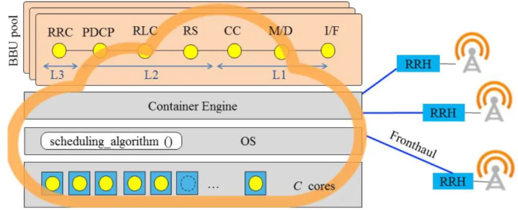
3.6 BBU functions. . . 51
3.7 An example of commercial radio scheduler. . . 52 ix
3.8 Emulated radio resource grid. . . 53
3.9 Runtime of virtual BBU functions (PHY layer, uplink). . . 54
3.10 Runtime of virtual BBU functions (PHY layer, downlink). . . 54
3.11 Functional and data decomposition of BBU functions: Multi-threading model. . . 56
3.12 Radio data units. . . 57
3.13 PHY threading model. . . 57
3.14 MIMO threading model. . . 57
3.15 Channel decoding performance in a single eNB, C = 6. . . 58
3.16 Cloud-RAN processing, worst-case analysis. . . 59
3.17 Channel coding runtime as a function of the MCS, 100 RBs. . . 60
3.18 Downlink workload of a BBU-pool, worst-case scenario. . . 60
3.19 Uplink workload of a BBU-pool, worst-case scenario. . . 61
3.20 BBU-pool performance (10 eNBs), worst-case scenario. . . 62
3.21 Probability density function of channel coding runtime, 10 eNBs, C = 24. . . 63
3.22 Cloud-RAN performance (UL+DL) for real traffic conditions, 10 eNBs. . . 63
3.23 Decoding performance (UL), 10 eNBs. . . 64
3.24 Encoding performance (DL), 10 eNBs. . . 64
4.1 Parallel processing models [7]. . . 66
4.2 Performance of parallel processing systems [7]. . . 67
4.3 Stochastic service system for Cloud-RAN. . . 68
4.4 Two cases upon the arrival of a batch. . . 70
4.5 Statistical parameters of Cloud-RAN. . . 76
4.6 M[x]/M/C behavior. . . . 77
4.7 C-RAN sizing when using the M[X]/M/C model. . . 78
4.8 Cloud-RAN performance, 100 eNBs, C = 151. . . 79
4.9 CDF of the sojourn time of radio subframes. . . 79
5.1 Test-bed architecture. . . 82
5.2 Block diagram of encoding function. . . 83
5.3 Block diagram of decoding function. . . 84
5.4 Multi-threading implementation. . . 85
5.5 Decoding runtime (test-bed). . . 88
5.6 Encoding runtime (test-bed). . . 88
1.1 Example of Dominant Resource Fairness (DRF) resource allocation. . . 18
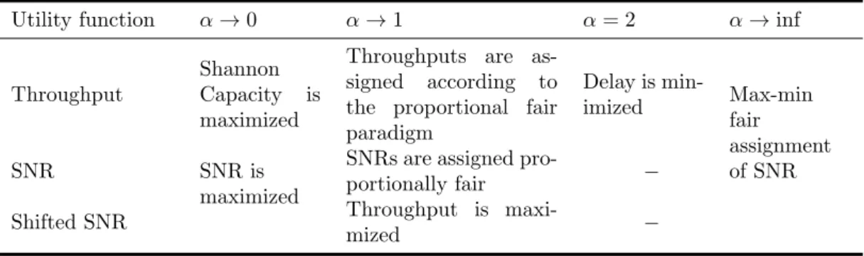
1.2 Generalized α-fair resource allocation in wireless networks: Relation among dif-ferent α- fair allocation for three utility functions. . . 21
2.1 Scheduling performance with chained sub-functions. . . 32
2.2 Scheduling performance with no chained sub-functions. . . 33
3.1 Required fronthaul capacity in a Cloud-RAN system. . . 48
3.2 List of symbols. . . 49
3.3 Loss rate of sub-frames in a BBU-pool of 10 eNBs. . . 62
C.1 Useful RAN bandwidth. . . 105
D.1 Key Features of Modulation and Coding when NRB = 100. . . 107
D.2 MCS and TBS correlation. . . 107
D.3 An example of TBS as a function of NRB. . . 108
ABI Application Binary Interface. ADC Analogic-Digital Converter. AGC Automatic Gain Control.
API Application Programing Interface. ATM Asynchronous transfer mode. BBU Base Band Unit.
BER Bit Error Rate. C-EPC Cloud-EPC. CB Code Block. CBR Constant Bit Rate. CC Channel Coding.
CCDU Channel Coding Data Unit. CCO Core Central Office.
CDC Centralized Data Center. CDN Content Delivery Network. CO Central Office.
CoMP Coordinated Multi-point. COTS Commercial off-the-shelf. CP Cyclic Prefix.
CPRI Common Public Radio Interface. CPU Central Processing Unit.
CQI Channel Quality Indicator. CRC Cyclic Redundancy Check. CU Central Unit.
DC Dedicated Core. Diah Diameter handler. DL downlink.
DRF Dominant Resource Fairness.
DRFH DRF in Heterogeneous environments. DU Distributed Unit.
e2e end-to-end. eCPRI evolved CPRI.
EM Element Management.
eMBB enhanced Mobile Broad-Band. eNB Evolved NodeB.
EPC Evolved Packet Core. EPCaaS EPC as a Service.
ETSI European Telecommunications Standards Insti-tute.
EUTRAN Evolved Universal Terrestrial Radio Access Net-work.
FCFS First-come, First-served. FDD Frequency Division Duplex. FFT Fast Fourier Transform. FG Forwarding Graph. FIFO First In Firs Out. FS Functional Split.
G Greedy.
gNB next-Generation Node B. GPP General Purpose Processor. GPU Graphics Processing Unit.
HARQ Hybrid Automatic Repeat-Request. ICIC Inter-Cell Interference Coordination. IFFT Inverse Fast Fourier Transform. ILP Integer Linear Programming. IMS IP Multimedia Subsystem. IoT Internet of Things.
IPC Inter process communication. IQ In-Phase Quadrature. ISA Instruction Set Architecture. ISI Inter-symbol interference. ISP Internet Service Provider. IT Information Technology. JVM Java Virtual Machine. KPI Key Performance Indicator. LLR Log-Likelihood Ratio. LTE Long Term Evolution.
MANO Management and Orchestration. MCO Main Central Office.
MCS Modulation and Coding Scheme. MEC Multi-access Edge Computing. MILP Mixed Integer Linear Programming.
MIQCP Mixed Integer Quadratically Constrained Pro-gram.
MNO Mobile Network Operator. NAT Network Address Translation.
NBS Nash Bargaining Solution. NF Network Function.
NFV Network Function Virtualization. NFVI NFV Infrastructure.
NFVO NFV Orchestrator. OAI Open Air Interface.
OFDM Orthogonal Frequency Division Multiplexing. ONAP Open Networking Automation Platform. OS Operating System.
OTT over-the-top.
PAPR Peak-to-average power ratio. PDCP Packet Data Convergence Protocol. PM Physical Machine.
PMD Polarization Mode Dispersion. PoP Point of Presence.
PRB Physical Resource Blocks. QCI QoS Channel Indicator. QoE Quality of Experience. QoS Quality of Service. RAM Random Access Memory. RAN Radio Access Network. RANaaS RAN as a Service.
RAT Radio Access Technologie. RB Resource Block.
RE Resource Element.
REST Representational State Transfer. RLC Radio Link Control.
RoE Radio over Ethernet.
RR Round Robin.
RRH Radio Remote Head.
RSC Recursive Systematic Convolutional. RTT Round Trip Time.
SC-FDMA Single Carrier Frequency Division Multiple Ac-cess.
SINR Signal-to Interference Noise Ratio. SISO Single Input Single Output. SLA Service Level Agreement. SNR Signal Noise Ratio.
SOA Service Oriented Architecture. TB Transport Block.
TBS Transport Block Size. TDD Time Division Duplex. TTI Transmission Time Interval. UE User Equipment.
UL uplink.
URLLC Ultra-Reliable Low-Latency Communications. vBBU virtualized BBU.
vEPC virtual Evolved Packet Core. VIM Virtualised Infrastructure Manager. VM Virtual Machine.
VMM Virtual Machine Monitor. VNF Virtualized Network Function. VNF FG VNF Forwarding Graph. VNFC VNF Component. VNFM VNF Manager.
VNO Virtual mobile Network Operator. VRRM Virtual Radio Resource Management. WFQ Weighted Fair Queuing.
Problem Statement
The great diversity of network services and applications are pushing network operators to con-stantly update and upgrade their infrastructures. These evolutions entail continual growth of CAPEX and OPEX. The required fast deployment is not compliant with the current network in-frastructure based on proprietary hardware. Network inin-frastructures require today complex op-erations and manual configurations making them difficult to update and maintain. Inter-working between diverse network environments is also an important weakness of current infrastructures. These issues cannot be easily solved without renewing network architectures. Network Function Virtualization (NFV) [2] offers a new way of designing, deploying and managing networking services.
NFV precisely consists of replacing network functions, which were so far running on dedicated and proprietary hardware, with open software applications running on shared Commercial off-the-shelf (COTS) servers in cloud platforms. NFV promises great economic savings and time-to-market acceleration, as well as more flexible and accurate management of resources. However, deploying on-demand networks and upgrading services on the fly requires the adoption of modern IT solutions including adapted development patterns and optimized software models.
The overarching principle of virtualization is to host network functions on one or more vir-tual units (Virvir-tual Machines (VMs) or containers). Virvir-tualized Network Functions (VNFs) are deployed on top of a virtualized infrastructure, which may span over more than one physical location and even over a cloud computing infrastructure. Ideally, VNFs should be located where they are the most efficient in terms of performance and cost. VNFs can be placed in data cen-ters, network nodes or even in end-user devices depending on the required performance (notably latency) and resources (bandwidth, storage and computing). The cloudification and commoditi-zation of network functions, however, brings new challenges, especially when virtualizing wireless access networks.
The performance evaluation of VNFs is essential for designing software-based networks as performance models determine engineering rules for the deployment of future virtualized infras-tructures. The challenge is to develop models for designing infrastructures that combine both software defined networks and cloud platforms.
Main objectives
The main goal of the present PhD thesis is to highlight performance models for virtualized network functions in order to develop engineering rules for their deployment. This includes:
- Determining a driving use case.
- Identifying Key Performance Indicators (KPIs) that reflect the behavior of virtualized network functions.
- Defining KPI-based slicing rules in order to decompose a global network function into elementary components.
- Evaluating the performance of virtualized network functions taking into account the schedul-ing strategy of internal resources.
- Validating theoretical models by means of a use case implementation.
Thesis outline and document structure
This thesis begins with a thorough survey of the state of the art presented in Chapter 1. This sur-vey considers both academic and industrial studies in terms of Network Function Virtualization (NFV) and resource allocation. We present in Chapter 1, a deep analysis of various virtu-alization technologies while considering both container- (e.g., Docker) and VM-based systems (e.g., OpenStack). Modern Information Technology (IT) paradigms, namely microservices-based applications, are particularly introduced for gathering relevant implementation guidelines. Be-yond the study of the virtualization concept and the formal definition of VNFs, we discus in this chapter, the problem of VNFs placement which basically determines where and how the building blocks of a virtualized network service are instantiated. Finally, we examine various resource allocation and scheduling strategies in the aim of abstracting fair sharing tenets.
In Chapter 2, we study the VNF modeling as a chain of components (or microservices) in the perspective of deriving execution principles on multi-core platforms. VNFs are executed on the top of the virtualization layer while sharing the available computing resources. A global scheduler is in charge of allocating the capacity of servers. In order to evaluate the VNF performance in terms of latency, we concretely address the evaluation of various scheduling strategies. At the end of this chapter, we pay special attention to the ‘Processor Sharing’ discipline; we concretely model the simultaneous execution of VNFs’ components by a queuing system with batch arrivals. We define the virtualization and the cloudification of Radio Access Network functions (Cloud-RAN) of mobile networks as the driving use-case of this study. Cloud-RAN aims centralizing the base-band processing of radio signals while keeping distributed antennas. To achieve the performance evaluation of Cloud-RAN systems, and notably numerical experiments, we use Open Air Interface (OAI), an open-source solution which implements the RAN functionality in software.
A thorough study of Cloud-RAN systems is carried out in Chapter 3. Since radio access networks must meet strict latency constraints, we particularly analyze the runtime of software-based RAN functions in the aim of identifying bottlenecks. We notably propose in this chapter, a parallel processing model to reduce latency when executing virtualized RAN functions in the cloud. Finally, to gather a first approach for Cloud-RAN sizing (i.e., determining the required computing capacity to host the RAN functionality of a given number of base stations) we carry out a worst-case analysis.
The problem of dimensioning Cloud-RAN infrastructures is concretely addressed in Chap-ter 4. We introduce a batch queuing model, namely the M[X]/M/C multi-service system, to assess the needed processing capacity in a data center while meeting the RAN latency require-ments. We specially study two scheduling strategies of parallel runnable RAN jobs.
As a proof of concept, we have implemented the proposed models in an OAI-based test-bed platform. Performance results as well as implementation principles are presented in Chapter 5. Conclusions and main contributions are finally summarized in Chapter 6.
Chapter
1
Network Function Virtualization:
State of the Art
Contents
1.1 Virtualization background . . . 1 1.2 Microservices as an IT paradigm . . . 4 1.3 Virtualized Network Functions . . . 6 1.4 VNFs placement . . . 9 1.5 Resource Sharing . . . 14
The emergence of virtualization technology plays a crucial role in the evolution of telecom-munications network architectures, notably by enabling the virtualization of network functions. This is clearly a groundbreaking evolution in the design of future networks and IT infrastruc-tures, which can eventually be completely merged.
The convergence of IT and Telecom involves fundamental transformations in the way that telcos conceive, produce and operate their services. Virtualization incites network operators to redefine their business models by taking inspiration from modern IT solutions such as virtualized and microcroservices-based applications. These emerging concepts are being adopted by over-the-top (OTT) players such as Amazon or Google.
The separation of software from hardware gives rise to resource sharing mechanisms where centralized hardware can carry out diverse network functions according to network traffic and customer needs. Following a formal study of emerging IT paradigms as well as of the framework of NFV, we address in this chapter both the VNF’s placement problem and the relevance of resource pooling.
1.1
Virtualization background
In a strict sense, virtualization is the process of creating a virtual version of a physical machine. This concept is specially relevant in cloud computing markets where data centers offer the possibility of reserving computing and storage resources to individual or business customers.
The virtualization technology brings multiple benefits, the major advantage is notably the efficient utilization of resources (memory, network, computing) by means of resource sharing1,
i.e., physical resources are shared among the active virtual machines. Thus, the resource pooling of physical infrastructures dynamically enables the allocation of the capacity of servers according to needs instead of dedicating resources even when they are not used.
Beyond cost savings in capital and operation expenditures, virtualization enables agility, portability, and flexibility when deploying software applications. Switching over to a virtualized environment shall provide more efficient IT operations, specially when installing and maintaining software applications. Another great advantage of virtualization is the business continuity. Cloud customers can access their data and applications anywhere. In addition, virtualization makes disaster recovery much more accurate due to the facility of restoring services by means of system images whose backups are stored in the cloud.
1.1.1
Virtual Machines
Virtual Machines (VMs) were originally defined in 1974 by Popek and Goldberg [8]. They define a VM as ‘an efficient isolated duplicate of a real machine’. They perform these notions by means of the so-called Virtual Machine Monitor (VMM) which provides the following key features: (i) ‘essentially identical’ environment, where any program running in a virtual machine should exhibit the same behavior as that performed on the physical machine; (ii) ‘efficiency’, where applications running in a virtual environment show at worst only minor performance reductions in terms of latency; and (iii) ‘resource control’, where the VMM is assumed to have complete control of system resources (memory, peripherals, computing, storage). The authors finally consider, a VM as the environment created by the VMM.
Virtual Machine Architecture
The VM’s architecture can be defined from a process and system perspective depending on the virtualization level. While a ‘process VM’ simulates the programming environment for the execution of individual processes, the ‘system VM’ emulates the hardware and supports the execution of an operating system. See Figure 1.1 for an illustration.
(a) Physical Machine (b) Virtual Machines
Figure 1.1: Virtual and Physical Machine Architectures [1].
Process VM: From the perspective of a process, a virtual machine consists of an address space, and user-level instructions that allow the execution of a single user process. The only way that a process can interact with the I/O peripherals is through the operating system. Thus, in a ‘process VM’, virtualizing software translates a set of OS instructions and composes a
virtual embedded platform where Application Binary Interfaces (ABIs) enable the interaction between the process and the virtual machine. A ‘process VM’ exists only to support a process, it is created when the process begins and is deleted when the process terminates [1]. The most popular example of a process VM is the Java Virtual Machine (JVM).
System VM: When considering a ‘system virtual machine’ it supports the entire system where various processes can run simultaneously. Smith and Nair define in [1] a system VM as a persistent system environment that supports an Operating Systems (OSs) and various system processes. As shown in Figure 1.1, it provides the access to virtual hardware resources including I/O peripherals, storage and computing by means of a ‘guest Operating System (OS)’. The VMM emulates the hardware via the Instruction Set Architecture (ISA), i.e., provides virtualized resources.
The process or system that runs on a VM is known in the literature as ‘guest’, while the underlying platform that supports the VM is the ‘host’ [1].
System Virtual machines running on a shared physical hardware need to be managed and monitored by a specialized entity, namely the Virtual Machine Monitor (VMM) (also known in the literature as ‘hypervisor’). As shown in Figure 1.2, there are two kinds of hypervisors, native and hosted ones. While the first one runs directly in the bare-metal machine, the hosted hypervisor runs as an application on the top of the operating system while VMs are seen as individual processes [9].
Figure 1.2: Virtual Machine architectures.
Bare-metal hypervisors: They are booted as a machine operating system and perform the complete control of physical resources. The various VMs run as system processes and maintain each of them their owner guest OS [9]. Examples of native hypervisors are Xen and VMware ESX.
Hosted hypervisors: They run on top of operating systems and are themselves a system process. As in bare-metal hypervisors, VMs maintains their owner guest OS, providing the illusion of a private hardware environment. KVM is an example of this type of VM, however, it maintains certain kernel modules that convert the host OS to a bare-metal hypervisor [9].
1.1.2
Containers
Containers were originally created in 2000s for security purposes, as a way of separating envi-ronments that could be shared by multiple users. In fact, the first Linux systems maintained isolated partitions or subsystems (also know as jails) [10] where the access to file systems and networking is virtualized.
Advancements in Linux ‘namespaces’ provided the next step for containers. In fact, user namespaces allow the isolation of Linux environments where users and groups may have privi-leges for certain operations inside a given container and do not outside it [11].
Figure 1.3: Container architecture.
Containers can then be described as Operating System (OS) level virtualisation, where the OS itself creates a Virtual Environment that provides all needed resources and files to support the processes. While VMs require a complete OS for running processes, containers require only the associated libraries needed by that process [10]. By providing an image that contains all applications’ dependencies, containers are portable and consistent [11]. As shown in Figure 1.3, various containers can share a single operating system, then applications and services stay lightweight and run swiftly in parallel [11].
1.2
Microservices as an IT paradigm
Historically, there have been several trends that have incited application architects to find better ways to build systems. Software applications have been designed using objects, components, libraries, and services. Several patterns like Model View Controller, multi-tier architectures, and the widely used client-server architectures have improved the performance in execution time as well as in deployment time. Some efforts have been made in software industry, and “Microser-vices” were born as a way of designing software applications as suites of independently deploy-able services each running in its own process and communicating with lightweight mechanisms. Microservices architecture shall provide agility, robustness, and scalability to software-based network functions [12].
1.2.1
Monolithic and Microservice-based applications
While a monolithic application puts all its functionality into a single process and scales by replicating the monolith on multiple servers, a microservice-based one puts each element of functionality into a separate service and scales by distributing these services across servers, replicating as needed [12], see Figure 1.4 for an illustration.
Main features of microservices
- A microservice need to be treated as a product, it must be small enough to be focused on a single task. In most cases, each task represents a small business capability, e.g., a network function or sub-function [13].
- Microservices are loosely coupled and have a bounded context, i.e., they ignore everything about implementation or architecture of other microservices [13].
- Microservices can be developed in any programming language. They communicate with each other by means of neutral-language Application Programing Interfaces (APIs), e.g., Representational State Transfer (REST) protocols [13].
- Microservices maintain high availability while providing isolation and scalability. The uptime of each service contributes to the overall availability of applications [14].
1.2.2
Microservices and Component based architectures
The idea of breaking monolithic applications into components were presented several years ago. At one point objects have been the substitutes of components and then objects have come back to components again. “A component is something independently replaceable and independently upgradeable” [12]. In terms of software we can see components in two ways, libraries and services. Libraries can be defined as components that are linked into a program and called using in-memory functions while a service is a different kind of component that is running in its own process [12]. When building communication structures between the various components or services, communication approaches put significant ‘smart’ into the communication mechanism itself, e.g., the Enterprise Service Bus (ESB). In a microservice-based architecture, requests and responses use simple REST protocols rather than complex protocols managed by a central tool [12, 14].
1.2.3
Microservices and Service Oriented Architectures
The microservice-based architecture is a kind of Service Oriented Architecture (SOA) [15]. Al-though both deals with services, unlike SOA, microservices are not focused on re-usability. Microservices are built in the aim of enabling the continuous evolution of services and of making systems easier to manage.
1.2.4
Implementing microservices within containers
As presented in [14], the convergence of the evolution of both software architectures and com-puting infrastructures gives rise to the microservices-based paradigm. The goal of emerging trends as virtual machines or containers has always been to minimize the consumption of phys-ical resources while enabling scalability by means of the replication of these units (VMs, or Containers). Container-based and notably unikernel-based applications abstract the host OS and implement only the needed dependencies and libraries to function, which enable granular scalability and notably the implementation of microservices. Microservices are already being proposed by cloud service providers (e.g.,‘Iron.io’) by means of containers-based solutions [14].
1.3
Virtualized Network Functions
1.3.1
Formal definition
The NFV concept was introduced by a group of network service providers in 2012 and has been promoted by the European Telecommunications Standards Institute (ETSI) Industry Specifica-tion Group for Network FuncSpecifica-tion VirtualizaSpecifica-tion [16].
NFV enables decoupling network functions from integrated hardware and moving them to virtual servers. A VNF is nothing but a software application, which can be instantiated on the fly and executed in general purpose computers. In this way, network functions are not embedded in hardware but designed as applications. These applications could run on virtualized or physical environments made of off-the-shelf hardware. The functional decoupling allows a separated evolution of hardware and software and a faster deployment of new services over an already installed physical infrastructure.
1.3.2
Architectural framework
The operation of Virtualized Network Functions (VNFs) requires a dynamic architectural frame-work which provides access to shared hardware and virtual resources. The NFV Frameframe-work is defined in [2] and illustrated in Figure 1.5.
Figure 1.5: NFV architectural framework [2].
VNFs are decoupled from hardware infrastructure by the virtualization layer. Physical re-sources notably computing, networking and storage are shared by all software-based network functions which run in the top layer of the virtualization platform.
As presented in [2], the VNF life-cycle is managed by the Management and Orchestration (MANO) domain, which also performs the orchestration of physical and virtual resources re-siding in the so-called NFV Infrastructure (NFVI). To be more specific, the NFV Orchestrator (NFVO) manages the virtualisation infrastructure and carries out end-to-end (e2e) network ser-vices while multiple VNF Managers (VNFMs) perform the instantiation, update and scaling of
individual VNFs in interaction with their Element Managements (EMs). The Virtualised Infras-tructure Manager (VIM) is in charge of both resource allocation procedures (e.g., hypervisors) and the deployment of virtualisation enablers (e.g., VMs onto hypervisors). Meta-data, service descriptors and deployment templates of VNFs reside in the ‘Service, VNF and Infrastructure Description’ entity.
1.3.3
A virtual Network Service
Service chaining
A virtualized end-to-end network service can be conceived as a Forwarding Graph (FG)’ [2] of Network Function (NF) which is also known in the literature as ‘Service Chaining’. The performance of the whole service is given by the aggregation of individual performances. In other words, a network service is nothing but a chain of virtual network functions interconnected between them by logical links. See Figure 1.6 for an illustration.
Figure 1.6: End-to-end network service [2].
The granularity of functional blocks composing the Forwarding Graph (FG) of VNFs, as well as, the geographic location of each VNF, need to be determined by network architects according to the service and performance requirements. Figure 1.7 illustrates an e2e service formed by a serial chain of VNFs (V N F − 1, V N F − 2, V N F − 3) where the second one is itself decomposed in three functional blocks denoted as V N F − 2A, V N F − 2B, V N F − 2C.
To be more specific, a VNF can be instantiated in a single VM or by means of multiple centralized or distributed virtual servers. A VNF can be formed by various internal components, where each single element can be executed on a VM. In the same way, a single VM can host multiple VNF’s components or even various VNFs. As a consequence, Virtual Network Functions can be spread across several network sites.
In this context, VNFs composing the end-to-end service can be distributed along different physical locations (namely, Point of Presences (PoPs) of network operators). The ensemble of PoPs constitutes then the NFVI, i.e., ‘the totality of hardware and software components which build up the environment in which VNFs are deployed, managed and executed’ [2].
An example of service chaining
The service chaining of the 5G Mobile Core Network (namely, Evolved Packet Core (EPC) in 4G) is a good candidate for virtualization. As shown in Figure 1.8, several network functions such as user authentication, user authorization, context management, session management, among others, can be executed as a chain of components in general purpose servers, i.e., in a data center. Other examples of service chaining are the path of functional blocks of a web service (firewalls,
Figure 1.7: Forwarding graph of VNFs [2].
Network Address Translation (NAT) servers, and load balancers), the existing network functions within Content Delivery Networks (CDNs), IP Multimedia Subsystems (IMSs), or even the chain of base-band processing in Radio Access Networks (RANs).
1.3.4
Implementing VNFs as microservices
From a modeling point of view, a Microservice can be typically mapped to a mono-VNF or even to a single VNF Component (VNFC), which can be hosted either in a dedicated light-weighted virtualization environment e.g., a container, or in a shared virtualized system where physical resources are common with other microservices.
The first approach (dedicated) does not have any significant impact on the NFV architectural framework, while the second one (shared) requires separating the life-cycle management of VNF instances from the life-cycle of the virtualization environment. In both cases, the mono-VNF nature of microservices might reduce or eliminate the role of the VNFM. The major advantage of microservices is that they make possible the promises of NFV notably in terms of agility, scalability and robustness.
A network service as a chain of microservices
An end-to-end network service can be seen as a chain of microservices. Network functions and sub-functions can be either fully distributed into a cloud-based computing system or centralized in a node-based infrastructure. Potvin et al. propose in [3], a distributed software architecture enabling the deployment of a single software version of a microservice on multiple heteroge-neous cloud platforms. Thus, microservices can be distributed and combined without location restrictions on VMs in order to efficiently use the available resources.
This is an advantage compared to a Node-based deployment where functionality of microser-vices is bound to specific physical resources (dedicated hardware or VM). The authors employ as driving use-case the service chaining of an IP Multimedia Subsystem (IMS), which is shown in Figure 1.9. The first microservice involved in a service setup scenario is the SIP Handler, which implements the session initiation functions of the call session control function. It uses the Node selector service for determining the VNF placement, i.e., where the call session microservice
Figure 1.8: An example of service chaining: Mobile Core Network.
must be instantiated.
The microservice denoted by ‘C’ performs the functionally of a call session control function. It builds the appropriate service chain to provide the requested service. The C unit is instantiated on-demand and is terminated when the service is completed; during a call, it remains active until the SIP bye message is acknowledged.
The microservice ‘H’ is used for getting the subscriber profile. It is then responsible for querying the HSS database. The microservice ‘Diameter handler (Diah)’ is an interface that implements the diameter protocol towards the HSS. The main function of the microservice ‘A’ (anchor point controller) is to negotiate the media codec for assuring the exchange with the media processor unit. Telephony Server ‘T’ provides telephony related features to the Subscriber like ad-hoc conferences. Finally, the microservice ‘M’ provides point-to-point connectivity for performing calls in both directions.
The above use-case highlights key factors to take into account when virtualizing network services such as: (i) the resource allocation mechanism, notably when performing node-based systems due to the static assignation of computing and storage resources; (ii) scheduling algo-rithm when performing distributed cloud-based approaches. Performance degradation can be experimented when runnable processes wait for accessing resources. Performance results when comparing node-based and cloud-based approach evidence the relevance of resource sharing for saving resources.
1.4
VNFs placement
The placement problem or more precisely the resource allocation problem has been widely studied in the literature in the framework of cloud computing. These studies consider either ‘static’ or ‘dynamic’ allocation of memory, storage and computing capacities in the aim of hosting software applications in data centers while optimizing resource utilization and guaranteeing the proper operation of services.
Figure 1.9: Microservices involved in a end-to-end IMS service [3].
The various VNFs composing an end-to-end service can eventually be placed at different geographic locations. Beyond computing and memory resources, the problem of VNFs placement requires to consider the capacity (bandwidth) of links connecting data centers with each other.
As shown in Figure 1.10, the key elements when assigning VNFs to data centers are: - Network topology of data centers. For instance, a realistic topology may consider the
Point of Presences (PoPs) of network operators which are generally distributed within the aggregation and core network segments. See for instance the three-level hierarchy proposed in [17];
- Availability of resources: storage, memory, computing, networking;
- Performance requirements of the end-to-end network service notably in terms of latency; - Service chaining, i.e., when considering a virtual network service as a chain of components
(e.g., VNFs).
When placing VNFs, the major challenge is to consider all the above-mentioned key elements. However, most contributions in this respect only consider certain elements together. We classify placement strategies as follows:
- By the nature of the placement in ‘static’ and ‘dynamic’. While static solutions know in advance the set of requirements (VNFs), dynamic ones consider allocating resources on the fly at each request arrival.
- By the optimization goal when seeking load balancing among data centers, cost savings (e.g. when minimizing the number of used data-centers), guaranteeing service requirements (notably in terms of latency), or even end-to-end latency reduction (e.g., when allowing over-provisioning of resources).
- By the number of resources in mono-resource and multi-resource.
- By the number of sites in mono-site (a single geographic location with multiple servers) and multi-site (distributed data centers).
- By the type of request in mono-VNF and multi-VNF. This latter considers a request being composed of a chain of VNFs performing an end-to-end network service.
Figure 1.10: Key elements in VNFs placement.
1.4.1
VNFs placement as an optimization problem
Recent research efforts have addressed the VNFs placement as an optimization problem which looks for load balancing among data centers while minimizing the resource utilization (band-width, computing, memory, storage) and guaranteeing the performance requirements of network services (e.g., latency). Placement algorithms basically determine where and how the building blocks of a virtualized network service are instantiated.
The drawback of optimization approaches is that they require knowing the workload of requests ‘a-priori’ to provide the optimal solution, i.e., for mapping VNFs to hosting data centers. Nevertheless, when considering network services the workload varies according to traffic fluctuations, then placement and resource allocation need to be adapted on the fly.
To react quickly to changes in demands, optimization-based approaches search to minimize the convergence time of algorithms. For instance, in [18], the authors propose an optimization algorithm which gives a solution within 16 seconds for small service provider scenarios; however, the algorithm runtime linearly increases when augmenting the number of requests. The authors notably consider a NFV burst scenario where dedicated hardware becomes fully utilized and the spillover is handled by means of public cloud resources. The proposed model, called VNF-P for VNF placement, is implemented as an Integer Linear Programming (ILP).
1.4.2
Multi-site placement by heuristic approaches
In order to cope with large infrastructures, most placement models propose heuristic procedures for efficiently reaching near-optimal solutions. See for instance [19–22].
Unlike [18], the authors in [19, 21] consider the end-to-end delay of network services. In [19] resource allocation is performed by preventing over or under provisioning of resources and no-tably by guaranteeing end-to-end latency requirements. The authors model the VNFs placement problem as an ILP and propose a heuristic procedure for delivering results in a timely manner.
The problem is decomposed into three phases (i) determining the required number of VNF’s instances (e.g., firewalls) to meet the service demand and placing them in the infrastructure (namely, PoP), (ii) assignment of service flows, i.e., VNF’s instances are assigned to service flows and (iii) chaining VNFs, i.e., creating paths that interconnect previously placed network functions. This latter takes into account two crucial factors, namely end-to-end path latency and distinct processing delays added by different virtual network functions. The heuristic approach is evaluated while using realistic infrastructure topologies (namely, Internet Service Provider (ISP) environments of up to 50 PoPs), and small service chaining scenarios of up to 3 blocks. Results show that the ILP model leads to a reduction of up to 25% of the end-to-end latency notwithstanding 4% of resources over-provisioning.
A similar approach is presented in [23]. Here, the optimization criterion is based on CAPEX and OPEX cost. The model determines the optimal number of VNFs and where to place them. The algorithm knows a-priori the network topology, the set of middle-box specifications and the traffic requests.
1.4.3
Multi-provider scenarios
Dietrich et al. propose in [24], an approach for multi-provider network service embedding, where the placement of network functions takes into account the limited geographic footprint of providers. The main goal is to satisfy both customer and provider needs while improving the Quality of Experience (QoE) and maximizing revenues, respectively. The authors introduce a service model that simplifies the estimation of computing and bandwidth requests in service chains. They propose an orchestrator, called Nestor, which performs efficient VNFs placement on the basis of topology abstraction for obfuscating confidential information of network functions providers. In a first time, the orchestrator assigns network functions to data centers operated by multiple providers. Then, the assignment of network sub-functions to servers is carried out on the basis resource availability and network topology. The authors employ ILP for mapping network function to multi-provider data centers and heuristic algorithms for allocating servers to network sub-functions.
1.4.4
Multi-objective solutions
Addis et al. in [25] provide a multi-objective placement model which aims at minimizing the utilization of links and the total virtualization cost at the NFVI layer. The authors formulate the model as a Mixed Integer Linear Programming (MILP) which requires 15 minutes on average, to find an optimal solution. The algorithm is evaluated in underload conditions, on a realistic network topology which considers access, aggregation, and core networks. The capacity of links is limited and takes different values at each network level. The system takes into account two type of VNFs: tunneling and firewall. The end-to-end latency of the virtual network service and the runtime of VNFs are also considered. Results show that for strict end-to-end latency requirements the utilization of links is increased. On the contrary, when minimizing the link utilization, ‘tunneling VNFs’ (which increase the bitrate) are placed at the aggregation level and ‘firewall VNFs’ at the access and core levels.
1.4.5
Dynamic placement solutions
Mono-site resource allocation
Despite the VNFs placement problem is widely studied in the literature, few works consider the dynamic allocation of cloud resources (network, computing, storage), i.e., assigning request on the fly. A dynamic approach is presented in [26]. This work introduces a high-level orchestrator
for managing the resource allocation of Poisson-based request arrivals. Virtual nodes and virtual links are created and destroyed depending on traffic conditions for achieving adaptive resource utilization.
The placement decision takes into account the system load by means of a monitoring en-tity. Performance results are carried out in a mono-site test-bed of 4 hosts while evaluating three placement strategies (namely, optimization goals): (i) load balancing when choosing the least used host, (ii) energy savings while grouping requests in order to allocate them in a single host, and (iii) improving QoS while choosing the least busy host. Results notably demonstrate that placement solutions strictly depend on optimization goals, also referred to as ‘placement engine’. This claim is consistent with results presented in [27], where the authors perform a trade-off between different optimization objectives, as well as with the multi-objective strate-gies introduced in [28] where the authors propose a specific algorithm for each optimization goal (namely, minimizing the number of Physical Machine (PM), load balancing) and even for each optimization scenario (namely, static or dynamic) by means of a three-dimensional vector approach hCPU,RAM,I/Oi. Unlike [26], [27] uses a Mixed Integer Quadratically Constrained Program (MIQCP) model for mapping VNFs to data-centers.
Multi-site adaptive placement
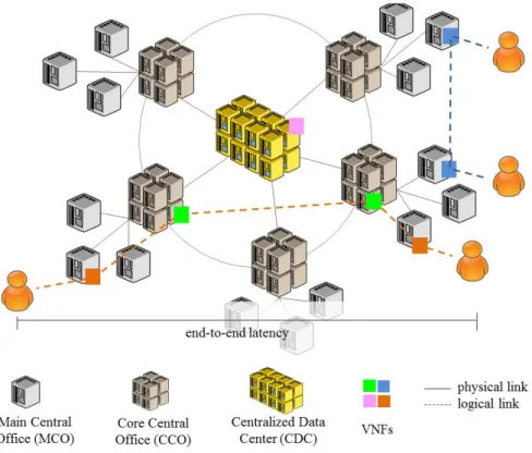
A dynamic adaptive placement of VNFs is presented in [17]. The placement strategy is notably based on both the state of data centers (which consider the load in terms of computing and memory) and the latency requirements of VNFs. The proposed strategy notably favors the placement of critical VNFs in terms of latency near to end-users. Offloaded VNFs are installed higher in the network. The offloading decision is taken on the basis of a ‘target’ threshold which is automatically adjusted according to the arrival rate of the various types of requests. An arriving request is accommodated in a data center when the average of occupied resources does not exceeds the ‘target’. The target threshold is dynamically adapted by a classical hysteresis principle. When the average load of a given data center exceeds the maximal threshold, the target is reduced to favor deflections. Similarly, when the average load is under the minimal threshold, the target is increased to reduce deflections.
The model considers distributed data centers within a three-level hierarchy: Main Central Offices (MCOs), Core Central Offices (CCOs) and Centralized Data Centers (CDCs). The capacity of data-centers varies at each level. The authors evaluate the proposed strategy while considering two types of requests which arrive according to a Poisson process: (i) data plane functions which must be placed only in MCO due to strict latency constraints, (ii) control plane functions and Multi-access Edge Computing (MEC) applications which are delay tolerant and may be located anywhere. Despite service chaining is not considered, the authors evaluate the proposed solution against mechanism implemented in OpenStack and Open Networking Automation Platform (ONAP) while notably considering the blocking rate of VNFs (e.g., when data centers are not able to host more VNFs). Results show that the proposed algorithm improves the performance in terms of acceptance of VNFs. Another proposition of placement when using OpenStack is presented in [21].
Anticipated offloading of resource-specialized requests
Thompson et al. in [29] present a cooperative scheme in the framework of multi-resource cloud computing as an extension of their previous works which consider single resource sys-tems (namely, Guillemin and Thompson [30] and Fricker et al. [31]). The authors specially consider resource-specialized request (e.g. a memory-specialized request demanding 1 cores and 64 GB RAM) where the worst scenario of asymmetry might generate waste of resources. To
mitigate this negative effect, the authors propose a placement strategy where jobs are forwarded to another data center for alleviating the local charge of the depleted resource. For this purpose, the algorithm uses local thresholds (one per resource) for deciding the offloading of requests (i.e., jobs demanding the scare resource) when the threshold is surpassed.
The system considers two data centers, each equipped with a limited capacity of GB Random Access Memory (RAM) and Central Processing Unit (CPU) (cores), and two kinds of requests (e.g., VNFs) demanding (i) a big chunk of GB RAM and only 1 CPU, (ii) 1 GB RAM and large number of cores. Requests of both types arrive at each data center at different rates. All required resources must be available upon VMs’ instantiation. If required resources are not available, the arriving job (e.g., a VNF) is either forwarded to another data center or rejected. The resources are released after service completion. Results significantly improve the performance of both data centers. As in [17], chaining is not considered, however, the model may be extended to three types of resources (computing, memory, bandwidth).
1.5
Resource Sharing
Modern cloud computing business models are based on resource sharing and statistical mul-tiplexing. Cloud computing infrastructures are able to perform overcommitment allocation of physical resources since service requirements are not all active at the same time. As a matter of fact, it is commonly observed that current cloud computing infrastructures are underused, i.e, storage and computing resources are reserved for specific applications even when they are not used [4].
1.5.1
Fairness as the basis of resource allocation
Fairness is an important performance criterion in all resource allocation strategies. The problem of fair resource allocation and scheduling strategies has been widely study in the literature. In networking, the so-called ‘Max-min fairness’ algorithms are the basis of ‘best effort’ services; for instance, when allocating the throughput to the various connections in Asynchronous trans-fer mode (ATM)-based networks2 or in wireless communications by means of time-slot based
schedulers [5]. Fairness concepts are also employed in certain congestion control strategies of TCP protocols for sharing the bottleneck capacity.
Resource allocation problems usually deal with various constraints, for instance priorities or deadlines. These constraints enforce the notion of fairness by enabling the allocation of resources according ‘needs’ [33]. See for instance the widely known priority management in ATM switching nodes [34].
At least the following two main allocation proprieties must be respected for achieving fairness: - Sharing Principle: When considering a system with n users, each of them should not be
able to get more resources than n1 of all available resources [4].
- Pareto efficiency: It should not be possible to increase the satisfaction of a user without decreasing the satisfaction of at least another user [4].
A quantitative measure of ‘fairness’ called ‘Index Fairness’ was proposed by Jain in [35]. This metric, also known as Jain’s index, has been widely used in the literature to evaluate any resource sharing or allocation problem. The index ranges from 0 to 1, where for instance, 0.15 means that a given algorithm is unfair to 85% of users.
1.5.2
Mono-resource allocation
Max-min fairness
The max-min fairness algorithm was originally defined for the allocation of a single resource; nevertheless, it has been widely studied and extended to multi-resource allocation [36]. This algorithm relies on the principle that the smaller (minimum) demand should get the maximum possible amount of resources, i.e., the max-min algorithm prioritizes the small requests. A formal description of the max-min procedure is given in [37] as follows:
- Requests are sorted in ascending order, x1 ≤ x2 ≤ x3... ≤ xn where n is the number of
requests (users).
- The server capacity C is divided by the number of requests n. - C/n resources are allocated to each request.
- When a request receives a resource share larger than its demand, the unused amount of resources is equally shared among the remaining requests (users).
- The process ends when each request (user) gets no more than it asks for.
At the end, equal amount of resources are allocated to unsatisfied requests (big users), e.g., when sharing 16 cores among 4 users requiring 3, 4, 5 and 10 cores, the max-min algorithm allocates respectively 3, 4, 4.5 and 4.5 cores.
Weighted max-min fairness
The max-min share algorithm has been extended for considering heterogeneous users with dif-ferent right to get resources. The procedure simply normalizes the request by a weight. Then, request with unsatisfied demands gets resources in proportion to their weights [37].
A weighted max-min fair allocation is commonly used in networks for dealing with different kinds of users or more specifically to provide Quality of Service (QoS)-based treatment. Marbach introduces in [38] a price-based priority service in which users are charged according to the priority of their traffic. It is shown that this priority-based service leads to a weighted max-min fair behavior when the network supports a continuum of priorities.
Round Robin
The Round Robin criterion [39] is widely employed in networking and computing systems. This algorithm which is coupled to the max-min criterion, allocates one unit of resource (namely, slot) to each user in a circular order. When a slot is allocated to a user that is not ready to use it, then, that same slot is offered to the next user. In each pass, a user can utilize only one slot. The main advantage of Round Robin is its simplicity, however, the drawback is a lack of flexibility. Round Robin is a preemptive (i.e., jobs are interrupted when the allocated slot is expired) and a starvation-free (any user is perpetually denied of getting service) algorithm. A window flow control is commonly used to prevent excessive queues (notably in network nodes, e.g., when a large enough window size is used throughout the network, the throughput rates are close to the ideal max-min fair rates) [40, 41].
Time-shared systems
As presented by Kleinrock in [42], the main goals of time shared systems are both enabling rapid service for small jobs and allowing users to be unaware of the presence of any other users. Each
user feels as if the entire capacity is allocated to him. To be more specific, time shared systems, in the ideal case and at any time, the fraction of the total capacity offered to any user will be just the inverse of the number of users currently requesting service [42]. These kinds of algorithms do not consider switching time3(also referred to as swap-time), hence, they provide results for
‘ideal’ systems [42].
A Processor Shared System (also known as ‘egalitarian processor sharing’) considers a Round Robin criterion in which the allocated time-slot is ‘infinitesimal’ (namely, quantum). Hence, users receive a quantum of service infinitely often, when the total required service time is re-ceived, users leave the system. This definition is identical to a model in which ‘each user receives continuous processing at a rate C/k operations per second when there are a total of k users in the system and C is the processor’s capacity in operations per second’. This claim is exposed by Kleinrock in [42]. In processor shared systems there is no queuing, all arriving users enter service immediately, but their service rate is proportional to the number of users in the system. Implementation guidelines are given in [43]. A packet-based version of ‘processor sharing’ is known as ‘Fair Queuing’, see for instance [44, 45].
Proportional fair
Presented in [46], the proportional fair algorithm can be considered as a specification of Weighted Fair Queuing (WFQ). It pays special attention to resource utilization efficiency, i.e., allocates resources to requests (users) in proportion to how efficiently they use them [36, 47]. The formal definition of proportionally fair allocation, which is given by 1.5.1, maximizes the sum of the logarithms of the utilities experienced by the users, i.e., more resources have to be allocated to those users whose utility increases quickly.
max
c
X
i=1
log Ui(Ai) (1.5.1)
where Ui is the utility of the i-th user (request), A the proportionally fair allocation of the i-th
user, and c the number of users.
Note that, the log-function is used for achieving a slow behavior, i.e., for avoiding neglecting users with low utilities [36]. An alternative definition of a proportionally fair allocation is given by Poullie et al. in [36] as follows: a proportionally fair allocation A is that for any other allocation A’ the sum of proportional changes to the consumers’ satisfaction is not positive.
1.5.3
Multi-resource allocation
Despite fairness-based allocation strategies have been widely studied in the literature, the focus has so far been specially on single-resource environments.
Slot-based policies
When considering multi-resource scenarios and heterogeneous service requests most solutions allocate the various resources, separately. See for instance [48] where the authors address the problem of scheduling heterogeneous data- and CPU- intensive jobs. In a first time, the alloca-tion strategy is based on the CPU workload, and then, on the data requirement.
An interesting analysis of slot-based allocation solutions such as those presented in [48, 49] is performed in [4]. Due that slots are fixed fractions of resources, they do not represent the task demands, as a consequence, resource allocation is not efficient. The authors in [4] concretely perform the evaluation of a cluster of 2000 nodes serving ‘Facebook’ demands during a given
period of time (namely, one month). Results are illustrated in Figure 1.114. It is shown that at
least 40% of CPU demands underutilize computing resources (assigned slots) while at least 50% overutilize them. In the case of memory, at least 90% of demands use only a half or allocated memory slots.
Figure 1.11: CDF of demand-to-slot ratio in slot-based allocations [4].
Dominant Resource Fairness
Ghodsi et al. propose in [4] the fair allocation of various resources types by means of a dominant resource principle. The presented algorithm, so-called Dominant Resource Fairness (DRF), is a generalization of max-min fairness to multiple resource types. The authors consider a computational model with n demand types (users) and m resources. Each user runs individual tasks where each of them is characterized by a demand vector, which specifies the number of required resources, e.g., h3 CPUs, 4 GB RAMi. Demands are heterogeneous even those belonging to the same user.
In order to improve resource efficiency, the authors develop a fair allocation policy based on the dominant resource which corresponds to the user’s ‘dominant share’. The authors define the ‘dominant share’ as the maximum value among all ‘shares’ of a user. To be more specific, a ‘share’ is the ratio between the task resource demand and the total capacity of that resource, e.g., when considering a system with 12 CPUs and 21 GB RAM and a user’s task demanding 1 CPU and 3 GB RAM, the user’s dominant resource is memory since 121 < 213.
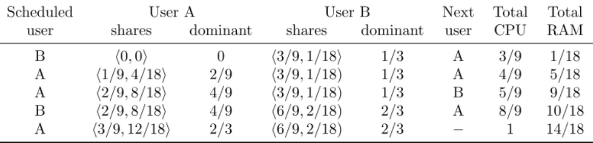
The Dominant Resource Fairness (DRF) scheduling algorithm [4] tracks the total resources allocated to each user as well as the user’s dominant share. At each step, the algorithm selects among the runnable tasks the user with the lowest dominant share. If there are enough resources for satisfying that user’s task, it is launched. An example of DRF allocating resources is given in 1.1. The system considers 9 CPUs and 18 GB RAM to two users A and B running tasks that require h1 CPU, 4 GB RAMi and h3 CPU, 1 GB RAM i, respectively.
The total DRF allocation is given by the solution of an optimization problem, where the vectors hx CPU, 4x GB RAMi and h3y CPU, y GB RAMi are the requirements of users A and B, respectively. Hence, the system intends maximizing allocations max(x, y), while having x + 3y ≤ 9 (CPU), 4x + y ≤ 18 (RAM) and equalizing dominant shares of users A and B, i.e., 4x/18 = 3y/9. Then, users A and B respectively gets h3 CPU, 12 GB RAMi and B h6 CPU, 2 GB RAMi .
Performance results show that DRF leads to better throughput and fairness than the
![Figure 1.1: Virtual and Physical Machine Architectures [1].](https://thumb-eu.123doks.com/thumbv2/123doknet/2325349.30216/23.892.127.712.751.985/figure-virtual-and-physical-machine-architectures.webp)
![Figure 1.9: Microservices involved in a end-to-end IMS service [3].](https://thumb-eu.123doks.com/thumbv2/123doknet/2325349.30216/31.892.197.653.136.424/figure-microservices-involved-end-end-ims-service.webp)
![Figure 1.11: CDF of demand-to-slot ratio in slot-based allocations [4].](https://thumb-eu.123doks.com/thumbv2/123doknet/2325349.30216/38.892.350.600.249.458/figure-cdf-demand-slot-ratio-slot-based-allocations.webp)
![Figure 2.9: Processor-Sharing queue for the modeling of parallelized batch service [6]](https://thumb-eu.123doks.com/thumbv2/123doknet/2325349.30216/56.892.254.712.311.543/figure-processor-sharing-queue-modeling-parallelized-batch-service.webp)