Applications of Plasma Technology in Development of
Superhydrophobic Surfaces: A Review
Reza Jafari
∗Siavash Asadollahi and Masoud Farzaneh
NSERC / Hydro-Quebec / UQAC Industrial Chair on Atmospheric Icing of Power Network Equipment (CIGELE) and Canada Research Chair on Engineering of Power Network Atmospheric Icing (INGIVRE), University of Qu´ebec at Chicoutimi, Chicoutimi, Qu´ebec, Canada
Abstract
Superhydrophobic surfaces, originally inspired by nature, have gained a lot of interest in the past few decades. Superhydrophobicity is a term at-tributed to the low adhesion of water droplets on a surface, leading to water contact angles higher than 150◦. Due to their vast variety of possible applications, ranging from biotechnology and tex-tile industry to power network management and anti-fouling surfaces, many methods have been uti-lized to develop superhydrophobic surfaces. Among these methods, plasma technology has proved to be a very promising approach. Plasma technology takes advantage of highly reactive plasma species to modify the functionality of various substrates. It is one of the most common surface treatment technologies which is widely being used for sur-face activation, cleaning, adhesion improvement, anti-corrosion coatings and biomedical coatings. In this paper, recent advances in the applications of plasma technology in the development of superhy-drophobic surfaces are discussed. At first, a brief introduction to the concept of superhydrophobicity and plasma is presented, then plasma-based tech-niques are divided into three main categories and studied as to their applications in development of superhydrophobic surfaces.
Keywords: Plasma polymerization, etching, sputtering, superhydrophobic surfaces, thin films, nano-structured surfaces
1
Introduction
Wettability of a surface depends on its chem-ical composition and surface micro/nano rough-ness. These two parameters determine the extent
∗reza jafari@uqac.ca, Phone: +1 (418) 545 5011, Fax: +1
(418) 545 5032, 555 Boulevard de l’Universit´e, Chicoutimi (Qu´ebec), Canada, G7H 2B1
of adhesive forces between a liquid droplet and the surface. Superhydrophobicity is where surface roughness meets low surface energy, so the adhe-sion force between water droplet and solid surface significantly decreases [1]. The concept of super-hydrophobicity initially emerged from the investi-gation of natural surfaces with high contact angle and low contact angle hysteresis, notably the lotus leaf (Nelumbo) surface (Figure 1) [2–4].
Figure 1: The photos of some lotus leaves (a) and of a water droplet on a lotus leaf (b) and the SEM images of lotus leaves with different magnifications (c and d). The inset of (d) is a water contact angle on a lotus leaf, with a value of 161◦± 2◦ [5].
Lotus is usually considered as a symbol of pu-rity due to its self-cleaning effect [2, 6]. The superhydrophobic characteristics of the micro-nanostructured and wax-coated surface of the lo-tus leaf was first studied by Dettre and Johnson in 1963 [7]. Since then, several other examples of natural superhydrophobic surfaces have been
dis-covered. The wax nano-crystals on the leaves of Colocasia esculenta (taro leaf) are capable of trap-ping air between a water droplet and the leaf sur-face [8]. Euphorbia myrsinites, another plant na-tive to South-eastern Europe and Asia Minor, has superhydrophobic leaves due to its hierarchically nano-structured leaf surface. Rice leaf, Chinese wa-termelon and India canna leaf are also known to be superhydrophobic [9]. Barthlott et al. studied 350 plant leafs by SEM imaging and showed that the hierarchical roughness on a leaf surface plays an im-portant role in the self-cleaning effect [2]. For more information on natural superhydrophobic surfaces, see [2, 3, 5, 9].
On a self-cleaning surface, water droplets roll-off easily carrying away any contamination, which is why superhydrophobic surfaces are usually consid-ered self-cleaning [3]. During the past few decades, many studies have tried to mimic the natural struc-tures to develop artificial superhydrophobic sur-faces, which can be useful in numerous applica-tions. These applications range from textile in-dustry to power network design and maintenance [10].Several superhydrophobic textiles have been designed to produce water-repellent self-cleaning fabrics [11–13]. In biomedical applications, super-hydrophobic surfaces can be used in vessel replace-ments or wound management [14]. Since icepho-bicity (i.e. low adhesion force between ice and the substrate) shows a correlation with superhy-drophobicity [15], superhydrophobic coatings can be used to reduce the ice accumulation on vari-ous structures, notably power network equipment [1, 4, 16–19]. Construction industry can also bene-fit from the development of superhydrophobic sur-faces for manufacturing self-cleaning windshields and windows [4, 20–22]. In marine industry, super-hydrophobic coatings can be used to develop anti-fouling surfaces for vessel bodies [23]. Finally, due to the minimized liquid/surface contact area, hy-drophobic and superhyhy-drophobic surfaces are able to be utilized as anti-corrosion surfaces [9, 24–26].
Many approaches and techniques can be utilized in order to generate superhydrophobic characteris-tics on various metallic and polymeric substrates. However, all these methods have their own advan-tages and disadvanadvan-tages. Sol-gel reactions [27–29], electrochemical deposition [30–32], layer-by-layer deposition [33–36] and spin coating [37] have been used to fabricate superhydrophobic surfaces. One
of the most promising approaches to the develop-ment of superhydrophobic surfaces is plasma re-lated techniques. Plasma surface treatment is gain-ing popularity in many applications and therefore, many studies have been done on the applications of various plasma-based techniques in generating superhydrophobic surfaces. In plasma processing, plasma parameters have a significant effect on the film properties and characteristics. Hence, to bet-ter design and fabricate a low surface energy coat-ing with a micro/nano structured pattern, which is the defining characteristic of superhydrophobic surfaces, the effects of plasma parameters on the chemistry and morphology of the surface should be fully understood. Each category of plasma process-ing, which will be discussed shortly, contributes to the surface roughness and/or surface chemical com-position. By modifying these properties by plasma processing, it is possible to design fast, economi-cal and practieconomi-cal approaches to develop superhy-drophobic coatings.
In this paper, at first a brief introduction of wet-ting behaviour, superhydrophobicity, plasma and plasma surface treatment will be presented. Then the development of superhydrophobic surfaces by means of plasma surface treatment methods are di-vided into three categories and each category is dis-cussed independently. Finally, a brief conclusion will be presented.
2
Superhydrophobicity
The physical interaction between liquid droplets and solid surfaces has been a point of inter-est for many decades. According to Young, the con-tact angle of a liquid droplet on an ideally flat, rigid and homogeneous surface depends only on the sur-face energy in solid/liquid, solid/air and liquid/air interfaces (Equation 1) (Figure 2) [38]:
cosθc=
γSG− γSL
γLG
(1) In this equation, θc is the liquid contact angle
and γ is the surface energy for which the subscript denotes the relative interface. As mentioned be-fore, the above equation is only valid for ideally flat surfaces. It has been proven that by modifying the surface chemical composition of a flat surface, and thus reducing the surface energy, the maximum contact angle achievable is 120◦ [39]. However, the wettability behaviour of a surface depends on two
Figure 2: A liquid droplet on an ideal surface. The contact angles on both sides are equal (Young model)
factors: (i) surface energy and (ii) surface rough-ness [40]. To precisely predict the contact angle on a roughened surface, the effect of roughness on the solid/liquid interface should be taken into account. Many studies have tried to formulate a relation-ship between surface chemical energy, roughness and contact angle. However, two main models exist which are generally accepted throughout different studies: (a) Wenzel model and (b) Cassie-Baxter model. The Wenzel model predicts that the water penetrates the holes on the surface and therefore the contact area between water and solid surface increases with roughness. The surface condition for which the penetration occurs is called the Wen-zel regime (Figure 3a). WenWen-zel predicts that the contact angle on a rough surface can be calculated through the Wenzel equation (Equation 2 ) [41]:
cosθW = rscosθc (2)
In the above equation, θc is the equilibrium
con-tact angle, θW is the Wenzel contact angle and rs
is the surface roughness. It is clear that according to Wenzel, roughness will cause the contact angle to increase only if the contact angle is higher than 90◦. In other words, roughness in Wenzel regime in-creases the hydrophobicity in an already hydropho-bic surface and increases the hydrophilicity in an already hydrophilic surface [9, 42].
However in many cases, due to an increased height-to-area aspect ratio in the roughness, liq-uid phase cannot penetrate the roughness cavities. In this state, air is trapped between the liquid and the solid and therefore a mixed-phase interface is formed [43]. The second model deals with the lat-ter state and is called the Cassie-Baxlat-ter model. A mixed phase interface will increase the contact an-gle, regardless of the surface energy [9]. The
Cassie-Baxter model predicts the relationship between the surface roughness and contact angle through the Cassie-Baxter equation (Equation 3) [44]:
cosθCB = fscosθc− (1 − fs) (3)
In the above equation, θc is the equilibrium
con-tact angle, θCB is the Cassie-Baxter contact angle
and fs is the fraction of the solid in contact with
the liquid (Figure 3b).
Several studies were performed in order to iden-tify the transition point between Wenzel and Cassie-Baxter regimes regarding the roughness di-mensions. Theoretically, it has been shown that the dominant regime is always the one with the smaller contact angle [22,45]. In other words, contact angle can be completely translated to Gibbs free energy. Patankar et al. showed that for some roughness geometries, an energy barrier has to be overcame for the transition to occur [46]. They further ar-gued that the decrease in the gravitational poten-tial energy, resulted from the gradual penetration of water into the surface gaps, can help to overcome this barrier. Xia et al. showed that the spacing be-tween the roughness features (b) can determine the dominant wetting regime [45]. They used plasma etching with a photoresistive mask to fabricate 12 samples with different spacings, ranging from 5 to 60 µm.
Figure 3: (a) Wenzel regime, liquid penetration in the roughness cavities is visible, (b) Cassie-Baxter regime, air is trapped between the liquid and the surface, forming a composite interface and thus re-ducing the adhesion forces and (c) Mixed regime, where the partial penetration of water occurs.
On the other hand, it has been showed that the dominant wetting regime is also depended on the size of the droplet used in contact angle mea-surement [45, 47]. Brown et al. studied the droplet behaviour upon impact on fluorinated su-perhydrophobic surafces with different roughness scales from nano to micro structure [47]. They ar-gued that for a droplet in microlitre size, the
liq-uid/substrate contact area is extremely larger than the surface features, and therefore the droplet im-pact behaviour is less affected by surface charac-teristics. When the size of the droplet decreases to the range of picolitres, contact area is only one or-der of magnitude larger than surface asperities, and therefore picolitre droplets exhibit completely dif-ferent behavior on nano-roughness than on micro-roughness structures.
Finally, it should be noted that the Cassie-Baxter regime is a quasi-stable state and tends to gradu-ally transform into Wenzel regime. However, the mechanism responsible for the penetration of liq-uid into the surface texture and therefore transi-tion between two regimes is not yet fully under-stood [48, 49].
Complete Wenzel or Cassie-Baxter regime is rare in occurrence, and usually a mixed state is observed where water partially penetrates the holes in the roughness (Figure 3c) [50].
As mentioned before, the above equations can generally be utilized in various applications. How-ever, some studies have cast doubts on the gener-ality of Wenzel and Cassie-Baxter equations. It is proven that these models are only true when the drop size is infinitely bigger than the roughness sizes. Very small drops will become axisymmet-ric, even if the surface shows no sign of symmetry whatsoever [51]. Marmur et al. added an extra cri-terion for transition to the Cassie-Baxter regime in relation to Gibbs free energy. They indicated that even if the Cassie-Baxter equation is satisfied with-out this extra criterion, Wenzel regime will be dom-inant [22]. Brandon et al. also demonstrated that two dimensional models, like Wenzel and Cassie-Baxter, are not truly accurate. They proposed a simulation-based method, which is claimed to be more accurate than the current models [52]. How-ever, most studies on hydrophobic surfaces assume that these models are accurate enough to estimate the surface wettability behaviour.
Besides static contact angle considerations, con-tact angle hysteresis (CAH) is another important criterion in studying the surface behaviour of var-ious materials. Contact angle hysteresis is defined with regards to dynamic contact angles, i.e. contact angles related to moving liquid fronts (interfaces). For instance, when a droplet is moving on a sur-face, the contact angle in the movement direction is called the advancing contact angle and the
con-tact angle on the other side of the droplet is called the receding contact angle.
It is notable that some studies suggest that the concept of static contact angle should be reconsid-ered [53–57]. It is argued that every so-called static contact angle is in fact an advancing contact an-gle, and it should be treated as such. Others have claimed that although measurement of static con-tact angle is not easy, but by giving the droplet enough time to reach the state of global minimum energy, in some cases it is possible to observe the ’equilibrium’ droplet [58]. Either way, most studies reviewed in this paper refer to the contact angle measured for a drop at rest on a surface as static, stationary or equilibrium contact angle.
Contact angle hysteresis is defined as the differ-ence between two dynamic contact angles [43]. It is known that the droplets in Cassie-Baxter regime tend to have smaller contact angle hysteresis com-pared to droplets in Wenzel regime [43].
Contact angle hysteresis is an important factor in roll-off behaviour. Lower contact angle hystere-sis usually means lower adhesion force between the droplet and the surface and easier sliding of the droplet on the surface [1]. Easy sliding of a liquid droplet on the surface has been proven to be an essential factor in many applications, notably self-cleaning surfaces and anti-icing applications [3]. In the roll-off phenomena, droplets will roll off the surface easily, absorbing dirt and external parti-cles [59]. It has been even suggested that in order to accurately demonstrate the wettability behaviour, measuring the dynamic contact angles is essential. It has been argued that contact angle hysteresis is a significant tool to fully realize the surface topog-raphy and that instead of maximum contact angle achievable, CAH should be taken into account [60]. Generally, superhydrophobic surfaces are defined as any surface for which the water contact angle (WCA) is more than 150◦ [39, 61–63]. However, some studies add the criteria of low sliding angle or contact angle hysteresis to the definition [10, 14].
As mentioned before, two factors contribute to the superhydrophobicity of a surface: (i) surface roughness and (ii) surface chemical composition. Thus there are two approaches to generate the face structures leading to superhydrophobic sur-faces: (i) roughening an already low surface energy material or (ii) roughening a surface and then treat-ing it with low surface energy coattreat-ings [14].
Poten-tially, plasma processing is an ideal technique for both approaches. It can be relatively fast, econom-ical and easily controlled, which makes it a suit-able choice for industrial processes. One notsuit-able advantage is the fact that it can be used to change the surface chemistry while increasing the rough-ness, which makes it possible to fabricate superhy-drophobic surfaces in a one-step processes. There-fore, it can be indicated that superhydrophobic sur-faces can be developed by carefully controlling the plasma process and studying the effects of plasma parameters on surface characteristics. During the past few decades, many studies have been done in-volving both approaches which use plasma process-ing techniques for inducprocess-ing roughness on a surface and/or deposition of low surface energy coatings.
3
Plasma
Technology
and
Plasma Treatment
Generally, plasma is an ionized gas which can be considered as the fourth state of matter. It con-stitutes more than 99% of the universe. Macro-scopically, plasma is electrically neutral. However it contains free charge carriers and is electrically conductive. To generate plasma, enough energy must be applied to a gas. This energy is usually provided by an electric source, which can be direct current (DC), radio frequency (RF), low frequency (LF) or microwave frequency (MW) [64, 65].
Plasma technology is an emerging field with as-tonishing potential applications. Thousands of re-search papers are published every year on plasma technology, revealing the vast possibilities offered by this relatively new field. In medicine, plasma treatment can be used for wound management, tumour treatment, tissue engineering, equipment sterilization and surgery equipment [66, 67]. By means of functionalization (i.e. grafting of the new functional groups on the treated surface, see 4.2), plasma technology also is being utilized to im-prove polymer surface properties by applying reac-tive gases plasmas (like O2, N2, N H3 and H2O)
to the polymer surface [68]. It is also being used in electronics industry in a wide range of applica-tions, from adhesion promotion and cleaning to fab-rication of semiconductors [69]. Plasma reactions can also be used for plastic and nuclear waste dis-posal [70] and nitriding or carburizing of steels [71]. Plasma can exist at various gas pressures. The
gas pressure defines the LTEs (local thermody-namic equilibriums at the plasma) [65], and there-fore can significantly affect the nature of the plasma. Low pressure plasma technology is widely industrialized and it is used in many applications, such as neon lamps and plasma screen TVs [64]. Other applications include deposition of metal-lic coatings with minimum impurity and metal matrix composite coatings [72]. However, low-pressure plasma imposes several technical diffi-culties, mainly related to the vacuum equipment [64]. To address these issues, another category of plasma has been introduced, which operates at at-mospheric pressure. Atat-mospheric pressure plasma can be used for several applications, like surface modification, without the adversities induced by low pressures. Atmospheric pressure plasma re-actors requires less energy and offers shorter pro-cess times compared to low-pressure plasma [64]. However, atmospheric pressure plasmas are usually harder to control because an unknown amount of air mixed with carrier and reactive gases. Further-more, complex interactions can affect the efficiency of the treatment and hence the quality of the de-posited layer [73].
As mentioned before, for the development of su-perhydrophobic surfaces, induction of the two char-acteristics, low-surface energy chemistry and mor-phological roughness, is essential. Plasma technol-ogy for enhancement of superhydrophobic charac-teristics is of great interest, because plasma pro-cessing can be used in generation of both char-acteristics. This technology can be used to de-posit coatings (by means of plasma polymerization or plasma sputtering), increase the roughness (by means of plasma etching) and increase the amount of hydrophobic functions on the surface (by means of functionalization). In this paper, plasma sur-face modification is divided into three categories: (1) plasma etching, (2) plasma polymerization and (3) plasma sputtering. Plasma etching is mainly used to generate roughness on the surface, though it may change surface chemistry to some extent. On the other hand, plasma polymerization and plasma sputtering are generally used to develop thin films from low surface energy materials, but they may also increase surface roughness.
4
Plasma Etching
As mentioned before, roughness is an essen-tial characteristic of superhydrophobic surfaces. Plasma etching is the process of selective removal of materials from a surface by reactive plasma rad-icals. Certain plasma particles react with cer-tain atoms [74] or cercer-tain phases [61] on the face and reaction products are ejected off the sur-face as gaseous compounds. For example, oxygen plasma is mainly used in etching of organic mate-rials, where oxygen reacts with carbon and hydro-gen and produces gaseous carbon dioxide, carbon monoxide and water [74].
Generally, in etching processes, a photo-resistant mask can be used to protect parts of the surface from exposure to the etching medium [74]. In con-ventional or wet etching methods, various chemi-cal reactions are utilized to selectively remove the materials exposed to the solvent. However, wet etching has many disadvantages compared to the plasma etching approaches. Unlike plasma etch-ing, wet etching techniques can be problematic for small film thickness, and they can also pose some environmental threats [65, 74]. Plasma etching on the other hand, is a dry and precise technique with-out the serious limitations of conventional etching methods [74].
Plasma etching is based on selective erosion, rather than homogeneous erosion which leads to significantly lower roughness. Usually one phase or compound reacts more readily with plasma gas and therefore, etching rate is different at various locations on the surface [74]. It has been suggested that other nano structures can be used as an equiv-alent to the photo-resist mask in order to further enhance the roughness. For example, polystyrene (PS) beads have been deposited by different chem-ical techniques on glass substrates [75, 76]. Oxygen erodes one phase more readily, in this case the glass layer on the bottom, therefore an increase in rough-ness can be observed compared to the case without the PS layer.
A wide variety of gases can be used in plasma etching technique. However, some gases, like O2,
Ar and CF4 have proven to be more suitable in
development of micro-nano structured roughness on various substrates. In development of super-hydrophobic surfaces, CF4 is of specific interest,
since it has been shown that plasma etching with
CF4can simultaneously fluoridate and roughen the
surface. [77–79].
Generally, etching is used to induce nano/micro sized roughness on various substrates to generate superhydrophobicity. However, there are two ap-proaches available for different materials. Etching can be used as pretreatment before coating the sur-face with low sursur-face energy material [21, 61, 62, 80] or it can be used to generate roughness on a low surface energy material [59, 81].
4.1
Etching as a Pretreatment
Pro-cess
The most common application of plasma etch-ing in development of superhydrophobic surfaces is to generate a micro/nano scale roughness on the surface. As mentioned before, this rough-ness along with a chemical modification can en-hance the surface’s hydrophobic characteristics. In other words, two subsequent stages are performed (etching and coating) to induce two general char-acteristics of a superhydrophobic surface (rough-ness and low surface energy, respectively). Several studies utilized plasma etching to induce rough-ness on a substrate prior to subsequent coating with low surface energy materials, e.g. fluorocar-bons and organosilicons. It can be expected that plasma etching as a pretreatment can result in sig-nificantly higher contact angles. The most common gas used in plasma pretreatment of organic mate-rials is oxygen. Substrates such as polycarbonate, poly(ethylene tetraphalate), cellulose paper, poly-polyurethane and poly(propylene) have been used with oxygen plasma pretreatment. Other studies have investigated the effects of fluorocarbonic gases (e.g. CF4 and SF6) in plasma pretreatment on a
different class of substrates, such as polished sil-icon and glass, but the deposition of fluorocarbon groups along with etching cannot be overlooked and therefore the process is a mixture of etching and functionalization. This phenomena will be further discussed in section 4.2. In order to better con-trol the process, the effect of plasma parameters on the morphology, chemical composition and wetting behaviour of the surface must be fully understood. Many studies have investigated such correlations, about which a review is presented in this section. Effect of Plasma Power and Treatment Time It has been shown that increasing the plasma power and treatment time in plasma etching can improve
the hydrophobic behaviour up to a point, but a critical power [21, 82] and a critical treatment time [21, 80, 82, 83] exists beyond which superhydropho-bicity diminishes. This threshold denotes the point where roughness units (the units consisting the roughened structure, which are named variously, such as nano fibrils, nano columns, etc.) become unstable and tend to collapse and/or agglomerate to form larger units. Larger roughness units may decrease the overall roughness (Figure 4), hence decrease the superhydrophobic characteristics. On the other hand, based on drop impact experiments, it has been suggested that larger units can also in-crease the mechanical stability of the coatings [83]. However, performing more mechanical tests seems to be necessary in order to reach a final conclusion.
Figure 4: SEM images of the PET surfaces treated with oxygen plasma at various powers: (a) un-treated, (b) 50 W, (c) 100 W and (d) 200 W. Treat-ment time is 10 minutes for all samples [84].
Effect of Gas Pressure Gas pressure also has a significant effect on oxygen plasma etching. It has been argued that by increasing the pressure, the collisions between plasma particles increases, so that less particles with enough energy will be able to reach the surface, resulting in reduced roughness [82].
4.2
Etching as a Treatment Process
Etching can be used as an stand-alone treat-ment to develop roughness on low-surface-energy materials and therefore to generate superhydropho-bic coatings. Several studies have investigated
the effect of plasma etching on the generation of micro/nano structured roughness on various hy-drophobic materials, specifically PTFE [77, 85–87]. In the case of PTFE, oxygen has proven to be sig-nificantly useful to enhance the hydrophobicity of PTFE substrates. It has been shown that oxy-gen uptake on the PTFE surfafce is almost non-existent even after 3 hours of plasma treatment, and thus the amount of polar oxide hydrophilic groups deposited by oxygen plasma etching is neg-ligible [77, 86, 87].
Many parameters can affect the roughness and morphology on the surface. In this section, a review of such studies is presented.
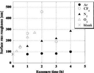
Effect of Plasma Gas Plasma gas used in a plasma etching process can significantly affect the wetting behaviour [77]. One of the most efficient gases is oxygen. Other common plasma gases, like argon or nitrogen, have proved to be ineffective at best in etching of PTFE [85,87]. In case of nitrogen gas, the deposition of nitrogen groups on the sur-face will even increase the sursur-face energy [87]. How-ever, adding oxygen to the mixture was shown to increase roughness, and thus increase hydrophobic-ity (Figure 5) [85]. The amount of oxygen grafting also appears to be minimal in the case of oxygen plasma etching [87], so that no undesired oxygen grafting is observed.
Figure 5: The effect of O2flux in Ar/O2mixture on
contact angle of PTFE. Increasing the O2 flux will
enhance the hydrophobic behaviour of PTFE [85].
Effect of Plasma Power Plasma power is an-other parameter to be considered. Low plasma powers results in the sole activation of the sur-face, and therefore have proved to be ineffective
in plasma etching [86]. Increasing the power usu-ally leads to higher amounts of erosion, which will subsequently increase the roughness (Figure 6) [81, 86, 88, 89]. However some results are in-consistent as concerns coating chemical composi-tion. Some studies suggest that coating chemical composition only depends on the composition of the etching gas, and that both treatment time and plasma power are irrelevant as to the coating com-position [81].
Figure 6: Advancing (θa) and receding (θr) WCA
values of the PS samples treated with a CF4/O2fed
discharge with 17% O2 as a function of treatment
time at (a) 150W and (b) 300W [81].
Functionalization Besides the plasma etching technique on low surface energy materials, some plasma gases, mainly CF4 can be used for
simul-taneous etching and fluorination of the surface. In this case, fluorinated groups deposited on the surface can further decrease the surface energy. Chemically modifying the surface by some func-tions with a specific application is called
function-alization [90, 91]. Technically, it is different from polymerization in the fact that it involves cova-lently binding plasma species to the surface, rather than coating a surface [92]. CF4 is considered an
etching gas and it does not readily polymerize on the surface [76, 80, 81]. However, samples etched with CF4exhibit a significant amount of
fluorocar-bonic groups along with high roughness [77, 89, 93]. It was also shown that fluorinated samples can be cross-linked by UV exoposure or annealing [93, 94]. Cross-linked samples exhibit improved mechanical durability without any significant change in surface morphology. In the case of UV exposure, it was shown that by using a photolithographic mask, the exposed areas will be of lower height and therefore form a micro-pattern which in turn can further in-crease the water contact angle [94].
Due to the simultaneous roughening and func-tionalizing effect of CF4, it has proved to be more
efficient in developing superhydrophobic surfaces than SF6, Ar, N2 and O2[77–79]. Its advantage is
not always due to the higher extent of roughness, but rather to the resulting lower surface energies. In fact, it has been shown that O2 will generate
slightly higher roughness on the PTFE samples in the same time (Figure 7), but lower contact angles will be achieved due to the lack of fluorine function-alization [77]. Many studies have also investigated the effect of adding CF4 to oxygen or other
com-mon plasma gases [12, 79, 81]. For example, it has been shown that for polystyrene samples, 17% of oxygen will result in the highest extent of fluorina-tion and texturing [81]. Although this paper, like several other studies, consider CF4 as an etching
agent, it should be noted that it can cause more effects than just erosion.
5
Plasma Polymerization
Plasma treatment can be utilized to deposit thin films on various substrates. The process, which is usually called plasma polymerization, is referred to the deposition of polymer films through dissociation and excitation of a monomer gas in plasma and subsequent deposition and polymeriza-tion of the excited species on the surface of a sub-strate [65]. In comparison to conventional surface treatment methods, plasma polymerization can be a very advantageous approach. Indeed, it is capable of forming ultra-thin films with suitable mechani-cal properties [95, 96], it requires lower
tempera-Figure 7: Effect of etching gas on contact angle. Note that etching time for oxygen is 1.5 hours and for other gases is 4 hours [77]. The highest contact angle is achieved for CF4after 2 hours of exposure,
which can be explained by simultaneous etching and fluorination of PTFE substrate. The rough-ness measurement is performed by atomic force mi-croscopy.
tures [65], can be used for monomers that do not polymerize under normal conditions [97, 98] and is environmentally friendly [12, 95].
As mentioned before in Section 3, plasma poly-merization can be divided into two general cate-gories: (1) low pressure (pressures less than at-mospheric pressure) and (2) atat-mospheric pressure. Low pressure plasma polymerization tends to gen-erate more homogeneous films with less impuri-ties. It is also considered to be a green process due to significantly less amount of process gases in-volved [99]. On the other hand, atmospheric pres-sure plasma polymerization can be advantageous due to its lower energy consumption, shorter pro-cessing times, lack of need for vacuum equipment and considerably higher growth rates [100–102].
Pulsed plasmas or modulated glow discharges are used frequently in plasma polymerization applica-tions. In a modulated glow discharge, plasma is turned on for a small fraction of the total cycle ttotal. In the tof f period, enough time is given
for the polymerization process. The ratio between ton/ttotal is called duty cycle, and is often
abbrevi-ated as DC. It has been shown that a pulsed plasma can lead to unique morphologies or enhance the
su-perhydrophobic behaviour [62, 103, 104]. For ex-ample, in plasma polymerization of 1H,1H,2H,2H-perfluorooctyl acrylate (PFAC), deposited layers in pulsed and continuous deposition are very simi-lar in chemical composition. However, morphol-ogy is significantly different, leading to much higher WCA and much lower CAH values in the case of pulsed plasma polymerization (Table 1). More-over, in pulsed plasma polymerization, duty cycle should be considered as an extra control parameter which can significantly affect the surface character-istics [62, 104].
Several materials can be used in plasma polymer-ization, such as oxides, nitrides, and oxynitrides of silicon, crystalline materials such as polycrystalline silicon, epitaxial silicon, and refractory metals and their silicides. These materials play a crucial role in development of microelectronics [105]. However, in superhydrophobic applications, it is essential to consider materials with low surface energy. For im-provement of hydrophobic behaviour, some specific materials are suitable due to their low surface en-ergy, such as fluorocarbons and organosilicons [14]. But it should be noted that not all the materi-als in the mentioned categories can be utilized in plasma polymerization. Several studies have been carried out on the development of superhydropho-bic fluorocarbonic surfaces which are discussed in Section 5.1. Organosilicon-based superhydrophobic surfaces are also discussed in Section 5.2. Further-more, a few studies have investigated the develop-ment of plasma polymerized superhydrophobic sur-faces with other precursors, such as T iCl4, CH4or
acetylene. These studies are reviewed in Section 5.3.
5.1
Fluorocarbonic Monomers
Fluorocarbon polymers are well known for their low surface energy attributed to CF2and CF3
groups. Hare et al. showed that the surface energy of hydro/fluoro carbon groups decreases in the fol-lowing manner [106]:
−CH2> −CH3> −CF2> −CF3
It has also been shown that increased fluorine content in a plasma polymerized coating leads to higher contact angles [107]. Thus, fluorocarbons are among the most common choices for develop-ment of superhydrophobic surfaces [108].
Generally a fluorocarbon-based coating consists of CFx groups. For depositing CFx groups on a
Table 1: Comparison between pulsed plasma polymerization and continuous plasma polymerization 1H,1H,2H,2H-perfluorooctyl acrylate as precursor. Significant improvement in contact angle and contact angle hysteresis is observed [103].
deposition mode off time advancing receding Pulsed (5 × 1 min) 2 min 168◦± 0.8◦ 165◦± 1.2◦
Continuous (1 × 5 min) - 145◦± 1.2◦ 47◦± 1.5◦
surface, C2F4or C4F8gases are usually used as the
plasma gas. CF4is another fluorocarbon gas which
is usually used along with O2for etching purposes,
However it can lead to simultaneous functionaliza-tion with CFx groups which in turn can enhance
superhydrophobicity (see section 4.2).
PTFE (polytetrafluoroethylene) is a fluropoly-mer which is also known comfluropoly-mercially as TeflonTM.
It has been widely used as a hydrophobic and low friction surface. However, due to its solid state in room temperature, PTFE is not generally consid-ered as an appropriate choice for plasma polymer-ization. Therefore, PTFE coatings are often gen-erated by sputtering or other suitable techniques. However, some efforts have been made by 2applica-tion of high evapora2applica-tion temperatures [109] or us-ing tetrafluoroethylene (TFE) as a precursor [62] to achieve plasma polymerized coatings close to PTFE. In fact, thin films achieved by these meth-ods usually show a great resemblance to PTFE as to chemical composition.
Effect of Plasma Power As mentioned before, plasma polymerization is based on disintegration of plasma species and polymerization on the surface. It is clear that in higher plasma powers, the extent of energy applied on the plasma gas is increased, and therefore higher amounts of molecular frag-mentation can be expected. Therefore, in studies reviewed in this paper, the amount of CFx species
decreases as the power increases [80,110,111]. How-ever, since plasma power can also affect the surface roughness to some extent, this does not necessarily mean that by increasing the power, hydrophobicity diminishes. In fact, some studies report an increase in contact angle due to increasing roughness with increasing the plasma power, although the amount of hydrophobic organic groups on the surface de-creases [110].
Effect of Monomer Partial Pressure Monomer pressure can have a significant
ef-fect on the film composition too. This correlation is mainly due to the lower monomer fragmentation at higher pressures [112].
Effect of Deposition Time Treatment time is another effective parameter which has to be con-sidered. It has been suggested that treatment time will only increase the film thickness. Thus after a point where complete coverage occurs, treatment time should not have any effect on wetting be-haviour [113]. However, another study shows that film composition is also dependent on the treat-ment time. It was shown that for longer treattreat-ment times, the amount of fluorocarbon groups increases on the surface [114].
5.2
Organosilicon Monomers
Besides the significantly low surface energy in fluropolymers, some disadvantages, mainly of en-vironmental nature, can limit the potential appli-cations of such precursors [115, 116]. Due to these issues, other precursors have been considered for superhydrophobic applications. Although the sur-face energy of CH3and CH2 groups, to which the
hydrophobicity of organosilicons is attributed, is not as low as that of fluorine-based groups [117], organosilicon based polymers are considered as an environmentally friendly alternative to fluorine-based polymers for hydrophobicity applications [118]. Organosilicon monomers can be a gener-ally suitable choice for further studies due to their usual liquid state, volatility, safe handling, avail-ability and low cost [119]. As a polymerized coat-ing, they also show good optical and mechanical properties [97]. Some studies have even reported an increase in roughness after polymerization with organosilicons (Figure 8) [84]. Various precursors can be used as monomer in plasma polymerization of silicon-based coatings [14, 40, 100, 102, 118–122]. However, the most promising results have emerged from an organosilicon called Hexamethyldisiloxane (O[Si(CH3)3]2, abbreviated as HMDSO).
Figure 8: AFM images of PET samples (a) before plasma polymerization (after oxygen plasma etch-ing) and (b) after the deposition of TMS [84].
Effect of Oxygen Presence The chemical com-position of plasma polymerized organosilicon based thin films is greatly affected by the percentage of oxygen in the feed gas. Several studies have shown that to preserve the amount of hydropho-bic organic groups (i.e. Si − C bonds) on the sur-face, oxygen percentage should be as low as possi-ble [21,123,124]. The presence of oxygen in the feed gas results in abundance of polar and hydrophilic SiOx groups on the surface, which can render the
surface more hydrophilic. Furthermore, oxygen in the plasma can react with the deposited carbon and decrease the amount of organic groups [123]. In other words, organosilicon based monomers and specifically HMDSO are suitable choices for the de-position of superhydrophobic coatings only if the percentage of oxygen in the plasma is carefully con-trolled.
Effect of Monomer Ratio to Overall Feed Gas The amount of organosilicon-based monomer is of great importance in plasma polymer-ization. It has been suggested that up to a critical amount, a higher percentage of monomer in the feed gas will lead to higher contact angles [125]. This can be due to an increase of organic groups
in the plasma with increasing monomer percent-age [126]. In this case however, plasma power plays an important role. It was argued that a critical monomer percentage exists, below which the in-fluence of concentration is dominant on the sur-face morphology and chemical composition [126]. If the concentration is increased above this amount, plasma power will become the controlling parame-ter.
Effect of Plasma Power The effect of plasma power in the plasma polymerization of organosil-icons is rather similar to that of fluorocarbons. Higher plasma power will increase the degree of fragmentation in the plasma gas and therefore less organic groups will be deposited on the surface [126, 127].
Effect of Deposition Time Treatment time can have a significant influence on the chemical compo-sition of plasma polymerized film. It was shown that the amount of Si − (CH3)2on the surface
in-creases with longer treatment times, thus the sur-face energy is reduced and superhydrophobic be-haviour is enhanced [118].
5.3
Other Precursors
Although studies on plasma polymerization for superhydrophobic surfaces are mainly focused on the fluorocarbons or organosilicons, some works have considered the use of other precursors to gen-erate water repellent surfaces. These precursors can be used with more conventional precursors as improving agents, or they can be used as the sole precursor.
HMDSO is an ideal precursor for superhydropho-bicity applications for several reasons. How-ever, compared to more conventional fluorocarbons, higher surface energy of HMDSO results in weaker wetting properties. Several studies have been done to address such issues. Toluene was investigated as an improving agent for organosilicon based coat-ings [122, 128]. Different Toluene/HMDSO ratios have been studied and in one study, the optimized percentage of Toluene in HMDSO was determined to be 25% [128].
Hydrocarbon groups, and specially methyl groups, are responsible for the superhydrophobic behaviour of some coatings. Hence, one might expect that hydrocarbon gases themselves can be used in plasma polymerization processes to de-velop hydrophobic and superhydrophobic surfaces.
Indeed, several hydrocarbon gases, like methane [129–131], acetylene [132, 133] and propane [133], have been used to develop hydrophobic thin films. Some studies have investigated the addition of flu-orocarbons [130, 133], and as it can be expected fluorine-based groups deposited on the surface can enhance the hydrophobic behaviour even further.
The effect of plasma parameters on the prop-erties of polymerized films is similar to the case of organosilicons and fluorocarbons [132], Except in the case of hydrocarbons, saturation is easily reached, which means that increasing the pressure improves the superhydrophobic characteristics up to a point [132]. Beyond that threshold, no signifi-cant change can be observed as to hydrophobicity. At this stage, and exceptional point should be made for the case of T iO2. The development of
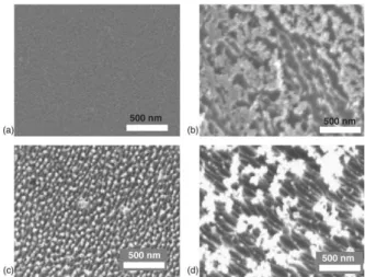
superhydrophobic T iO2surfaces with atmospheric
pressure plasma jet has been reported [134]. A mixture of oxygen, T iCl4 and argon as carrier gas
was used to generate a unique structure of titanium dioxide on the surface (Figure 9).
Figure 9: SEM image of T iO2 nano-crystals
de-veloped by atmospheric pressure plasma jet. SEM images are shown in various magnifications [134]
Generally metallic oxides are considered to be of high surface energy and thus hydrophilic. Sev-eral studies have reported the generation of su-perhydrophobic surfaces based on titanium diox-ide [29, 135–137]. This phenomena is usually at-tributed to the physical structure of titanium diox-ide, which can be altered by changing the manufac-turing process and/or UV light exposure [136, 137]. Similar studies have been done on ZnO based
su-perhydrophobic surfaces and it was shown that the high degree of roughness generated by the deposi-tion of metallic nano-structures on the surface can lead to a superhydrophobic surface, regardless of the surface chemistry [138–140].
6
Sputtering
Sputtering is another method for plasma sur-face treatment. In plasma sputtering, the coating material (target) and substrate are placed as cath-ode and ancath-ode in a plasma reactor, respectively. A feed gas (e.g. argon) is injected between the electrodes and a voltage in the range of 100 V to several kV is applied [71]. Positively charged ions from the plasma strike negatively charged parti-cles with high energy, thus disintegrating atoms or molecules from the cathode surface. Ejected atoms then settle on the surface of the substrate, forming a thin film from the target material [71]. Compared to conventional coating techniques, sputtering is a simple, environmentally friendly and time saving process which results in more adhesive films [141]. It is also not limited by the melting point of the coating materials [71] and is capable of forming multicomponent thin films (e.g. alloys) on various substrate [74].
Few studies have been done on the development of one-step methods for fabricating superhydropho-bic surfaces. However, it should be noted that some studies have investigated the effect of pre-roughening of samples in plasma sputtering pro-cess. For example, bohemitage or anodization of aluminium samples results in micro-nano roughness on the surface [18, 39]. Just like polymerization, pre-roughening of the samples have been proven to be an efficient approach in the development of su-perhydrophobic surfaces.
6.1
Sputtering of PTFE and other
fluorocarbon-based materials
Polytetrafluoroethylene (PTFE) is one of the most common materials in sputtering technology. Many studies have been done on the deposition of PTFE on various substrates by plasma sputtering. In the case of PTFE, plasma sputtering is of signif-icant interest because tetrafluoroethylene does not exhibit some essential properties required in other deposition methods. It does not dissolve readily in any solvent and its vaporization temperature is more than 400◦C [39]. Therefore sputtering is one of the few methods available for the
develop-ment of PTFE thin films. Furthermore, it has been proved that compared to plasma functionalization by CF4 and H2, sputtering of PTFE will cause an
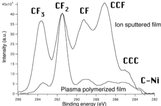
increased deposition of some hydrophobic groups, like CF3 and CF (Figure 10) [142]. It should be
noted that this study [142] refers to the deposition of CF2groups by means of CF4/H2glow discharge
as ’polymerization’, but the film thickness is re-ported to be about 5 nm, which indicates that the process occurring is rather functionalization than plasma polymerization.
Figure 10: A comparison of the two as-deposited XPS results for functionalization and sputtering of PTFE-like thin films. The XPS spectra are nor-malized to the CF2peak. The higher CF2content
of the plasma polymerized film indicates the pres-ence of long linear chains, similar to that of pure PTFE. Sputtering tends to deposit a more chemi-cally heterogeneous film [142].
Effect of Sputtering Gas Several studies have investigated the effect of different sputtering gases on surface composition and morphology. Argon is the most common gas used in plasma sputter-ing [143–146]. Other inert gases like neon and he-lium can be utilized to minimize the deposition of undesired groups on the surface [143, 145]. It was shown that in the case of inert gases, the content of fluorine increases as the atomic mass of the in-ert gas increases [145]. Using nitrogen was shown to lead to the deposition of nitrogen-based groups, like C − N − F and C − N [144]. Interestingly, us-ing hydrogen in plasma sputterus-ing does not result in any deposition whatsoever [145].
Effect of Pressure It has been discussed that increasing the pressure of plasma gas will lead to higher roughness and an increased deposition of −CF2 groups [146–148]. The significant effect of
pressure on sample roughness can be used to design unique processes to improve the superhydrophobic behaviour of various surfaces. For example, using two different pressures subsequently, two different levels of roughness were achieved [28], resulting in a hierarchical structure which is a well-known reason for superhydrophobicity in many natural examples (see Section 1). However, increasing pressure can decrease the mean energy of ions, and subsequently reduce the growth rate [148].
Effect of Target-Substrate Distance It was shown that the influence of target-substrate dis-tance on superhydrophobic behaviour is dependent on gas pressure. At higher pressures, increasing the target-substrate distance can increase the sur-face roughness, while at lower pressures, target-substrate distance does not have a significant effect on wetting characteristics [146].
6.2
Other Sputtering Targets
Although conventionally PTFE was used in many sputtering studies, few studies have been done on other materials as sputtering target [42, 149].
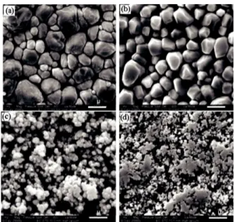
In this case, the basics of plasma sputtering are generally similar to the processes mentioned before. However some details may be changed according to specific cases. For example, in case of copper, plasma power was shown to alter the film purity and roughness size (Figure 11). Therefore it was suggested that higher plasma powers should be uti-lized to decrease the extent of Cu2O and obtain a
purer copper coating, as well as to achieve a suit-able roughness scale [149].
Finally, a point should be made on one spe-cific study with a two-step method to generate hybrid superhydrophobic surfaces. A structure of cadmium/cadmium oxide was generated by plasma sputtering of cadmium and subsequent thermal ox-idation [42]. Significantly high roughness observed in these samples (Rrms= 50 nm) is thought to be
responsible for their highly superhydrophobic be-haviour.
Figure 11: SEM images of films deposited by cop-per sputtering for (a) 400 W, (b) 300 W, (c) 200 W and (d) 100 W. The reduction in copper nano crystals dimensions is observed [149].
7
Conclusion
Superhydrophobic surfaces, once inspired by nature, are gaining a lot of interest due to their extensive range of possible applications. These po-tential applications, ranging from biotechnology to construction, and from power network maintenance to textile industry, motivate many researchers to investigate various approaches and techniques to develop superhydrophobic surfaces. Among theses, plasma based techniques seem to be very promis-ing. By carefully optimizing and adjusting the process parameters, plasma surface treatment can be an environmentally friendly, cheap, easy and fast method to develop cross-linked and mechani-cally stable superhydrophobic surfaces. During the past few years, many studies have been carried out on the development of superhydrophobic surfaces using plasma etching, plasma polymerization and plasma sputtering. Understanding the effective pa-rameters involved with plasma treatment can lead to a better control on the surface morphology and chemistry. Many studies have aimed at optimiz-ing these parameters in order to develop easier and cheaper methods to produce superhydrophobic sur-faces with better quality and stability. These
re-cent rapid progresses in both plasma technology and surface engineering offer a promising future for this new and advancing field of science.
References
[1] Shirtcliffe, N. J., McHale, G., and I. Newton, M. June 2011 J. Polym. Sci., Part B: Polym. Phys. 49(17), 1203–1217.
[2] Barthlott, W., Neinhuis, C., and Schott, C. L. (1997) Planta 202(1), 1–8.
[3] Guo, Z., Liu, W., and Su, B.-L. January 2011 J. Colloid Interface Sci. 353(2), 335–55. [4] Farzaneh, M. and Sarkar, D. K. (2008) J.
CPRI 4(2), 135–147.
[5] Guo, Z. and Liu, W. June 2007 Plant Sci. 172(6), 1103–1112.
[6] Guo, Z., Liu, W., and Su, B.-L. (2008) Appl. Phys. Lett. 93(20), 201909.
[7] Dettre, R. and Johnson, R. (1963) J. Phys. Chem. 107(43), 1744–1750.
[8] Ma, J., Sun, Y., Gleichauf, K., Lou, J., and Li, Q. August 2011 Langmuir 27(16), 10035– 40.
[9] Yan, Y., Gao, N., and Barthlott, W. Septem-ber 2011 Adv. Colloid Interface Sci. 169(2), 80–105.
[10] Li, X.-M., Reinhoudt, D., and Crego-Calama, M. August 2007 Chem. Soc. Rev. 36(8), 1350–68.
[11] Kale, K. H. and Palaskar, S. November 2010 Text. Res. J. 81(6), 608–620.
[12] Kim, S. H., Kim, J.-H., Kang, B.-K., and Uhm, H. S. December 2005 Langmuir 21(26), 12213–7.
[13] Zhang, J., France, P., Radomyselskiy, A., Datta, S., Zhao, J., and vanOoij, W. (2003) J. Appl. Polym. Sci. 88(6), 1473–1481. [14] Ma, M. and Hill, R. M. October 2006 Curr.
Opin. in Colloid & Interface Sci. 11(4), 193– 202.
[15] Yao, X., Song, Y., and Jiang, L. February 2011 Adv. Mater. 23(6), 719–34.
[16] Alizadeh, A., Yamada, M., Li, R., Shang, W., Otta, S., Zhong, S., Ge, L., Dhinojwala, A., Conway, K. R., Bahadur, V., Vinciquerra, a. J., Stephens, B., and Blohm, M. L. March 2012 Langmuir 28(6), 3180–6.
[17] Farzaneh, M. and Volat, C. (2008) Atmo-spheric Icing of Power Networks chapter Anti-icing, pp. 229–268 Springer Berlin.
[18] Jafari, R., Menini, R., and Farzaneh, M. De-cember 2010 Appl. Surf. Sci. 257(5), 1540– 1543.
[19] Jafari, R., Mobarakeh, L. F., and Farzaneh, M. March 2013 Nanosci. Nanotechnol. Lett. 4(3), 369–374.
[20] Lim, H., Jung, D.-H., Noh, J.-H., Choi, G.-R., and Kim, W.-D. October 2009 Chinese Sci. Bull. 54(19), 3613–3616.
[21] Palumbo, F., Di Mundo, R., Cappelluti, D., and D’Agostino, R. January 2011 Plasma Processes Polym. 8, 118–126.
[22] Marmur, A. (2003) Langmuir 19(2), 8343– 8348.
[23] Genzer, J. and Efimenko, K. January 2006 Biofouling 22(5-6), 339–60.
[24] Wang, S., Feng, L., and Jiang, L. March 2006 Adv. Mater. 18(6), 767–770.
[25] Hermelin, E., Petitjean, J., Lacroix, J.-c., Chane-ching, K. I., Tanguy, J., Lacaze, P.-c., and De, R. (2008) Chem. Mater. 146(9), 4447–4456.
[26] Zhang, F., Zhao, L., Chen, H., Xu, S., Evans, D. G., and Duan, X. January 2008 Angew. Chem. Int. Ed. 47(13), 2466–9.
[27] Hoefnagels, H. F., Wu, D., deWith, G., and Ming, W. December 2007 Langmuir 23(26), 13158–63.
[28] Huang, F., Wei, Q., Xu, W., and Q.Li (2007) Surf. Rev. Lett. 14(4), 547–551.
[29] Zhang, X., Jin, M., Liu, Z., Tryk, D., Nishi-moto, S., Murakami, T., and Fujishima, A. October 2007 J. Phys. Chem. C 111(39), 14521–14529.
[30] Boscher, N. D., Choquet, P., Duday, D., and Verdier, S. December 2010 Surf. Coat. Tech-nol. 205(7), 2438–2448.
[31] Hosono, E., Fujihara, S., Honma, I., and Zhou, H. October 2005 J. Am. Chem. Soc. 127(39), 13458–9.
[32] Zhang, X., Shi, F., Yu, X., Liu, H., Fu, Y., Wang, Z., Jiang, L., and Li, X. March 2004 J. Am. Chem. Soc. 126(10), 3064–5. [33] Buck, M. E., Schwartz, S. C., and Lynn,
D. M. September 2010 Chem. Mater. 22(23), 6319–6327.
[34] Ofir, Y., Samanta, B., Arumugam, P., and Rotello, V. M. November 2007 Adv. Mater. 19(22), 4075–4079.
[35] Ramaratnam, K., Tsyalkovsky, V., Klep, V.,
and Luzinov, I. November 2007 Chem. Com-mun. 2007(43), 4510–2.
[36] Zhai, L., Fevzi, C., Cohen, R. E., and Rub-ner, M. F. (2004) Nano Lett. 4(7), 17–19. [37] Zhang, X., Kono, H., Liu, Z., Nishimoto, S.,
Tryk, D. a., Murakami, T., Sakai, H., Abe, M., and Fujishima, A. (2007) Chem. Com-mun. 2007(46), 4949.
[38] Young, T. (1805) Phil. Trans. R. Soc. Lond. 95, 609–612.
[39] Jafari, R. and Farzaneh, M. November 2010 Appl. Phys. A: Mater. Sci. Process. 102(1), 195–199.
[40] Ogihara, H., Katayama, T., and Saji, T. Oc-tober 2011 J. Colloid Interface Sci. 362(2), 560–6.
[41] Wenzel, R. N. August 1936 J. Ind. Eng. Chem. 28(8), 988–994.
[42] Barshilia, H. C. and Rajam, K. (2011) Nanosci. Nanotechnol. Lett. 3(3), 300–305. [43] Carre, A. and Mittal, K. (2009)
Superhy-drophobic Surfaces, Koninklije Brill NV, Lei-den.
[44] A. B. D. Cassie, S. B. (1944) Transactions of the Faraday Society 40, 546–551.
[45] Xia, Y. E., Ming, Z., Da-lin, J., Jian, L. I., and Lan, C. A. I. (2010) J. Cent. South Univ. Technol. 17, 554–559.
[46] Patankar, N. a. August 2004 Langmuir 20(17), 7097–102.
[47] Brown, P. S., Berson, A., Talbot, E. L., Wood, T. J., Schofield, W. C. E., Bain, C. D., and Badyal, J. P. S. November 2011 Lang-muir 27(22), 13897–903.
[48] Ishino, C. and Okumura, K. April 2008 Eur. Phys. J. E 25(4), 415–24.
[49] Ishino, C., Okumura, K., and Quere, D. (2004) Europhys. Lett. 68(3), 419–425. [50] Bormashenko, E. and Grynyov, R. April 2012
Colloids Surf., B 92, 367–71.
[51] Wolansky, G. and Marmur, A. October 1999 Colloids Surf., A 156(1-3), 381–388. [52] Brandon, S., Haimovich, N., Yeger, E., and
Marmur, A. July 2003 J. Colloid Interface Sci. 263(1), 237–243.
[53] Strobel, M. and Lyons, C. S. January 2011 Plasma Processes Polym. 8(1), 8–13. [54] Kietzig, A.-M. November 2011 Plasma
Pro-cesses Polym. 8(11), 1003–1009.
Plasma Processes Polym. 8(1), 19–24. [56] Clifton, B. (1982) J. Fluid. Mech. 118, 27–
40.
[57] Tadmor, R. August 2004 Langmuir 20(18), 7659–64.
[58] Montes Ruiz-Cabello, F. J., Rodr´ıguez-Valverde, M. A., and Cabrerizo-V´ılchez, M. a. May 2011 Plasma Processes Polym. 8(5), 363–366.
[59] Mundo, R. D., Palumbo, F., and D’Agostino, R. May 2008 Langmuir 24(9), 5044–51. [60] Chen, W., Fadeev, A. Y., Hsieh, M. C., ¨Oner,
D., Youngblood, J., and McCarthy, T. J. May 1999 Langmuir 15(10), 3395–3399.
[61] Balu, B., Breedveld, V., and Hess, D. W. May 2008 Langmuir 24(9), 4785–90.
[62] Favia, P., Cicala, G., Milella, A., Palumbo, F., Rossini, P., and DAgostino, R. June 2003 Surf. Coat. Technol. 169-170, 609–612. [63] Saraf, R., Lee, H. J., Michielsen, S., Owens,
J., Willis, C., Stone, C., and Wilusz, E. April 2011 J. Mater. Sci. 46(17), 5751–5760. [64] Tendero, C., Tixier, C., Tristant, P.,
Desmai-son, J., and Leprince, P. January 2006 Spec-trochim. Acta, Part A 61(1), 2–30.
[65] Grill, A. (1994) Cold Plasma in Materials Fabrication: From Fundamentals to Applica-tions, IEEE Press, New York.
[66] Weltmann, K. D., Kindel, E., vonWoedtke, T., H¨ahnel, M., Stieber, M., and Branden-burg, R. April 2010 Pure Appl. Chem. 82(6), 1223–1237.
[67] Weltmann, K.-D., Kindel, E., Brandenburg, R., Meyer, C., Bussiahn, R., Wilke, C., and vonWoedtke, T. November 2009 Contrib. Plasma Phys. 49(9), 631–640.
[68] Amanatides, E. and Mataras, D. (2007) Modeling and Diagnostics of He Discharges for Treatment of Polymers In Riccardo D’Agostino, Pietro Favia, Yoshinobu Kawai, Hideo Ikegami, Noriyoshi Sato, and Farzaneh Arefi-khonsari, (ed.), Advanced Plasma Technology, pp. 55–74 WILEY-VCH Verlag GmbH & Co. KGaA Weinheim.
[69] Chu, P. K., Qin, S., Chan, C., Cheung, N. W., and Larson, L. A. (1996) Mater. Sci. Eng. 17(6-7), 207–280.
[70] Dave, P. N. and Joshi, A. K. (2010) J. of Sci. Ind. Res. 69(3), 177–179.
[71] Chattopadhyay, R. (2004) Advanced
Ther-mally Assisted Surface Engineering Pro-cesses, Kluwer Academic Publishers, . [72] Ohmori, A. and Hirano, S. (1993) J. Therm.
Spray Technol. 2(June), 137–144.
[73] Horrocks, a. R., Nazar´e, S., Masood, R., Kan-dola, B., and Price, D. January 2011 Polym. Adv. Technol. 22(1), 22–29.
[74] Chapman, B. (1980) Glow Discharge Pro-cesses, , New York.
[75] Ellinas, K., Tserepi, a., and Gogolides, E. April 2011 Langmuir 27(7), 3960–9.
[76] Park, J., Lim, H., Kim, W., and Ko, J. S. August 2011 J. Colloid Interface Sci. 360(1), 272–9.
[77] Takahashi, T., Hirano, Y., Takasawa, Y., Gowa, T., Fukutake, N., Oshima, A., Tagawa, S., and Washio, M. February 2011 Radiat. Phys. Chem. 80(2), 253–256. [78] Han, Y., Manolach, S. O., Denes, F., and
Rowell, R. M. (2011) Carbohydr. Polym. 86(2), 1031–1037.
[79] Cortese, B. and Morgan, H. January 2012 Langmuir 28(1), 896–904.
[80] Lacroix, L.-m., Ceriotti, L., Kormunda, M., Meziani, T., and Colpo, P. (2005) Surf. Sci. 592(1-3), 182–188.
[81] Milella, A., Di Mundo, R., Palumbo, F., Favia, P., Fracassi, F., and D’Agostino, R. July 2009 Plasma Processes Polym. 6(6-7), 460–466.
[82] Wohlfart, E., Fernandez-Blazquez, J. P., Arzt, E., and Del Campo, A. (2011) Plasma Processes Polym. 8(9), 876–884.
[83] Fern´andez-Bl´azquez, J. P., Fell, D., Bonac-curso, E., and delCampo, A. May 2011 J. Colloid Interface Sci. 357(1), 234–8. [84] Teshima, K., Sugimura, H., Inoue, Y., Takai,
O., and Takano, A. (2005) Appl. Surf. Sci. 244(1-4), 619–622.
[85] Carbone, E., Boucher, N., Sferrazza, M., and Reniers, F. April 2010 Surf. Interface Anal. 42(6-7), 1014–1018.
[86] Chien, H.-H., Ma, K.-J., Yeh, Y.-P., and Chao, C.-L. (2011) In Proceedings of 2011 In-ternational Confrence on Electronic and Me-chanical Engineering and Information Tech-nology : pp. 1215–1218.
[87] Vandencasteele, N., Fairbrother, H., and Re-niers, F. July 2005 Plasma Processes Polym. 2(6), 493–500.
[88] Vandencasteele, N., Nisol, B., Viville, P., Lazzaroni, R., Castner, D. G., and Reniers, F. September 2008 Plasma Processes Polym. 5(7), 661–671.
[89] Fresnais, J., Chapel, J., and Poncinepaillard, F. May 2006 Surf. Coat. Technol. 200(18-19), 5296–5305.
[90] Lobo, A. O., Ramos, S. C., Antunes, E. F., Marciano, F. R., Trava-Airoldi, V. J., and Corat, E. J. March 2012 Mater. Lett. 70, 89– 93.
[91] Siow, K. S., Britcher, L., Kumar, S., and Griesser, H. J. August 2006 Plasma Processes Polym. 3(6-7), 392–418.
[92] Morent, R., De Geyter, N., Desmet, T., Dubruel, P., and Leys, C. March 2011 Plasma Processes Polym. 8(3), 171–190.
[93] Woodward, I., Schofield, W. C. E., Roucoules, V., and Badyal, J. P. S. (2003) Langmuir 19(20), 3432–3438.
[94] Woodward, I. S., Schofield, W. C. E., Roucoules, V., Bradley, T. J., and Badyal, J. P. S. June 2006 Plasma Chem. Plasma Pro-cess 26(5), 507–516.
[95] Yasuda, H. (1985) Plasma polymerization, Academic Press, London.
[96] Os, M. T. V. (2000) Surface modification by plasma polymerization: film deposition, tai-loring of surface properties and biocompati-bility, Print Partners Ipskamp, Enschede. [97] Gaur, S. and Vergason, G. (2000) In
Soci-ety of Vacuum Coaters, 43rd Annual Techni-cal Confrence Proceedings Denver: Society of Vacuum Coaters. .
[98] Hegemann, D., Hossain, M. M., K¨orner, E., and Balazs, D. J. April 2007 Plasma Pro-cesses Polym. 4(3), 229–238.
[99] Yasuda, H. and Matsuzawa, Y. July 2005 Plasma Processes Polym. 2(6), 507–512. [100] Pulpytel, J., Kumar, V., Peng, P., Micheli,
V., Laidani, N., and Arefi-Khonsari, F. July 2011 Plasma Processes Polym. 8(7), 664– 675.
[101] Lommatzsch, U. and Ihde, J. October 2009 Plasma Processes Polym. 6(10), 642–648. [102] Ward, L., Schofield, W., Badyal, J.,
Good-win, A., and Merlin, P. (2003) Langmuir 19(6), 2110–2114.
[103] Teare, D. O. H., Spanos, C. G., Ridley, P., Kinmond, E. J., Roucoules, V., Badyal, J.
P. S., Brewer, S. a., Coulson, S., and Willis, C. November 2002 Chem. Mater. 14(11), 4566–4571.
[104] Coulson, S. R., Woodward, I. S., Badyal, J. P. S., Brewer, S. a., and Willis, C. July 2000 Langmuir 16(15), 6287–6293.
[105] Tedrow, P. K. and Reif, R. (1994) Plasma-Enhanced Chemical Vapor Deposition In ASM Metals Handbook Volume 5 - Surface Engineering pp. 1524 – 1536.
[106] Hare, E., Shafrin, E., and Zisman, W. (1954) J. Phys. Chem. 58(3), 236–239.
[107] Vandencasteele, N. and Reniers, F. May 2010 J. Electron Spectrosc. Relat. Phenom. 178-179, 394–408.
[108] Dutoit, F., Sanderson, R., Engelbrecht, W., and Wagener, J. September 1995 J. Fluorine Chem. 74(1), 43–48.
[109] Satyaprasad, a., Jain, V., and Nema, S. April 2007 Appl. Surf. Sci. 253(12), 5462–5466. [110] Yang, G. H., Zhang, Y., Kang, E. T., Neoh,
K. G., Huan, a. C. H., and Lai, D. M. Y. February 2002 J. Mater. Sci. 12(3), 426–431. [111] Zhang, Y., Kang, E. T., Neoh, K. G., Huang, W., Huan, A. C. H., Zhang, H., and Lamb, R. N. (2002) Polymer 43(26), 7279–7288. [112] Laguardia, L., Ricci, D., Vassallo, E.,
Cre-mona, A., Mesto, E., Grezzi, F., and Dellera, F. February 2007 Macromol. Symp. 247(1), 295–302.
[113] Prat, R., Koh, Y. J., Babukutty, Y., Kogoma, M., Okazaki, S., and Kodama, M. (2000) Polymer 41(20), 7355–7360.
[114] Gonza, R., Lo, F., Navarro, F., Da, F., and Ramos, J. (2009) J. Appl. Polym. Sci. 112(c), 479–488.
[115] Bera, P. P., Francisco, J. S., and Lee, T. J. May 2010 Proceedings of the National Academy of Sciences of the United States of America 107(20), 9049–54.
[116] Steenland, K., Fletcher, T., and Savitz, D. a. August 2010 Environ. Health Perspectives 118(8), 1100–8.
[117] Menini, R. and Farzaneh, M. April 2009 Surf. Coat. Technol. 203(14), 1941–1946.
[118] Ji, Y., Hong, Y., Lee, S., and Kim, S. August 2008 Surf. Coat. Technol. 202(22-23), 5663– 5667.
[119] Favia, P., Agostino, R., Fracassi, F., Chimica, D., and Bari, U. (1994) Plasma and Surface
Diagnostics 66(6), 1373–1380.
[120] Inomata, K., Ha, H., Chaudhary, K. A., and Koinuma, H. (1993) Appl. Phys. Lett. 64(1), 46–48.
[121] Costacurta, S., Falcaro, P., Vezz`u, S., Co-lasuonno, M., Scopece, P., Zanchetta, E., Guglielmi, M., and Patelli, A. September 2011 J. Sol-Gel Sci. Technol. 60(3), 340–346. [122] Ji, Y., Kim, S., Kwon, O., and Lee, S. Febru-ary 2009 Appl. Surf. Sci. 255(8), 4575–4578. [123] Shirtcliffe, N., Thiemann, P., Stratmann, M., and Grundmeier, G. July 2001 Surf. Coat. Technol. 142-144, 1121–1128.
[124] Nogueira, S., Tan, I. H., Furlan, R., Brazil, S. P., and Rico, P. (2006) Revista Brasileira de Aplica¸c˜oes de V´acuo 25(1), 45–53. [125] Rouessac, V., Ungureanu, A., Bangarda, S.,
Deratani, A., Lo, C.-H., Wei, T.-C., Lee, K.-R., and Lai, J.-Y. September 2011 Chem. Vap. Deposition 17(7-9), 198–203.
[126] Siliprandi, R. a., Zanini, S., Grimoldi, E., Fu-magalli, F. S., Barni, R., and Riccardi, C. January 2011 Plasma Chem. Plasma Process. 31(2), 353–372.
[127] Foroughi Mobarakeh, L., Jafari, R., and Farzaneh, M. November 2011 Adv. Mater. Res. 409, 783–787.
[128] Cho, S. C., Hong, Y. C., Cho, S. G., Ji, Y. Y., Han, C. S., and Uhm, H. S. November 2009 Curr. Appl. Phys. 9(6), 1223–1226.
[129] Kim, J.-H., Liu, G., and Kim, S. H. (2006) J. Mater. Sci. 16(10), 977.
[130] Sarkar, D. K., Farzaneh, M., and Paynter, R. W. (2010) Appl. Surf. Sci. 256(11), 10– 13.
[131] Aliev, A. D., Boinovich, L. B., Bukhovets, V. L., Emelyanenko, A. M., Gorbunov, A. M., Gorodetskii, A. E., and Pashinin, A. S. (2011) Nanotechnologies in Russia 6(11-12), 723– 732.
[132] Nisoa, M. and Wanichapichart, P. (2010) Songklanakrin J. Sci. Techn. 32(1), 97–101. [133] Koshel, D., Terreault, B., Abel, G., Ducharme, P., Ross, G., and Savoie, S. (2002) Thin Solid Films 405(1-2), 104–108. [134] Wang, D., Yang, Q., Guo, Y., Liu, X., Shi,
J., and Zhang, J. August 2011 Mater. Lett. 65(15-16), 2526–2529.
[135] Tomovska, R., Daniloska, V., and Asua, J. M. (2011) J. Mater. Sci. 21(43), 17492.
[136] Gan, W. Y., Lam, S. W., Chiang, K., Amal, R., Zhao, H., and Brungs, M. P. (2007) J. Mater. Sci. 17(10), 952.
[137] Borras, A., Barranco, A., and Gonz´ alez-Elipe, A. R. August 2008 Langmuir 24(15), 8021–6.
[138] Zhang, J., Huang, W., and Han, Y. (2006) Langmuir 22(18), 2946–2950.
[139] Li, G., Chen, T., Yan, B., Ma, Y., Zhang, Z., Yu, T., Shen, Z., Chen, H., and Wu, T. (2008) Appl. Phys. Lett. 92(17), 173104. [140] Zhou, X., Guo, X., Ding, W., and Chen,
Y. December 2008 Appl. Surf. Sci. 255(5), 3371–3374.
[141] Qi, H. J. U., Fu, Y. B., Wang, D., Yang, X. X., Sui, K. Y., and Ma, Z. L. (2000) Surf. Coat. Technol. 131(1-3), 177–180.
[142] Jaszewski, R., Schifta, H., Schnydera, B., Schneuwlyb, A., and Gr¨oningb, P. April 1999 Appl. Surf. Sci. 143(1-4), 301–308.
[143] Golub, M. a., Wydeven, T., and Johnson, A. L. April 1998 Langmuir 14(8), 2217–2220. [144] Biederman, H., Zeuner, M., Zalman, J., and Blkova, P. (2001) Thin Solid Films 392(2), 208–213.
[145] Ryan, M. E., Fonseca, L. C., Tasker, S., and Badyal, J. P. S. (1995) J. Phys. Chem. 99(18), 7060–7064.
[146] Dr´abik, M., Polonskyi, O., Kyli´an, O., ˇ
Cechvala, J., Artemenko, A., Gordeev, I., Choukourov, A., and Slav, D. (2010) Plasma Process 7(7), 544–551.
[147] Kyli´an, O., Dr´abik, M., Polonskyi, O., ˇ
Cechvala, J., Artemenko, A., Gordeev, I., Choukourov, A., Matol´ınov´a, I., Slav´ınsk´a, D., and Biederman, H. July 2011 Thin Solid Films 519(19), 6426–6431.
[148] Stelmashuk, V., Biederman, H., Slavinska, D., Zemek, J., and Trchova, M. January 2005 Vacuum 77(2), 131–137.
[149] Li, G., Wang, B., Liu, Y., Tan, T., Song, X., Li, E., and Yan, H. April 2008 Sci. Technol. Adv. Mater. 9(2), 025006.


![Figure 6: Advancing (θ a ) and receding (θ r ) WCA values of the PS samples treated with a CF 4 /O 2 fed discharge with 17% O 2 as a function of treatment time at (a) 150W and (b) 300W [81].](https://thumb-eu.123doks.com/thumbv2/123doknet/7676584.241255/8.892.157.381.392.809/figure-advancing-receding-samples-treated-discharge-function-treatment.webp)
![Figure 8: AFM images of PET samples (a) before plasma polymerization (after oxygen plasma etch-ing) and (b) after the deposition of TMS [84].](https://thumb-eu.123doks.com/thumbv2/123doknet/7676584.241255/11.892.156.390.190.529/figure-images-samples-plasma-polymerization-oxygen-plasma-deposition.webp)