ÉCOLE DE TECHNOLOGIE SUPÉRIEURE UNIVERSITÉ DU QUÉBEC
MANUSCRIPT-BASED THESIS PRESENTED TO ÉCOLE DE TECHNOLOGIE SUPÉRIEURE
IN PARTIAL FULFILLMENT OF THE REQUIREMENTS FOR THE DEGREE OF DOCTOR OF PHILOSOPHY
Ph.D.
BY
Azeddine GHODBANE
DESIGN OF A FAULT-TOLERANT FLIGHT CONTROL SYSTEM AGAINST MULTIPLE ACTUATOR FAILURES
MONTREAL, SEPTEMBER 9, 2016
© Copyright
Reproduction, saving or sharing of the content of this document, in whole or in part, is prohibited. A reader who wishes to print this document or save it on any medium must first obtain the author’s permission.
BOARD OF EXAMINERS
THIS THESIS HAS BEEN EVALUATED BY THE FOLLOWING BOARD OF EXAMINERS
Mr. Maarouf Saad, Thesis Supervisor
Department of Electrical Engineering, École de technologie supérieure
Mr. Jean-François Boland, Thesis Co-supervisor
Department of Electrical Engineering, École de technologie supérieure
Mr. Christian Belleau, Chair, Board of Examiners
Department of Mechanical Engineering, École de technologie supérieure
Mr. Claude Thibeault, Member of the jury
Department of Electrical Engineering, École de technologie supérieure
Mr. Franck Cazaurang, External Evaluator University of Bordeaux, France
THIS THESIS WAS PRENSENTED AND DEFENDED
IN THE PRESENCE OF A BOARD OF EXAMINERS AND THE PUBLIC ON JULY 18, 2016
PREFACE
This thesis is a part of the research project MethoRad CRIAQ AVIO-403 (2011-2014) supervised by Prof. Claude Thibeault and funded by NSERC, CRIAQ, MITACS, MDEIE, Bombardier Aerospace, MDA Corporation and the Canadian Space Agency. The context of the project focuses on modern flight control systems based on Fly-By-Wire technology, which become increasingly vulnerable and higher sensitive to cosmic ray, due to the growth of new high miniaturization technologies of semiconductor components. This vulnerability results in faults that may affect, inter alia, the actuators’ control signals. The results can only affect the behavior of the aircraft or degrade performance and handle qualities, as they can lead to catastrophic dynamics instability resulting in an unfortunate loss of human lives.
Radiation hardened integrated circuits are more expensive, less frequent, efficient and functional with respect to the ordinary trade channels. Hence, the objectives of the project are adapting the conventional methods to integrate the embedded systems and considering the effect of cosmic radiation on the electronic modules at the required reliability to increase the aircraft survivability in the presence of such faults.
Being the supervisor of my master's project (2008-1010) and one of the AVIO-403 project collaborators, Prof. Maarouf Saad has contacted me to join the research team which includes six other Ph.D. researchers. I remember after the first meeting at Bombardier Aerospace where we discussed the expectations and requirements of the project that Prof. Maarouf Saad had asked me about if I'm still up for the project. Although it was a great challenge, I felt that I can raise it, and my answer was yes without any hesitation. My main contribution to the project is the design of new tolerance strategies for modern flight control systems capable of compensating simultaneous actuator faults, instead of conventional control methodologies which are considered not adequate in such situations. In this thesis, I have presented the most important works which are published in refereed periodic journals and presented in refereed conferences held in Europe and in North America.
ACKNOWLEDGMENTS
I would like to thanks greatly my supervisors Prof. Maarouf Saad and Prof. Jean-François Boland for theirs supports, availability, trust, motivation, encouragements, careful reading and thoughtful suggestions, they provided to me throughout the realization of this research.
I’m so grateful to Prof. Claude Thibeault for the opportunity that he gave me to work as an internship within Bombardier Aerospace and for the gracious financial support that he provides to me from MITACS Acceleration program.
I would like also to thank Professor Christian Belleau for accepting to be the chair of the jury, as well as Professor Frank Cazaurang from the University of Bordeaux who accepted to participate in the jury as an external evaluator.
My gratitude goes to all collaborators of the CRIAQ AVIO-403 project research team for their professional cooperation and to all students, professors and lecturers I met during my studies at the École de technologie supérieure and Concordia University, especially who I met at GRÉPCI laboratory.
I also thank Nicolas Birenbaum, Kevin Theodore Fitzgibbon, Leonid Guerchkovitch, Yann Le Masson and Claude Lavoie for their help they provided to me during my internship within the Fly-By-Wire team, at Core Engineering Department of Bombardier Aerospace.
At the end, my sincere thanks are addressed to my dear wife Dalila and to my lovely family, for the moral support, motivation and encouragement they gave to me during my graduate studies.
CONCEPTION D'UN SYSTÈME DE CONTROLE DE VOL TOLÉRANT AUX DÉFAUTS MULTIPLES D’ACTIONNEURS
Azeddine GHODBANE
RÉSUMÉ
Les défauts d'actionneurs sont en général brusques et de nature inconnue. Ils peuvent détériorer la dynamique des avions et même conduire à une instabilité catastrophique. Comme les systèmes conventionnels de contrôle ne sont pas fiables en présence de ces risques, depuis plusieurs années et jusqu'à tout récemment, ces défauts ont été accommodés à l'aide d’actionneurs redondants. Cependant, cette technique génère un surplus de poids et de coûts, et affecte ainsi l'espace global et la puissance.
Les récentes recherches penchent sur de nouvelles méthodes analytiques, connues dans la littérature par les systèmes de contrôle tolérants aux défauts. Basés sur un processus de détection et de diagnostic en ligne et une loi de commande reconfigurable, ces systèmes sont capables de s’adapter en temps réel à ces défauts tout en gardant les systèmes avioniques légers et moins coûteux. Bien que le concept du contrôle reconfigurable reste encore en phase expérimentale et il n'y en a aucun mis en place dans les avions commerciaux, plusieurs programmes de recherche ont été créés au cours des 20 dernières années pour étudier leur potentiel.
Dans cette thèse, des systèmes de contrôle tolérants aux défauts combinant la technique du mode glissant et l’approche géométrique pour la reconstruction de défaut sont développés sur la base de la théorie de stabilité de Lyapunov. L’objectif est de compenser des défauts multiples et simultanés d’actionneurs, tout en préservant la stabilité et les performances désirées. Pour valider l’efficacité et la robustesse des algorithmes proposés dans des situations de défauts, plusieurs simulations numériques dans l’environnement Matlab®/ Simulink® sont effectuées sur des modèles de haute-fidélité d’avions. Le logiciel de simulateur de vol FlightGear est utilisé pour illustrer les performances et le comportement de l'avion sur une interface utilisateur graphique.
Mots-clés: Défauts d’actionneurs, Détection et diagnostic de défauts, Contrôleur de vol
tolérant aux défauts, Contrôle par mode de glissant, Reconstruction de défauts par la méthode géométrique, Projecteurs multiples, Filtre de Kalman étendu, La stabilité de Lyapunov.
DESIGN OF A FAULT-TOLERANT FLIGHT CONTROL SYSTEM AGAINST MULTIPLE ACTUATOR FAILURES
Azeddine GHODBANE
ABSTRACT
Actuator faults occurring suddenly in avionic systems can deteriorate aircraft dynamics and may lead to catastrophic instability. Since conventional flight control systems are not reliable in the presence of such risks, for many years ago and until quite recently, these faults have been handled using actuator redundancy. However, this technique leads to extra weight and costs, and thus affects the overall space, weight and power.
Recent research approaches have been focused on new analytical methods, known in the literature as fault-tolerant control systems. Based on both an online fault detection and diagnosis process and a reconfigurable flight control law, these systems are capable of adapting in real time to such sudden faults while keeping avionic systems lighter and less expensive. Although the concept of reconfigurable control still remains in the experimental phase and there is no system implemented on commercial aircraft, several research programs have been created over the past 20 years to study their potential.
In this thesis, fault-tolerant control systems combined the sliding mode technique and the geometric approach for fault reconstruction are developed based on Lyapunov theory of stability. The purpose is to handle multiple simultaneous actuator faults while preserving stability and maintaining desired performances. To validate the effectiveness and robustness of the proposed algorithms in faulty situations, several Matlab®/Simulink® numerical simulations are performed on high fidelity aircraft models. FlightGear software simulator is used to show the performance and the behavior of the aircraft on a graphical user interface.
Keywords: Actuator faults, Fault detection and diagnosis, Fault-tolerant flight control,
Sliding mode control, Geometric approach for fault reconstruction, Multi-Projector, Extended Kalman Filter, Lyapunov stability.
TABLE OF CONTENTS
Page
INTRODUCTION ...1
THE STATE OF THE ART ...9
CHAPTER 1 1.1 Primary and secondary control surfaces ...9
1.1.1 Primary control surfaces ... 9
1.1.2 Secondary control surfaces ... 13
1.2 Concept of redundancy and FTC ...14
1.3 Avionic systems history ...14
1.4 Actuator faults, failures and malfunctions ...17
1.5 Fault-Tolerant systems: General overview ...20
1.5.1 Objective of a Fault-Tolerant Control system ... 21
1.5.2 Passive and Active Fault-Tolerant Control system ... 21
1.6 AFTC systems: Literature review ...23
1.6.1 Fault Detection and Diagnosis process ... 24
1.6.2 Comparison between popular existing FDD approaches ... 29
1.6.3 Reconfiguration mechanism ... 30
1.6.4 Reconfigurable Controller (RC) ... 31
1.6.5 Comparison between popular existing RC approaches ... 37
1.7 AFTC systems using Sliding Mode Controller: Review ...39
1.8 Summary ...41
STANDARD AIRCRAFT DYNAMIC MODELING...43
CHAPTER 2 2.1 Reference frames ...43
2.1.1 The inertial reference frame ... 44
2.1.2 The navigation reference frame ... 45
2.1.3 The fixed-body reference frame ... 46
2.1.4 The wind reference frame ... 46
2.2 Transformation between reference frames ...46
2.3 Nonlinear standard aircraft model ...47
2.3.1 Equations of rigid-body for a translation motion ... 47
2.3.2 Equations of rigid-body for an angular motion ... 50
2.3.3 Summary of the nonlinear aircraft model ... 52
2.4 Decoupling aircraft model ...54
2.4.1 Longitudinal model ... 55
2.4.2 Lateral model ... 56
2.5 The AFTI-F16 linear aircraft model ...57
2.5.1 The decoupling model used for RC ... 59
2.5.2 The decoupling model used for FDD ... 59
2.6 The Boeing 767 aircraft linear model ...60
2.7.1 Manuscript-based chapter 3: Design of a tolerant flight control system in response to multiple actuator control signal faults induced by
cosmic rays... 61
2.7.2 Manuscript-based chapter 4: Applied actuator fault accommodation in flight control systems using fault reconstruction-based FDD and SMC reconfiguration ... 63
2.7.3 Manuscript-based chapter 5: Reconfigurable flight control system using multi-projector-based geometric approach and sliding mode technique ... 63
2.8 Summary ...64
DESIGN OF A TOLERANT FLIGHT CONTROL SYSTEM IN CHAPTER 3 RESPONSE TO MULTIPLE ACTUATOR CONTROL SIGNAL FAULTS INDUCED BY COSMIC RAYS ...65
Abstract ...65
3.1 Introduction ...66
3.2 Faults Induced By Cosmic Rays ...70
3.2.1 Origins of cosmic rays ... 71
3.2.2 Xilinx-ISE® SEU Controller ... 72
3.2.3 Emulation of actuator faults induced by cosmic rays ... 72
A. Identification of an emulation zone ... 73
B. Fault list generation ... 74
C. SEU emulation ... 74
D. Results analysis ... 75
3.2.4 Modeling of actuator faults induced by cosmic rays ... 75
3.3 Geometric Approach to Fault Reconstruction ...77
3.3.1 Formulation of the geometric approach ... 79
3.3.2 Fault Reconstruction ... 79
3.4 Extended Multiple-Model Adaptive Estimation Theory ...80
3.4.1 Formulation of the extended multiple model adaptive estimation approach ... 81
3.4.2 Fault identification and isolation ... 82
3.5 Reconfigurable Flight Control Design ...83
3.5.1 Sliding surface design ... 83
3.5.2 Design of the sliding mode control law ... 85
3.5.3 Reconfiguration mechanism ... 86
3.6 Case study ...87
3.6.1 The linear model of the AFTI/F-16 aircraft ... 88
3.6.2 The reconfigurable mechanism ... 89
3.6.3 Algorithm implementation ... 90
3.6.4 Simulation scenario ... 92
3.6.5 Simulation results... 96
APPLIED ACTUATOR FAULT ACCOMMODATION IN FLIGHT CHAPTER 4
CONTROL SYSTEMS USING FAULT RECONSTRUCTION-
BASED FDD AND SMC RECONFIGURATION ...105
Abstract ...105
4.1 Introduction ...106
4.2 Actuator fault modeling ...108
4.3 Geometric fault reconstruction based-FDD ...110
4.4 Reconfigurable Sliding Mode Control design ...112
4.5 FDD process and FTFC integration mechanism ...112
4.6 Case study ...113
4.6.1 Simulation scenario ... 114
4.6.2 Algorithm implementation ... 114
4.6.3 Simulation results... 115
4.7 Conclusion ...121
RECONFIGURABLE FLIGHT CONTROL SYSTEM USING CHAPTER 5 MULTI-PROJECTOR-BASED GEOMETRIC APPROACH AND SLIDING MODE TECHNIQUE ...123
Abstract ...123
5.1 Introduction ...124
5.2 Actuator faults modeling ...127
5.3 Geometric approach for fault reconstruction ...129
5.3.1 Multi-projector design ... 129
5.3.2 Faulty inputs reconstruction ... 131
5.4 Reconfigurable Flight Control design ...134
5.4.1 Sliding surface design ... 134
5.4.2 Sliding Mode Control law design ... 135
5.4.3 Reconfiguration process ... 136
5.4.4 Closed-loop stability of the whole system ... 136
5.4.5 Chattering problem ... 137
5.4.6 Overall algorithm of the proposed AFTFC system... 137
5.5 Case study ...139
5.5.1 System modeling ... 140
5.5.2 Simulation scenario ... 142
5.5.3 Multi-projector design ... 143
5.5.4 Inverse dynamics design ... 144
5.5.5 EKF design for signal fusion ... 144
5.5.6 Simulation results... 146
5.6 Conclusion ...151
CONCLUSION ...153
RECOMMENDATIONS AND FUTURE WORK ...157
APPENDIX I AERODYNAMIC COEFFICIENTS MODELLING FOR THE 6DOF AIRCRAFT ...161
APPENDIX II AERODYNAMIC PARAMETERS FOR THE AFTI-F16 ...165
APPENDIX III AERODYNAMICS PARAMETERS FOR THE STANDARD 6DOF AIRCRAFT ...169
APPENDIX IV AERODYNAMICS PARAMETERS FOR THE B767 AIRCRAFT AND THE GEOMETRIC APPROACH RESULTS ...171
APPENDIX V GEOMETRIC APPROACH FORMULATION ...175
APPENDIX VI EXTENDED KALMAN FILTER THERORY ...179
LIST OF PUBLICATIONS ...181
LIST OF TABLES
Page
Table 1.1 Comparison between popular existing FDD approaches ...30
Table 1.2 Comparison between popular existing RC approaches ...38
Table 3.1 New Control Signal Fault Models ...76
Table 3.2 AFTI/F-16 flight conditions ...89
Table 3.3 State vector variables and control surfaces of the AFTI/F-16 longitudinal model ...90
Table 3.4 State vector and control surfaces of the AFTI/F-16 lateral model ...90
Table 3.5 Possible Fault Scenarios Combinations ...93
Table 3.6 Fault Scenarios Considered in Simulations ...94
Table 4.1 State Vectors and Control Surfaces of the General Nonlinear 6 DOF Aircraft Model ...114
Table 5.1 B767 state vector and control actuators ...140
Table 5.2 B767 flight parameters ...141
Table 5.3 B767 state vector and control actuators for the lateral model ...141
LIST OF FIGURES
Page
Figure 1.1 Axes and control surfaces of a standard aircraft and the corresponding
motions ...10
Figure 1.2 The ailerons’ effects on the aircraft motion ...11
Figure 1.3 The elevators’ effects on the aircraft motion ...12
Figure 1.4 The rudder’s effects on the aircraft motion ...13
Figure 1.5 The principle of the mechanical flight control system ...15
Figure 1.6 The mechanical-hydraulic type of a flight control system...16
Figure 1.7 The FBW type of a flight control system...16
Figure 1.8 A type of an actuator fault: The loss of effectiveness ...17
Figure 1.9 The different types of existing actuator failures ...18
Figure 1.10 Development of the failure and the malfunction from the fault and their features ...19
Figure 1.11 A basic flight computer system and its faults ...21
Figure 1.12 PFTC system architecture ...22
Figure 1.13 AFTC system architecture ...23
Figure 1.14 The principle of the FDD process ...25
Figure 1.15 The most residual methods cited in the literature ...26
Figure 1.16 The principle of the reconfigurable mechanism ...31
Figure 1.17 AFTC techniques ...32
Figure 2.1 The aerodynamic reference frames ...44
Figure 2.2 The transformation matrices between reference frames ...47
Figure 2.4 The AFTI-F16 and its control surfaces ...57
Figure 3.1 Interaction of a high-energy neutron with a silicon-based integrated circuit ...71
Figure 3.2 The proposed fault emulation methodology ...73
Figure 3.3 Description of the system implemented on FPGA and used for SEU emulation...74
Figure 3.4 The experimental setup ...75
Figure 3.5 Examples of control signal time-varying faulty behavior ...76
Figure 3.6 Mathematical modeling of neutron-induced radiation faults ...77
Figure 3.7 Decomposition and projection of using the projector Π( ) ...78
Figure 3.8 General structure of the geometric projector approach ...80
Figure 3.9 General structure of the EMMAE approach ...81
Figure 3.10 Graphical interpretation of the sliding mode equation ...84
Figure 3.11 The AFTI/F-16 aircraft and its actuators ...87
Figure 3.12 Steps followed for implementation of the reconfiguration algorithm ...91
Figure 3.13 FTFC scheme using the Geometric-based FDD (lateral model), EMMAE-based FDD (longitudinal model) and the RSMC ...92
Figure 3.14 Health monitoring of the AFTI/F-16 aircraft ...96
Figure 3.15 Monitoring AFTI/F-16 actuator status ...97
Figure 3.16 Time frame of fault detection ...97
Figure 3.17 AFTI/F-16 state vector variables ...98
Figure 3.18 AFTI/F-16 control signals...99
Figure 3.19 AFTI/F-16 control signals, estimated and reconstructed ...100
Figure 3.20 AFTI/F-16 attitude ...101
Figure 3.21 The northeast path of the AFTI/F-16 ...102
Figure 4.1 Cosmic rays fault: Noisy oscillations around zero ...109
Figure 4.2 Mathematical modeling of neutron-induced radiation faults ...109
Figure 4.3 General structure of the geometric fault reconstruction-based FDD ...110
Figure 4.4 FTFC scheme using a geometric fault reconstruction-based FDD and a reconfigurable SMC ...113
Figure 4.5 Steps followed for implementation of the reconfiguration algorithm ...115
Figure 4.6 FDD Detection and Isolation for the rudder fault ...116
Figure 4.7 SMC outputs time history ...117
Figure 4.8 Comparison between SMC outputs and FDD reconstruction ...117
Figure 4.9 Attitude time history ...118
Figure 4.10 Omega time history ...119
Figure 4.11 Wind parameters time history ...119
Figure 4.12 NED trajectory path ...120
Figure 4.13 Screenshot of FlightGear simulator and 3D animation at t = 8 s ...121
Figure 5.1 Block diagram of the mathematical modeling of actuator faults ...128
Figure 5.2 General structure of the geometric multi-projector approach using sub-projectors ...130
Figure 5.3 Decomposition and projection of ( ) ...131
Figure 5.4 The optimal reconstruction fault using a data fusion algorithm ...132
Figure 5.5 Extended Kalman Filter used for state estimate and for data fusion ...133
Figure 5.6 Graphical interpretation of (5.11) and (5.12) for first and second order system ...135
Figure 5.7 FTFC algorithm used to perform simulations ...138
Figure 5.8 FTFC Scheme using the multi-projector geometric method, the EKF algorithm and the SMC reconfigurable flight control ...139
Figure 5.10 Estimated faulty inputs δ and δ using an EKF fusion algorithm ...145 Figure 5.11 Fault detection and isolation ...147 Figure 5.12 State vector variables ...147 Figure 5.13 Control action...148 Figure 5.14 Control reconstruction: Fault diagnosis ...149 Figure 5.15 Geometric reconstruction error: FDD performance ...150 Figure 5.16 Aircraft north east tracking path ...150 Figure 5.17 Screenshot of FlightGear simulator and 3D animation at t = 90 s ...151
LIST OF ABBREVIATIONS
AC Adaptive Control
ADMIRE Aero Data Model In Research Environment AFTC Active Fault-Tolerant Control
AFTI Advanced Fighter Technology Integration ASIR Aviation Safety Investigation Report ASMC Adaptive Sliding Mode Control AVIO Avionic
CRIAQ Consortium for Research and Innovation in Aerospace in Quebec CA Control Allocation
CG Center of Gravity
cos Cosines
deg Degree
DI Dynamic Inversion
DOF Degree Of Liberty
EA Eigenstructure Assignment ECEF Earth Centered Earth Fixed
EFM-AG European Flight Mechanism - Action Group EKF Extended Kalman Filter
EMMAE Extended Multiple Model Adaptive Estimation ERL Exponential Reaching Law
FBW Fly-By-Wire
FC Flight Control
FDD Fault Detection and Diagnosis FDI Fault Detection and Isolation FlightGear Flight software simulator
FPGA Field Programmable Gate Array
FT Foot/Feet
FTC Fault-Tolerant Control FTFC Fault-Tolerant Flight Control
GARTEUR Group for Aeronautical Research and Technology in Europe GRÉPCI Group for Power Electronics and Industrial Control
GUI Graphical User Interface
IFAC International Federation of Automatic Control- Secretariat IP Core Intellectual Property Core
IRM International Reference Meridian
KF Kalman Filter
Kg Kilogram
lb Pound
LASSENA Laboratory of Space, Embedded Systems, Navigation and Avionics LLA Longitude Latitude Altitude
LQR Linear-Quadratic Regulator
MATLAB Matrix Laboratory MethoRad Methodology Radiation MBU Multiple-Bit Upset
MDA MacDonald, Dettwiler and Associates Ltd
MITACS Mathematics of Information Technology and Complex Systems MMC Multiple Model Control
MMST Multiple Model Switching and Tuning MPC Model Predictive Control
MR Mechanism of Reconfiguration MRAC Model Reference Adaptive Control
ms Millisecond
N Newton
N-M Newton-Meter
NASA National Aeronautics and Space Administration
NDI Nonlinear Dynamic Inversion NED North East Down
NTSB National Transportation Safety Board
NSERC Natural Sciences and Engineering Research Council of Canada PFTC Passive Fault-Tolerant Control
PIM Pseudo-Inverse Method
rad Radian
RC Reconfigurable Control
REF Reference
RFC Reconfigurable Flight Control
RSMC Reconfigurable Sliding Mode Control s Second
SEE Single Event Effect SEM Soft Error Mitigation SET Single Event Transient SEU Single Event Upset
Sign Signe
sin Sine
SIMULINK Simulation and Model-Based Design SMC Sliding Mode Control
SRAM Static Random Access Memory
SWAP Space, Weight and Power
tan Tangent
UART Universal Asynchronous Receiver Transmitter UAV Unmanned aerial vehicle
US United States
USSR Union of Soviet Socialist Republics VSC Variable Structure Control
VTOL Vertical Take-Off Landing XILINX American Technology Company XILINX-ISE Integrated Synthesis Environment
LIST OF SYMBOLS AND UNITS OF MEASUREMENTS
Geometric approach matrix
̅ Modified geometric approach matrix
Geometric approach matrix associated to the possible output set , , Linear dynamic matrices
(m) Earth equatorial axis dimension (m) Earth vertical axis dimension
, , Linear input matrices
, Modified linear input matrix
Column of the linear input matrix (ft or m) Wing span
Linear output matrix
Coefficients inducing a force along the y axis (rad-1 or deg-1) coefficient derivative with respect to , Lift and drag coefficients
, (rad-1 or deg-1) Lift and drag reference coefficients (rad-1 or deg-1) Lift coefficient derivative with respect to
(rad-1 or deg-1) Drag coefficient derivative with respect to
, , Rolling, pitching and yawing moments coefficients (rad-1 or deg-1) Rolling moment coefficient derivative with respect to
(rad-1 or deg-1) Pitching moment coefficient derivative with respect to (rad-1 or deg-1) Yawing moment coefficient derivative with respect to
c (ft or m) Wing mean aerodynamic chord Eccentricity
The Extended Kalman Filter ( ) Nonlinear dynamic function
Fault parameter matrix
(N) Aerodynamic forces
, , (N) Aerodynamic forces in the , , direction of ℱ (N) Force of gravitation
, (N) Lift and drag forces
The linear map
( ) evaluated at sample time =
ℱ Inertial reference frame
ℱ Navigation reference frame
ℱ Fixed-body reference frame
ℱ Wind reference frame
(ft/s2 or m/s2) Gravitational acceleration ( ) Nonlinear input function Modified nonlinear input function
( ) evaluated at sample time =
G Set of augmented dummy inputs
( ) evaluated at sample time = ℎ (ft or m) Altitude
ℎ( ) Nonlinear output function , , Positive integer numbers
(rad or deg) Horizontal stabilizer incidence angle
× Identity matrix of size ( × )
(Kg-m2) direction inertia (Kg-m2) direction inertia (Kg-m2) direction inertia (Kg.m2) direction inertia
Positive gain of the Sliding Mode Controller
Matrix gain of the EKF The kernel function of
( )ℎ ( ) Lie Derivative
(N-m) Pitching moment
Flight Mach number
(lbs or Kg) Mass
Input vector size
State vector size
ℕ Set of integer numbers
, , Longitudinal, lateral and vertical body axis
Output vector size
, , (rad/s or deg/s) Roll, pitch and yaw rates
/ The last predicted state error covariance matrix / The initial state error covariance matrix
/ The predicted state error covariance matrix
The conditional probability of the fault scenario The conditional probability of no fault scenario (lb/ft2 or N/m2) Dynamic pressure
The discrete matrix of the process noise η ( )
The residual covariance matrix computed using the EKF Process noise covariance matrix
Measurement noise covariance matrix
, The determinant calculated using the EKF at the time step
Set of derivative degrees
, The residual signal generated by the EKF at the time step
The residual signal generated by the no fault scenario EKF
ℝ Set of real numbers
ℛ( ) The column space (range space) of Transformation matrix from ℱ to ℱ Transformation matrix from ℱ to ℱ Transformation matrix from ℱ to ℱ ( , ) The sliding vector
( , ) Time derivate of the sliding vector
Sub-manifold surface
Sub-manifold surface for the possible output set (ft2 or m2) Total wing area
(s) Sampling time
(s) Time
(s) Fault occurrence time (s) Time evaluated at
(s) The time required to reach the sliding surface ( ) (rad or deg) Controller output vector
(rad or deg) Estimated faulty longitudinal controller output vector (rad or deg) Estimated faulty controller output vector using the EKF
( ) Time derivate of the reconstructed faulty controller output using Π ( ) (rad or deg) Fault occurring on the actuator
(rad or deg) Fault occurring on the actuator
(rad or deg) Reconstructed faulty inputs for the actuator (rad or deg) Reconstructed faulty inputs for lateral actuators
(rad or deg) Reconstructed faulty inputs for longitudinal actuators (rad or deg) Actuator fault vector
(rad or deg) Reconstructed actuator fault vector (rad or deg) Discrete SMC output
(rad or deg) Continuous SMC output ( ) (rad or deg) Faulty input vector
( ) (rad or deg) Reconstructed faulty input vector
( ) (rad or deg) Reconstructed faulty input vector using the sub-projector Π ( ) ( ) (rad or deg) Set of reconstructed faulty input vectors ( )
(rad or deg) evaluated at =
( ) (rad or deg) Reconfigured SMC output vector
Lyapunov function candidate
(ft/sec) Trim velocity
(ft/s or m/s) Forward velocity vector
(ft/s or m/s) Reference flight speed in the direction
(lb) Weight
( ) State vector
( ) ( ) order time derivate of the state vector
( ) First order time derivate of the state vector ( ) Estimated state vector
( ) Tracking error vector ( ) Desired state vector
( ) First order time derivate of the desired state vector Estimated state vector using EKF number
( ) Time derivate of the reconstructed state vector using Π
/ The updated estimate state vector / The last extrapolated state estimate
/ The predicted state estimate vector
The state estimate vector for no fault scenario
(m) North position
(m) East position
(m) Down position (Altitude)
, , Longitudinal aerodynamic coefficients , , Lateral aerodynamic coefficients
( ) Output vector
( ) Time derivate of the output vector
evaluated at time =
( ) Time derivate of the reconstructed output vector using Π Set of previous output vectors
Augmented state vector
∇σ Gradient of the σ matrix
∇σ Gradient of the σ matrix using the sub-projector Π
(⋅) Inverse
(⋅)∗ Pseudo-inverse
(⋅) Transpose
, δ (lb or N) Engine thrust δ (lb or N) Left engine thrust δ (lb or N) Right engine thrust
δ (lb or N) Estimated right engine thrust δ (rad or deg) Aileron deflection
δ (rad or deg) Estimated aileron deflection
δ Time derivate of the aileron deflection δ (rad or deg) Estimated elevator deflection
δ (rad or deg) Estimated rudder deflection
δ Time derivate of the rudder deflection α (rad or deg) Trim angle of attack
δ (rad or deg) Canards deflections δ (rad or deg) Left elevator deflection δ (rad or deg) Right elevator deflection δ (rad or deg) Left flaperon deflection δ (rad or deg) Right flaperon deflection δ (rad or deg) Rudder deflection
η ( ) Measurements white noise η ( ) Process white noise
Π ( ) Geometric sub-projector associated to the possible output set ϕ Discrete transition matrix evaluated at =
( )
Partial derivate of ( ) respect to ( ) α (rad or deg) Angle of attack
β (rad or deg) Sideslip angle
λ Positive real number
Π( ) Geometric projector
Π ( ) Geometric sub-projector using the possible set output σ (rad or deg) White noise deviation
φ, θ, ψ (rad or deg) Roll, pitch and yaw angles Ω (rad/s or deg/s) Angular velocity vector μ (rad or deg) Latitude
γ (rad or deg) Longitude
The boundary layer thickness
INTRODUCTION
Conventional flight controller scheme has been evolved from simple feedback structures in which unexpected scenarios - such as actuator faults, failures, and malfunctions occurring suddenly during the flight - are not generally considered. These scenarios can be introduced by design errors, wrong operation or components aging. They are the initial event which can dramatically change the configuration of the aircraft and may cause severe performance degradation. Furthermore, they can even cause a loss of control leading to a catastrophic instability and result in an unfortunate loss of human lives (Noura et al., 2009).
As the maintenance or repair cannot be achieved immediately in avionic systems, it is required to design more sophisticated and more advanced strategies issues capable of maintaining nominal performance, reducing the risks and increasing the survivability of the aircraft in the presence of such scenarios. Furthermore, these strategies must include the important safety technologies to allow the aircraft to preserve stability, to execute a safety landing and to save passengers’ lives.
The challenge of ensuring and improving the required safety levels for aircraft survivability and reducing the risks that critical failures occur has motivated the development of two principal strategies during the last few decades. The first one is known as the hardware redundancy. It is a strategy in which critical components are doubled, tripled or even quadrupled. Then, a selected algorithm is used to determine the correct output value by comparing the redundant outputs. The majority voting approach is one of them and it is widely used in such situation (Danecek et Silhavy, 2011). However, these strategies lead to extra weight and costs thus affecting the overall space, weight and power of the avionic system (Alwi, Edwards et Tan, 2011).
The second one is known as the analytical redundancy and it consists of the design of a modern avionic control system able to adapt to such sudden faults and preserve the stability and the maneuverability of the aircraft for continued safe fly while keeping avionics systems
lighter and less expensive. This can be achieved by a smart control law design, taking into account a unique combination of detection and diagnosis faults/failures and real-time control reconfiguration (Tomayko et Gelzer, 2003). This strategy is widely known in the literature as Fault-Tolerant Control (FTC) systems.
The FTC system can be designed either using passive or active schemes (Christopher, Thomas et Hafid, 2010). Passive schemes are based on a robust control which can operate independently of any fault information. These kinds of schemes do not require reconfiguration or adaptation, but they are expected to be insensitive to some known faults. Although such techniques are simple and less complex, they are not efficient in the presence of worst fault cases as unknown and abrupt faults. In addition, aircraft performance will be degraded even in the no-fault situation. However, active schemes, which are the subject of this thesis, differ from those passive. They are more adaptive for real situations and represent a more advantageous and flexible architecture. Unlike in the case of passive schemes, all the faults that may affect the aircraft cannot be known a priori in real situations. Furthermore, they are designed based on explicit faults’ parameters generated by a so-called Fault Detection and Diagnosis (FDD) process and an online Reconfigurable Controller (RC).
The FDD process, known also in the literature as Fault Detection and Isolation (FDI), deals with various kinds of faults. Based on sensors’ measurements data and controller outputs, the FDD process generates correct information on the faulty system behavior, on the degradations produced by the fault and on the performance of the degraded system. Then, a so-called Mechanism of Reconfiguration (MR) makes a decision about when and how a reconfiguration action should be taken. The RC is then designed based on the explicit information generated from the FDD process, by adjusting and reconfiguring the controller parameters already designed. The new reconfigurable control then allows real-time compensation of the fault effect which results in avoiding the loss of control, preserving aircraft dynamics and stability and so maintaining nominal performances.
Motivation for Fault-Tolerant Control Systems
The comfort and the safety of passengers were and still are the important requirements in the commercial aircraft industry. However, the loss of aircraft control during a flight is considered among the most important occurrences and involve the most fatalities and disasters in civil aviation history (Kinnersley et Roelen, 2007). Avoiding loss of control, preserving stability and maintaining nominal performances are then considered three of the most important motivating factors for the design of FTC systems. Since aircraft dynamics, control and stability are totally based on critical components so-called control surfaces such as ailerons, elevators and rudders, the behaviour of these components must be supervised at each time.
One of the main reasons leading to loss of control of aircraft is the totally or partially operational failure of one or more of actuators that act on these control surfaces. In 1977, on the Delta flight 1080, captain Jack Mc Mahan has successfully landed his aircraft, despite his left elevator’s actuator was stuck at 19 degrees (Abzug et Larrabee, 2005). This event prompted the National Aeronautics and Space Administration (NASA) in 1982 to trigger the first funding program work on possible methods that can be applied in real time to compensate for such faults and therefore preserve stability and maintain nominal performance in such a situation (Montoya et al., 1983). These methods are to be basically able to ensure two requirements: a better quality of behavior of the aircraft under normal conditions and survivability of the aircraft with acceptable performance in the presence of actuators’ faults.
Captain Jack Mc Mahan was not the unique example who avoided disaster. There are other pilots who have successfully landed theirs crippled aircrafts such as the DC-10 of the flight 232 in Sioux City, Iowa 1989 (Barnett, Menighetti et Prete, 1992), the Boeing 747-132 of Kalita air freighter in Detroit, Michigan on October 2004 (Smaili et al., 2006) and the Airbus A300B4-203F DHL freighter in Baghdad on November 2003 (Lemaignan, 2005). These events convince that in such cases, the faulty aircraft is still maneuverable. Unfortunately, it
does not always finish as good as well. Indeed, on September 8, 1994, 133 people were dead in an aircraft crash when a rudder’s actuator fault occurred in the Boeing 737 of US air flight 427 (Benoit et Czerwinski, 1997). On February 16, 2000, a McDonnell Douglas DC-8-71F lost its elevator’s actuator on takeoff, resulting in a crash and the three flight crew members were dead (NTSB/AAR-03/02, 2003). The last example is a crash on January 8, 2003, of the Beechcraft 1900D aircraft of US airways express flight 5481. 19 passengers and 2 pilots aboard were dead. The reason was a failure in elevator’s actuator (NTSB/AAR-04/01, 2004). A list of aviation accidents and incidents which occurred between 1994 and 2001 are briefly described by (Kinnersley et Roelen, 2007).
These series of events have attracted the interest of many researchers worldwide, and several programs have been created on the topic of fault-tolerant control. Among others, the most important are the US Air Force program begun in mid-1980s (Eslinger et Chandler, 1988) and the European Flight Mechanics Action Group (EFM-AG) on FTC, established in 2004 under the Group for Aeronautical Research and Technology in Europe (GARTEUR) (Christopher, Thomas et Hafid, 2010), where several control techniques based on dynamic models, capable of detecting and diagnosing the effects of external faults and disturbances have been developed and various interesting bibliographical reviews and books have been published on the topic of FTC systems.
Problem Statement
From the above motivation, the objective of this thesis is to develop an Active Fault-Tolerant Controller (AFTC) that can preserve the stability and maintain the desired performances of the aircraft in the presence of simple and simultaneous actuators’ faults without degrading the normal performances. Three aspects are carried out in the present thesis. The first aspect is to investigate the method of designing of FDD process that will be able to handle both simple and simultaneous actuators’ faults. For simple faults, residual generating methods based FDD processes are efficient. These techniques are based on a so-called residual signal which depends only on faults and can diagnose a simple actuator fault.
In the case of simultaneous faults, the residual signal will be affected by more than one fault. In this case, geometric methods based FDD processes are more advantageous. Operating as health supervision, the FDD process designed will be at each time able to fast generate accurate faults’ parameters which are the time of faults occurrence, the time-varying behaviour of faults and the locations of faults. In some cases when the number of sensors is greater than the number of actuators, more than one set of faults’ parameters is generated. In such cases, an algorithm of data fusion is needed to estimate the optimal faults’ parameters based on all sets of faults’ parameters previously generated.
The second aspect deals with the reconfiguration feature. This mechanism uses information generated by the FDD process to compute faults’ parameters and to make a decision on when and how the action of reconfiguration should be taken.
The third aspect is to develop a FTC system that can tolerate both simple and simultaneous actuators’ faults without degrading performances when the aircraft operates in normal conditions. In this thesis, the sliding mode control (SMC) is used to develop a Reconfigurable Sliding Mode Controller (RSMC). Based on the faults’ parameters generated by the FDD process, and the reconfiguration mechanism, the RSMC reconfigures online the remaining healthy actuators control signals to compensate for the faulty actuators. The RSMC designs first a discontinuous control law to drive the aircraft error dynamics onto a specified surface called sliding surface. Then, it designs a continuous law to let the aircraft error dynamics sliding on this surface for the remaining flight time. This approach has two main advantages. Firstly, while the aircraft error dynamics are on the sliding surface, the aircraft behavior becomes a reduced order system. Secondly, the aircraft dynamics, while in sliding mode, is insensitive to modeling uncertainties and to external disturbances. However, this approach suffers from a major drawback which is the chattering phenomenon resulting when high-frequency actuators’ dynamics neglected in system modeling are excited. Thus the performance of the system will be degraded and may even lead to instability. To deal with chattering, some existing methods are used to minimize this phenomenon.
Thesis contributions
In summary, the contributions of this thesis are as follows:
• Deals with partial and total actuator faults;
• Simultaneous faults detection and diagnosis using the geometric approach; • Accurate faults’ parameters identification using a reconfiguration mechanism; • Estimate the optimal faults’ parameters using a data fusion algorithm;
• Simultaneous fault compensation using the reconfigurable sliding mode controller.
List of Papers published in refereed journals
Ghodbane, Azeddine, Maarouf Saad, Jean-François Boland et Claude Thibeault. 2014. « Applied Cosmic Rays Fault Accommodation in Flight Control Systems using Fault Reconstruction based FDD and SMC Reconfiguration ». International Journal of Computer, Information, Systems and Control Engineering, vol. 8, no 7, p. 1141-1146.
Ghodbane, Azeddine, Maarouf Saad, Christelle Hobeika, Jean-François Boland et Claude Thibeault. 2016. « Design of a Tolerant Flight Control System Capable of Reconfiguring in Response to Multiple Faults Induced by Cosmic Rays ». IEEE Transactions on Aerospace and Electronic Systems, vol. 52, no 2, p. 981-697.
Ghodbane, Azeddine, Maarouf Saad, Jean-François Boland et Claude Thibeault. « Reconfigurable Flight Control System Using Multi-Projector-Based Geometric
Approach and Sliding Mode technique ». Journal of the Franklin Institute, Elsevier, submitted on May 2016.
Thesis outlines
The rest of this thesis is organized as follows:
In chapter 1, some basic knowledge of primary and secondary aircraft control surfaces and redundancy are introduced. Then, definitions of actuators’ faults, failures and malfunction are clarified. Next, a general overview is made on FTC, FDD and RC systems. At the end, a literature review on the recent work made in the field of FTC is presented.
Chapter 2 introduces the nonlinear model of a standard aircraft and its equations of motion and navigation. Then the aircraft model linearization and the longitudinal and lateral motions are introduced.
Chapter 3 presents the design of a tolerant flight control system in response to multiple actuator control signal faults induced by cosmic rays. This chapter is the result of a published scientific journal paper. The paper proposes a novel architecture for a fault-tolerant flight control system able to detect and compensate for a new type of faults. The faults are the cause of cosmic-ray-induced multiple-bit upsets that affect actuator control signals in modern Fly-By-Wire (FBW) avionics systems. In this type of faults, the actuator itself remains healthy. A reconfigurable sliding mode control is used to compensate for such errors. A linear military Advanced Fighter Technology Integration (AFTI-F16) aircraft model is used for performing Matlab®/Simulink® simulation and validation (Barfield et D'Azzo, 1983). FlightGear software simulator is used to show the performance and the behavior of the AFTI-F16 aircraft on a Graphical User Interface (GUI).
Chapter 4 presents an applied actuator fault accommodation in flight control systems using fault reconstruction based FDD and SMC reconfiguration. This chapter is the result of a published scientific journal paper and demonstrates the successful real-time implementation of a proposed FTC system by performing Matlab®/Simulink® simulations on a non-linear 6 degrees of freedom (DOF) standard aircraft model generated from the Aero Data Model In a
Research Environment (ADMIRE) (Forssell et Nilsson, 2005), (Bates et Hagström, 2007). FlightGear software simulator is used to show the performance and the behavior of the 6 DOF aircraft on a Graphical User Interface (GUI).
Chapter 5 presents the simultaneous fault reconfigurable flight control system using a multi-projector based geometric approach and an Extended Kalman Filter (EKF) for data fusion (Jassemi-Zargani et Necsulescu, 2001). This chapter is the result of a submitted scientific journal paper and treats the case where the number of sensors is greater than the number of control surfaces. In such case, a multi-projector geometric approach based on several sub-projectors combined with an EKF filter is used to design the fault detection and diagnosis process. Matlab®/Simulink® simulations are performed on a linear Boeing 767 aircraft model (Fossen, 2011). FlightGear software simulator is used to show the performance and the behavior of the Boeing 767 aircraft on a Graphical User Interface (GUI).
At the end of the thesis, the work accomplished and conclusions are summarized and finally some recommendations and suggested future works that can expand the presented study are listed.
CHAPTER 1
THE STATE OF THE ART
The first section of this chapter summarizes the basic knowledge on aircraft control surfaces, the concept of redundancy and introduces definitions and modeling on actuators’ faults and failures and several other terms and expressions frequently used throughout this thesis. Different methods used to monitor control surfaces are then introduced briefly. In the second section, a general overview of the FTC systems and their objectives, concepts and principles are presented. In the third and last section, relevant works published in the literature in the field of FTC systems are reviewed and summarized.
1.1 Primary and secondary control surfaces
To fly and move in the three axes directions of the space, a standard aircraft requires control surfaces. These control surfaces make it possible for the aircraft to roll, pitch and yaw. Figure 1.1 shows the three axes and the corresponding aircraft motions and control surfaces. Two main control surfaces exist in a standard aircraft. The primary control surfaces are ailerons, elevators and rudder. They are considered as critical control surfaces. The secondary control surfaces include flaps, slats, spoilers and air brakes. They are considered as less critical control surfaces (Venkata et Chaitanya, 2009). In some literature, control surfaces are called also actuators. In this thesis, actuators are not referred to control surfaces but to components (mechanical, hydraulics or electrical) that act on the control surfaces via the pilot or the autopilot. Later, when faults, failures and malfunctions will be introduced, that will be referred to actuators themselves.
1.1.1 Primary control surfaces
In a standard aircraft, there are three primary control surfaces that control the aircraft motion along three axes. The ailerons are incorporated along the lateral axis on each wing. The elevators are included along the longitudinal axis on the horizontal stabilizer of the tail unit.
The rudder is included along the vertical axis on the vertical stabilizer of the tail unit. These surfaces are instantly checked to maintain the aircraft flight safety and to steer it along its 3D desired flight path. In such standard aircraft, thrust is considered a fourth control. It can be obtained using the engines.
Figure 1.1 Axes and control surfaces of a standard aircraft and the corresponding motions Adapted from Bennet (2010)
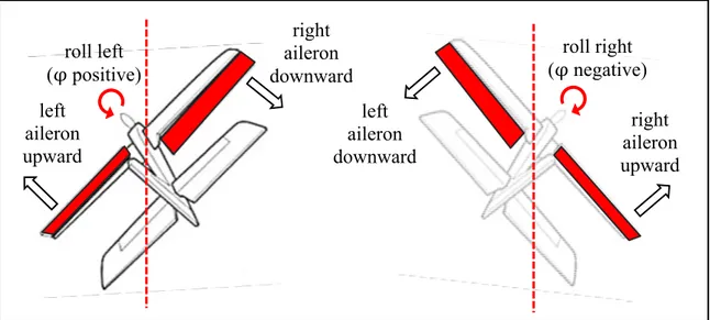
The ailerons control the aircraft to roll around the longitudinal body axis . To control aircraft to roll, the motion of the aileron incorporated on one wing must be simultaneous complemented by the opposite motion of the aileron incorporated on the other wing. If the aileron on the left wing is lowered, the aileron on the right wing is raised. The wing with the raised aileron goes down because the force required to lift it through a stream of air is decreased. The wing with the lowered aileron goes up because the force of lift is increased (Venkata et Chaitanya, 2009). Thus, the aircraft is rolled to the left. The roll angle is defined by φ. By convention, it will have a positive roll angle if the right wing is pivoted upwardly
: pitch axis : roll axis : yaw axis rudder θ right elevator left elevator right aileron left aileron right slats left slats left spoilers right flaps left flaps
and the left is rotated down. Otherwise, there will be a negative roll angle (McLean, 1990). Figure 1.2 illustrates the ailerons motions effect on the aircraft motion.
Figure 1.2 The ailerons’ effects on the aircraft motion Adapted from Venkata et Chaitanya (2009)
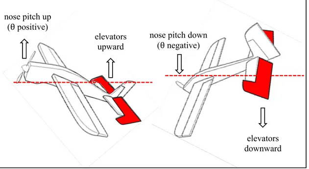
The elevators control the aircraft to pitch around the lateral body axis . Two elevators are located on both sides of the horizontal stabilizer of the aircraft tail unit. By changing the position of the elevators the force of lift increases or decreases. They can move simultaneously and in the same direction. When they move upward, the force of lift is decreased. Then the nose is forced upward and the tail is forced down. Similarly when the elevators move downward, the force of lift is increased. The nose is forced to drop and the tail is forced upward (Venkata et Chaitanya, 2009). The pitch angle is defined by θ. By convention, when the elevators are raised so it will have a positive pitch angle, otherwise there will be a negative pitch angle (McLean, 1990). Figure 1.3 illustrates the elevators motions effect on the aircraft motion.
roll left (φ positive) left aileron upward right aileron downward roll right (φ negative) left aileron downward right aileron upward
Figure 1.3 The elevators’ effects on the aircraft motion Adapted from Venkata et Chaitanya (2009)
The rudder controls the aircraft to yaw around the vertical body axis . The rudder is a movable surface located on the vertical stabilizer of the tail unit. By changing the position of the rudder the aircraft change direction from side to side by redirecting the air fluid past the fuselage.
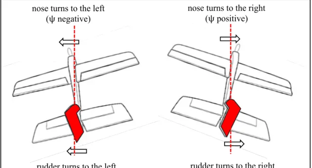
If the rudder pivots laterally to the left, the nose of the aircraft turns to the left. Similarly, if the rudder pivots laterally to the right, the nose of the aircraft turns to the right (Venkata et Chaitanya, 2009). Alone, the rudder will turn an aircraft, but much more slowly than if ailerons are also used in conjunction. In practice, both ailerons and rudder are used together to co-ordinated turns of an aircraft. Operating as well, ailerons and the rudder are compensating for the adverse yaw phenomenon. The yaw angle is defined by ψ. Conventionally, when the aircraft turns right, the yaw angle is positive. Otherwise, it is negative (McLean, 1990). Figure 1.4 illustrates the rudder motions effect on the aircraft direction. elevators upward nose pitch up (θ positive) elevators downward nose pitch down
Figure 1.4 The rudder’s effects on the aircraft motion Adapted from Venkata et Chaitanya (2009)
1.1.2 Secondary control surfaces
In a standard aircraft, the main secondary control surfaces are flaps, slats, spoilers and air brakes. Several flap sections located on the inboard two-thirds of the wing trailing or leading edges. The simple flaps called also split flaps pivot only. The complex flaps called also slotted flaps extend and come down. The Krueger flaps extend and camber. Flaps are deployed during the take-off or the landing approach to improve the aerodynamic characteristics of the wing. Unlike flaps, slats have a nozzle like a slot between the high-lift device and the wing. They are usually located on the wing leading edge. Slats extend the wing edge and they sit like a glove on the edge. Spoilers, also called lift dumpers, are used to reduce the force of lift leading to a loss of altitude without increasing airspeed. Also, they can be used asymmetrically to contribute in the aircraft's roll. Air brakes are designed elsewhere on the aircraft and are usually deflect symmetrically outwards from the fuselage in opposite sides to decrease the aircraft speed (Venkata et Chaitanya, 2009).
rudder turns to the left rudder turns to the right nose turns to the left
1.2 Concept of redundancy and FTC
Hardware redundancy is very important for the purpose of FTC systems, to deal with faults, failures and malfunctions (Isermann, 2006). When a fault, failure or malfunction occurs, the control law will be reconfigured among the faulty original actuators and redundant actuators if the faulty original actuators cannot tolerate the fault by themselves. The use of these redundant control surfaces provides the possibility to maintain the desired performance in the case when original control surfaces become faulty. An example for a redundant actuator is the horizontal stabilizers which can be used in the case of elevators’ failures. Also, engines can replace a failed rudder, by using them differentially to create yaw (Alwi, Edwards et Tan, 2011). Secondary control surfaces can also be used as redundant control surfaces. The spoilers for example, which are originally deployed to reduce aircraft speed, can also be used asymmetrically to contribute in the aircraft's roll, which is normally ensured in principle by the ailerons (Alwi, Edwards et Tan, 2011).
1.3 Avionic systems history
Otto Lilienthal (1848-1896) was the first pilot that successfully used the vertical tail of his self-made glider for lateral stabilization in Germany, 1894 (Christopher, Thomas et Hafid, 2010). Since that, the technology of Flight Control (FC) Systems has continued to grow. During the 1920s, and for many of the decades that followed, most aircrafts were designed to be statically stable, and the process of automated aircraft stability was further improved by using mechanical and mechanical-hydraulic systems. Around the 1950s, the first concept of Fly-By-Wire (FBW) systems using analog Flight Control Computer (FCC) was introduced. In 1972, with the increasing complexity and speed of aircraft, digital FBW systems are performed by NASA, and then it was made commercial in 1987.
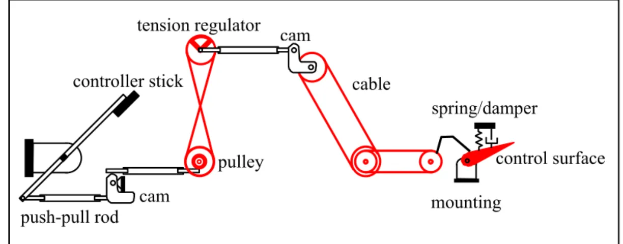
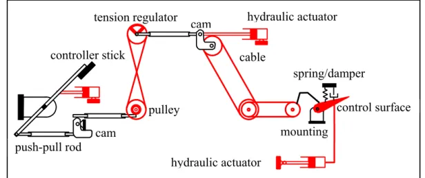
Mechanical systems were designed using only mechanical devices as cables and pulleys. They were used in early aircraft and are still used in recent light aircraft, as in the control system used in the Cessna Skyhawk (Yoney, 2010). However, the control loads become too excessive for such systems in the case of larger aircraft. To overcome this problem, so-called
control tabs are added to provide aerodynamic relief, as those used in the Boeing 707 (Christopher, Thomas et Hafid, 2010). Figure 1.5 illustrates the principle of the mechanical flight control system.
Figure 1.5 The principle of the mechanical flight control system Adapted from Collinson (2013)
Mechanical flight control systems prove not reliable when size, speed and flight envelopes of the aircraft are increased. This led to add hydraulic power systems. The hydraulic power system links between the mechanical device and the pilot. The resulted hydro-mechanical flight control systems increase the effectiveness of the control surface. However, the main drawbacks are the structural complexity and the weight of the hydraulic power. The hydro-mechanical system was implemented for the first time on the De Havilland Comet in 1949 and on the Boeing 707 in 1954. In 1969, the Boeing 747 and Concord were the first commercial aircrafts to have a complete hydro-mechanical system (Christopher, Thomas et Hafid, 2010), (Atul Garg, 2013). Figure 1.6 illustrates a mechanical-hydraulic flight control system.
In recent FBW systems, the mechanical devices, linking between the pilot and the hydraulic power, have been replaced by electrical wirings connected to each other using the Flight Control Computer (FCC). push-pull rod controller stick tension regulator cam pulley cam cable spring/damper mounting control surface
Figure 1.6 The mechanical-hydraulic type of a flight control system Adapted from Collinson (2013)
Based on the desired trajectory and the sensors’ measurements, the FCC computes the required control surface deflections and gives the associated control signals to the actuators. The FBW systems have less weight than those used heavy mechanical devices and hydraulic power, which significantly reduces the aircraft weight. The design and maintenance of the FBW systems are much simpler. The analog FBW systems are designed in the 1950’s, followed by the digital FBW in the 1970’s. FBW systems are used in most recent civil and military aircrafts (Christopher, Thomas et Hafid, 2010), (Atul Garg, 2013). Figure 1.7 illustrates a FBW flight control system.
Figure 1.7 The FBW type of a flight control system Adapted from Collinson (2013)
push-pull rod controller stick tension regulator cam pulley cam cable spring/damper mounting control surface hydraulic actuator hydraulic actuator Aircraft dynamics Flight Control Computer Air data sensors Pilot’s stick
Aircraft motion Aerodynamics
Control surface Electric signal
Actuator feedback Control signal
1.4 Actuator faults, failures and malfunctions
In the field of fault diagnosis, different technological terminologies such as fault, failure and malfunction are used. To avoid confusion between these terminologies, the distinction between them must be clarified. Based on Isermann definition (Isermann, 2006), The IFAC technical committee (Isermann et Ballé, 1997) makes the following definitions: “A fault is an unpermitted deviation of at least one characteristic property (feature) of the system from the acceptable, usual, standard condition.” Based on the above statement, an actuator fault is associated with an abnormal behavior of the control surface, which may not necessary affect the overall function of the control surface. It may be small or hidden and abrupt or intermittent. This makes it very hard to online detect and diagnose. When an actuator fails, it is still usable but becomes less effective. The loss of hydraulic fluid is considered one of the reasons for the occurrence of actuators’ faults. Figure 1.8 illustrates examples of an actuator fault which corresponds to a loss of effectiveness.
Figure 1.8 A type of an actuator fault: The loss of effectiveness Adapted from Isermann (2006)
0 2 4 6 8 10 12 -15 -10 -5 0 5 10 15 Ac tuat or def lec tion (deg ) time (s)
Desired actuator position True actuator deflection
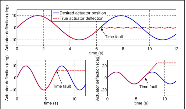
Based on the same reference, the failure has allowed the following definition: “A failure is a permanent interruption of a system’s ability to perform a required function under specified operating conditions.” Based on the above definition, the failure can be considered as the result of one fault or a set of faults. Therefore the resulted failure compromises the actuator operation, and the actuator will be not usable and its replacement is emergently needed. There are two major types of actuator failures. The control surface may float freely at the zero position and do not provide any aerodynamic effect on the aircraft dynamics as illustrated in the top of Figure 1.9. It can also be jammed at an unknown position or at the actuator limit position and becomes stuck and immovable for the remaining flight time as illustrated in the bottom of Figure 1.9. These failures are the results of the break of one or many mechanical devices which ensure the link between the control surface and the associated actuator.
Figure 1.9 The different types of existing actuator failures Adapted from Isermann (2006)
Finally, the actuator malfunction is an event that causes an intermittent deficiency in the accomplishment of the actuator overall function. It interrupts temporarily the actuator’s function resulting from increased actuator stress (Isermann, 2006). As well as the failure, the
0 2 4 6 8 10 12 -10 0 10 Ac tuat or de flec tion (deg ) time (s) Desired actuator position True actuator deflection
0 5 10 -10 0 10 Ac tu at or def lec tio n (de g) time (s) 0 5 10 -20 0 20 Ac tu at or def lec tio n (de g) time (s) Time fault Time fault Time fault
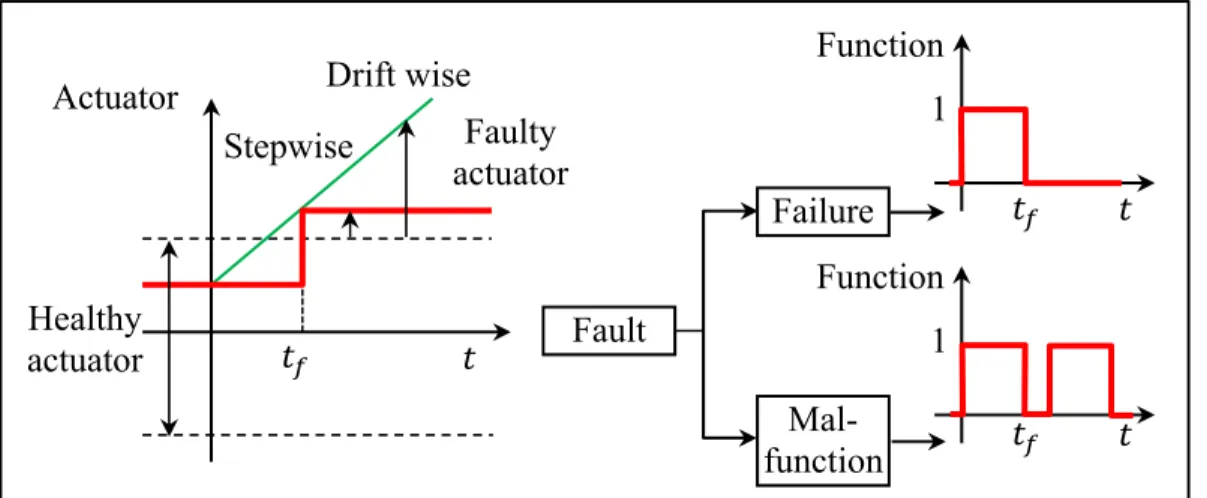
malfunction results also from one fault or from a set of faults, except that the malfunction takes less time than the failure. Figure 1.10 shows the development of the failure and the malfunction from the fault and their features.
New types of faults have been introduced when Taber and Normand found that neutrons generated by cosmic rays are capable of causing Single-Event Upsets (SEUs) in modern FBW avionics systems responsible for producing actuator control signals during flight (Taber et Normand, 1995). The resulting inappropriate actuator deflection affects aircraft dynamics and stability.
Figure 1.10 Development of the failure and the malfunction from the fault and their features Adapted from Isermann (2006)
Research on the effects of such faults has been grown in the avionics community since 2002. Therefore, NASA and other research centers formed a research partnership to study the effects of cosmic rays on the flight systems (Belcastro, Eure et Hess, 2006).
In 2006, NASA has tested new computer architecture under the impact of neutrons. This architecture was able to detect failure caused by a neutron by comparing the bits. Once the failure is detected, the designed architecture uses and remain using the last computed control law until the failure disappearance (Belcastro, Eure et Hess, 2006). In 2013, new model types of cosmic rays are developed based on the fault emulation process which is based
Actuator Drift wise
Healthy actuator Stepwise Faulty actuator Fault Failure Mal-function Function 1 Function 1
mainly on the use of the SEU controller of Xilinx® (Hobeika et al., 2013). This study revealed that about 10 % of the faulty outputs fit existing models such as locked in place, loss of effectiveness, floating around trim and hard over. The other 90 % displayed new faults behaviors and they are illustrated in detail in chapter 3.
For the rest of the thesis, the term fault is used because it is widely recognized that faults are unwanted malfunctions of a system, whereas a failure is the result of the total loss of a function (Christopher, Thomas et Hafid, 2010). In addition, a focus on actuator faults is done because, in fact, sensors’ failures do not degrade the performance and the stability of commercial aircrafts. Furthermore, the sensor failure can be handled either by using redundant sensors or by estimating the faulty sensors’ measurements using some existing techniques (Chen et Speyer, 2004). However, the FDD process developed in this thesis is capable of handling faulty actuators’ signals as well as faulty sensors’ measurements.
1.5 Fault-Tolerant systems: General overview
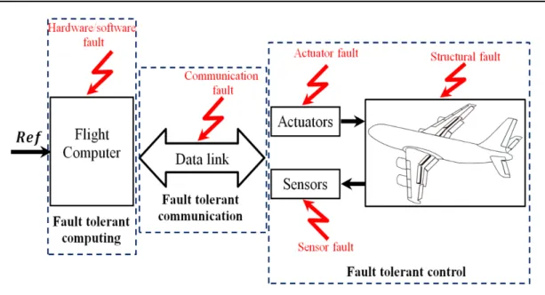
In the context of overall flight computer structure environments, three major types of fault-tolerant systems can be designed depending on the type of occurred faults. When faults occur in the hardware or software of the flight computer, then a Fault-Tolerant Computing system will be required to handle this kind of faults. When faults occur in actuators, sensors or structure of the aircraft, then a Fault-Tolerant Control system will be required to handle this kind of faults. Finally, if the faults affect the communication links, a Fault-Tolerant Communication system will be required. This thesis elaborates the Fault-Tolerant Control (FTC) systems and especially in the case of actuators’ faults. Figure 1.11 illustrates a basic flight computer system and its faults (Pastor, Lopez et Royo, 2007).
Figure 1.11 A basic flight computer system and its faults Adapted from Pastor, Lopez et Royo (2007)
1.5.1 Objective of a Fault-Tolerant Control system
A simple conventional feedback control can be very limited, and brings the system to undesired behaviors or even to instability in the presence of an actuator failure. Therefore, the FTC systems have the ability to automatically accommodate the fault to preserve aircraft stability and maintain desired performance in the presence of such faults. The main task of a FTC system is to reconfigure control laws to ensure stability and maintain the desired performance of the system, not only in the normal situation but also when some actuators become failed. FTC systems are classified into two main classes: Passive Fault-Tolerant Control (PFTC) systems and Active Fault-Tolerant Control (AFTC) systems.
1.5.2 Passive and Active Fault-Tolerant Control system
PFTC systems are usually closely related to robust control without requiring any information on faults’ parameters nor controller reconfiguration or adaptation. They have the drawbacks that they are reliable only for a closed class of faults and they degrade system performance
even when no faults occur. However, AFTC systems react against component failures using online reconfiguration so that aircraft stability can be preserved and the desired aircraft performance can be maintained. AFTC systems depend on online explicit knowledge of faults’ parameters generated from the so-called FDD process. The FDD process operates as a health supervision module of the system and decides to reconfigure the flight controller when faults occur. In some practical applications, PFTC systems are considered as a complement of AFTC systems. Indeed, PFTC systems are required during execution of the fault detection and diagnosis functions (Zhang, Parisini et Polycarpou, 2004), where they are solicited to preserve the stability of the faulty system until AFTC systems are adapted to the new faulty scenario. A main critical criterion in AFTC systems is the FDD process speed constraint which can be defined by the time required to detect and diagnose a fault. Furthermore, the accuracy of the identified fault information and the robustness of the FDD process to external disturbances are considered important issues. Figures 1.12 and 1.13 illustrate the two main families’ architectures.
Figure 1.12 PFTC system architecture Adapted from Blanke et Schröder (2006)
Actuators Sensors Fault Robust Flight Control Ref Output