HAL Id: hal-02056363
https://hal-mines-albi.archives-ouvertes.fr/hal-02056363
Submitted on 5 Mar 2019HAL is a multi-disciplinary open access archive for the deposit and dissemination of sci-entific research documents, whether they are pub-lished or not. The documents may come from teaching and research institutions in France or abroad, or from public or private research centers.
L’archive ouverte pluridisciplinaire HAL, est destinée au dépôt et à la diffusion de documents scientifiques de niveau recherche, publiés ou non, émanant des établissements d’enseignement et de recherche français ou étrangers, des laboratoires publics ou privés.
Infrared Heating Modeling of Thermoplastic Sheets in
Thermoforming Process
Sylva Andrieu, Yannick Le Maoult, Fabrice Schmidt
To cite this version:
Sylva Andrieu, Yannick Le Maoult, Fabrice Schmidt. Infrared Heating Modeling of Thermoplastic Sheets in Thermoforming Process. International Conference of Polymer Processing Society, Jun 2002, Guimarès, Portugal. �hal-02056363�
Infrared heating modelling of thermoplastic sheets
in thermoforming process
S. Andrieu, F. Schmidt and Y. Le Maoult
CROMEP, EMAC, Campus Jarlard, 81013 ALBI Cedex 09, France
Abstract
The thermoforming process involves a heating step before forming, the thermoplastic sheet being warmed up using infrared heaters. The forming temperature is above glass transition temperature for amorphous polymers and slightly below crystalline temperature for semi-crystalline polymers. Today, industrial thermoforming machines generally feature an infrared oven with ceramics heaters that emit infrared long waves. Other electric radiant heaters like quartz tubes or halogen lamps are also used, but not as much. The heating step of the thermoforming process could be improved to obtain best sheet’s temperature distribution which governs the thermoformed part thickness distribution.
Many parameters influence the heating step such as geometry and number of heaters, heaters temperature, position of the heaters, distance between heaters and sheet…
An experimental infrared heating device is developed in order to measure the effect of the different parameters. Software called PLASTIRAD based on the volume method is used to simulate the infrared heating of polymers in order to optimise the infrared oven of an experimental set-up.
1- Introduction
The principle of thermoforming process is sketched in Fig.1. Thermoforming of thermoplastic sheets requires a heating step before forming. This heating step induces temperature gradients inside the thermoplastic sheet which in turn determines the thickness distribution and consequently the quality of the final part. Due to low polymer thermal conductivity (0.29 W/m/K for PET), this step is performed using infrared heaters which allow rapid heating of the polymers.
1. Heating step 2. Departure of the oven Mould climbing
3. Forming step using vacuum
4. Removal of the mould Figure 1 – The different steps of thermoforming
Many polymers are frequently used in the thermoforming process such as Polystyrene, Polypropylene, ABS, PET, HIPS… [1]. In the case of PET (crystallisable), the forming temperature is in the range between 130 to 145 °C [2]. Generally thermoforming machines are equipped with ceramic heaters rather than halogen lamps which are currently used in injection stretch-blow moulding machines. The industrial problematic is thus to evaluate the capability of halogen lamps in thermoforming process. Heating with halogen lamps presents different advantages such as fast heat-up and cool down, fast temperature-change responsiveness, zoning capability. These aspects must be considered to figure out
the right heating process tuning that permit an optimised temperature distribution and consequently improve the thermoformed parts quality.
A lot of different process parameters should be investigated. Therefore, we have developed an experimental infrared heating set-up to study the influence of these parameters. Numerical simulations are performed in order to compute temperature distribution in the thermoplastic sheet versus position of lamps. Computations have been processed using the software called PLASTIRAD based on a control-volume method and taking into account halogen lamps and thermoplastic sheet spectral properties.
2- Characterisation of the infrared heaters
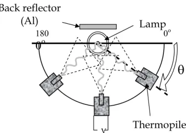
An experimental set-up shown in Fig.2 has been developed in order to measure with a thermopile the spatial directivity of the infrared lamps used in industrial applications [3].The thermopile’s bandwidth extends between 0.6 and 25 µm. The thermopile moves around the lamp on half circle. It intercepts the radiation in each direction from 0 up to 180° with an increment of 10°. The measured intensity is normalised in relation to the maximum intensity observed in all directions.
Figure 2 – Experimental set-up used in order to measure spatial directivity
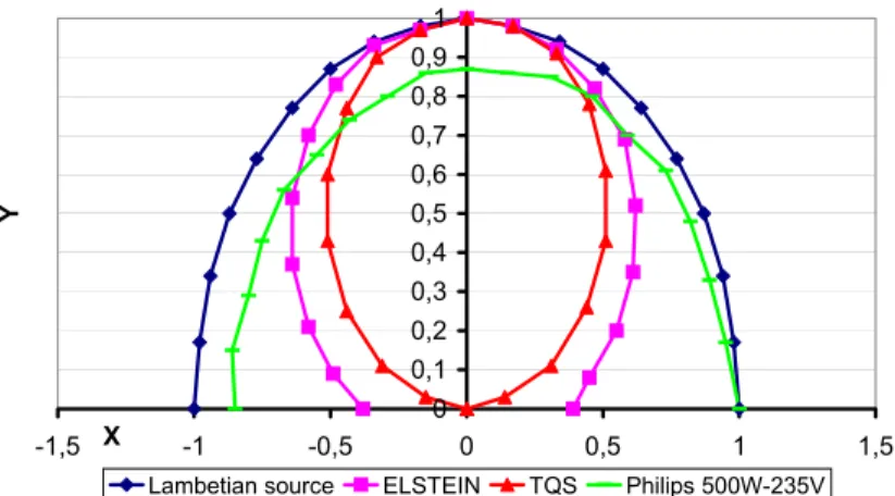
A comparative directivity study was performed on ceramic heaters (Elstein 650W), quartz tube (TQS 600W) and halogen lamps. These electric radiant heaters used in thermoforming process present a maximum emission in different range of wavelength (long, average and short respectively). In Fig.3, for each kind of radiant heater, the normalised intensity is plotted versus the angle in comparison with a Lambertian source. The halogen lamp exhibits the closest behaviour to lambertian source compared to ceramic heater and quartz tube. Numerical simulations could be performed using the PLASTIRAD software that computes energy emitted using a view factor calculation.
Lamp
180
0
o0
oThermopile
Back reflector
(Al)
θ
V0 0,1 0,2 0,3 0,4 0,5 0,6 0,7 0,8 0,9 1 -1,5 X -1 -0,5 0 0,5 1 1,5 Y
Lambetian source ELSTEIN TQS Philips 500W-235V
3- Experimental infrared heating set-up
An experimental infrared heating set-up (see Fig. 4, 5 and Table 1) is developed in order to measure the influence of the process parameters on the heating step of the thermoforming process. This original set-up is designed like a manual thermoplastic machine. It is constituted of an aluminium structure (170*91*130 cm3) that supports a metallic square frame clamping the thermoplastic sheet and a movable infrared oven. Three dimensions of sheet’s effective surfaces (500*500, 350*350 and 150*150 mm2) are available to study the effect of the dimension on the sheet‘s sag for example. In the oven’s frame two different modulus could be adapted. One modulus is constituted of a diffusive flat aluminium reflector and eighteen 1000W-Philips halogen lamps (13195Z/98-235V). In the second modulus, individual diffusive aluminium reflectors (IR3-Philips) are adapted on six 1000W (13713Z-235V) and six 500W Philips lamps (13169Z-(13713Z-235V).
This device is designed to control many parameters. The distance between the thermoplastic sheet and the lamps is adjustable. The lamps position and reflectors could be changed. Each lamp is power-regulated. Infrared oven of industrial thermoforming machine (750*750 mm2) could be adapted in this device to study the sheet’s temperature distribution that induces.
This set-up is equipped with a CDD camera to measure sheet’s sag versus heating time and an infrared camera (880 LW AGEMA) to measure surface temperature during heating using a polished aluminium mirror. Thermocouples can be added to measure air temperature between oven and thermoplastic sheet.
Figure 3 – Infrared heater’s directivity
4
3
5
1
9
2
6
7
8
Figure 4 – Experimental infrared heating set-up plan Figure 5 - Experimental infrared heating set-up
Table 1 – Designation Number Designation 1 Aluminum structure 2 Metallic frame 3 Thermoplastic sheet 4 Infrared oven 5 Electric regulation 6 CCD camera 7 Infrared camera 8 Aluminium mirror 9 Fixing screws
4- Control-volume model
The PLASTIRAD software has been developed in order to compute heat transfer between polymer and heaters during an infrared heating step. It is based on a control-volume method [4]. Previous comparisons performed between numerical simulations and experiments have validated the model [5]. The thermoplastic sheet is meshed (solid mesh) using FEM quadratic elements adapted in control volumes. The halogen lamps used are composed of a coiled tungsten wire enclosed in a quartz tube (diameter: 10 mm) filled with a mixing of halogen and inert gas. Spectral properties of tungsten filament, filling gas and quartz tube have been measured in previous works [5,6]. The tungsten filament and the quartz tube are modelled as half-cylinders. Each half-cylinder is meshed (shell mesh) using linear elements.
The temperature balance equation that takes into account radiative and conductive transfers is integrated over each control volume and over time.
∫∫
∫∫
∫∫
∆ ∆ Γ ∆ Γ Γ − Γ − = ∂ ∂ t V t t r c p dVdt q nd dt q nd dt t T C r .r r .rρ
(1)Where V is the control volume, qc and qr the conductive and radiative fluxes and Γ the surface.
In the model, a uniform source temperature is assumed for the tungsten wire and the quartz tube. Temperatures are computed at the cell centres of each control-volume.
The amount of incident radiation that reaches each elements of the sheet is computed using a contour integration method based upon Stoke’s theorem [7]. This method permits good accuracy and is lower time-consuming than other methods, e.g. the Monte-Carlo method.
∫ ∫
Γ Γ=
i j j i H H ijrd
r
d
r
S
F
ln
r
r
2
1
π
(2)Where subscript H refers to the heater i and j to the elementary heater and sheet surfaces. SH is the total heater’s surface. Γi and Γj are the elementary surfaces coming from the mesh. r refers to the distance between the heater and the sheet surface.
(
)
∫
∫
∆ ∆+
=
=
Φ
λ λ λ λ λ λ λε
π
λ
τ
π
λ
τ
L
T
d
S
S
F
d
T
L
S
S
F
y
Q Qi j Qi Q ij Wi Q j Wi W ij ij0
0(
)
0(
)
(3)Where FijW and FijQ are the view factors referring to tungsten and quartz respectively, S is the surface, τQλ the quartz transmittivity, ελ is the spectral tungsten emissivity, Lλ0 is the blackbody intensity and λ is a given wavelength.
The thermoplastic sheet temperature (# 140°C) is lower than the halogen lamp temperature (# 2000°C) so the sheet could be considered as a cold material. Within the sheet thickness, the Beer-Lambert’s law gives the transmitted flux:
y k ij ij y y e λ − = Φ = Φ ( ) ( 0) (4)
kλ is the spectral absorption coefficient.
5- Numerical simulations
5.1 Process parameters
Simulations are performed to conceive the original configuration of the infrared oven in the experimental heating set-up. The sheet’s temperature depending on the position of the lamps in the oven was first analysed. We proceeded to heat a PET sheet (500*1.5*500 mm) with eighteen 1100W(rated power)-Philips halogen lamps (14105Z/98) supplied with 1000W. The distance between lamps and sheet is 50 mm.
The spectral properties of PET have been obtained from previous works [8]. Tungsten wire and quartz tube are modelling as half cylinders. Their temperatures, necessary for all numerical simulations are consigned in Table 2.
Table 2 - Operating conditions
Tungsten wire Quartz Tube
Temperature (K) 2539 856
The sheet is meshed (solid-mesh) using 900 elements (15*4*15, length*thickness*width). Quartz tube and tungsten wire of each halogen lamp are meshed with 25 elements (5*5, length*circumference). Three different intervals between lamps 60, 70 and 80 mm are compared with the zigzag configuration described in Fig. 6, 7 and 8 respectively.
Table 3 – Heating times
60 mm interval 70 mm interval 80 mm interval
Heating time (s) 50 60 74
For the three different configurations, the thermoplastic sheet requires a different heating time (see Table 3) in order to reach the forming temperature. After this heating time, the thermoplastic sheet undergoes the air convection cooling. In Fig. 9, the sheet centre temperature (x = 250 mm and z = 250 mm) is plotted versus time for the surface exposed to radiation (front surface) and the back surface. In the section plane (z = 250 mm), temperature is plotted versus x for the front surface and the back
z
x
z
x
z
x
Figure 6 – 60 mm intervalFigure 9 – Temperature versus heating time
Figure 7 – 70 mm interval
surface in Fig. 10 and 11 respectively. In the same way, temperature versus z in the plan (x = 250 mm) is plotted in Fig 12 and 13 for the front surface and the back surface respectively.
5.2 Results
Fig.9 demonstrates the temperature evolution versus increased intervals between lamps axis. The heating time to reach the forming temperature increases with the distance between lamps axis. On the other hand, the distribution temperature versus x is better with the 80 mm interval. Actually, with 60 mm interval, the sheet sides are not correctly heated (weakest temperature). A comparison of the different temperature profiles shows that the x direction is privileged. It is due to the lamp geometry, as the heating is better in the x direction perpendicular to the lamps axis. The jump around z=300 mm in Fig. 12 and 13 is due to the presence of a lamp right above the middle line x=250mm from z=250 mm up to z=500 mm. A 5°C gap between front and back surface temperatures is observed. According to all these representations, in our numerical simulations, 80 mm interval simulation is the configuration which gives the best temperature distribution.
6- Energy criteria
6.1 Distribution energy and overall energy criteria Figure 10 – Front surface
temperature versus x
Figure 11 – Back surface temperature versus x
Figure 12 – Front surface temperature versus z
Figure 13 – Back surface temperature versus z
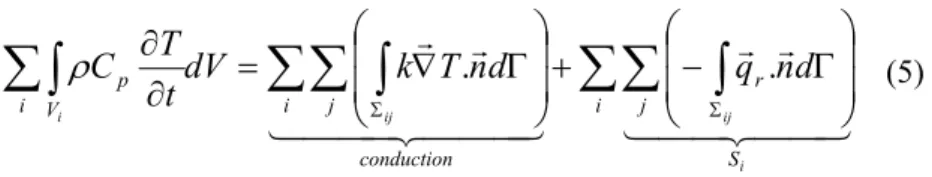
The main idea is to use energy criteria to compare different simulations independently of the dimensions. Heat balance equation (Eq. 1) could be rewritten (see Eq. 5) in order to deduce the source term Si corresponding to the energy received by each control volume.
(5)
Where Si is the source term. The PLASTIRAD software computes the source term for each control volume. The distribution energy criterion Ri presents the discrepancy between the source term of each element and the maximum source term found over the entire thermoplastic sheet.
(6)
Ri varies from 0 to 1. Therefore, an arrangement that gives Ri close to 1 is the eventual goal. This distribution energy criterion is presented for 60 mm, 70mm and 80 mm intervals in Fig. 14,15 and 16 respectively and for the front surface.
∑∑ ∫
∑∑ ∫
∑∫
Γ − + Γ ∇ = ∂ ∂ Σ Σ i S j r conduction i j i V p i ij ij i d n q d n T k dV t T C 4 4 3 4 4 2 1 r r 4 4 4 3 4 4 4 2 1 r r . .ρ
max S S R i i = Figure 15 – 70 mm interval distribution energy criterionFigure 16 – 80 mm interval distribution energy criterion Figure 14 – 60 mm interval
Ri discrepancy for the 60 mm interval is of 50%, for the other configurations is about 30%. The configuration that gives the best uniformity is 80 mm interval except a energy concentration in the sheet centre.
Moreover, an overall energy criterion is introduced as a complementary tool in order to compare the infrared radiation efficiency for different configurations. The criterion used E is defined by the ratio energy received by energy emitted:
In our simulations, we use eighteen 1000W halogen lamp without reflectors so ΣPL=18*1000/2=9000W. Considered that, the calculations of the overall energy criterion are compiled in Table 4.
Table 4
60 mm interval 70 mm interval 80 mm interval
E (%) 17 15 14
To optimize the infrared heating, a power regulation is planned for introduction in the numerical simulations as well as in the experimental infrared heating set-up. An analysis of Fig.16 that is the representation of the best configuration (80 mm interval), induces the idea of decreasing the power of the lamps which are located in the zone surrounding the Ri maximum position: the lamps that are thus power-regulated are indicated in Fig. 17. The new Ri distribution (see Fig. 18) is more homogenous and the overall energy criterion for this particular setting is 13%. The choice of the final configuration depends on what is expected, in our case, it is in a first stage to obtain a temperature uniformity over the all sheet. Consequently, the chosen configuration is the 80 mm interval.
z
x
80% 90% 90% 90% 90% 90% 90% L i P S E ∑ ∑ = Figure 18 – 80 mm interval distribution energy criterion withpower regulation Figure 17 – 80 mm with power
regulation
7. Conclusion
Numerical simulations of PET sheet heating with halogen lamps have been performed to optimize an infrared oven. Due to lamps geometry, a direction is privileged by the choice of the orientation of the lamps. In our case, this direction is perpendicular to the lamp axis. Except the sides of the sheet, a satisfactory temperature distribution is obtained.
Energy criteria have been used to compare the different simulations. The distribution energy criterion is useful to avoid a spatial energy distribution. The overall energy criterion is a tool to evaluate efficiency of the heating step. So temperature computations and energy criteria allow to configurate lamps position in the infrared oven.
Further numerical model developments will permit to integrate the real direction beam into the sheet and the efficiency of reflectors. Moreover, the experimental infrared heating device will permit to compare experimental measurements and numerical simulations and finally to validate the model developments
Acknowledgements
The authors would like to thank our industrial partners Philips Lighting and EDF-Renardières Companies for technical support and funding.
References
1. J. L. Throne, Technology of thermoforming, Hanser/Gardner Publications, 1996 2. Adolf Illig, Pratique du thermoformage, publisher: Hermès sciences, 1999, in French
3. S. Monteix, R. Diraddo, F. Schmidt, Profiles infrared radiative heating in blow molding and
thermoforming, PPS’98- North American Meeting, Toronto, August 17-19, 1998
4. S.V. Patankar (Ed.), Numerical Heat Transfer and Fluid Flow, McGraw-Hill, New York, 1980 5. S. Monteix, F. Schmidt, Y. Le Maoult, R. Ben Yedder, R.W. Dirrado, D. Laroche, Experimental
study and numerical simulation of preform or sheet exposed to infrared radiative heating, Journal
of Materials Processing Technology, 119, pp. 90-97 (2001)
6. Y. Le Maoult, F. Schmidt, M. El Hafi, Measurements and calculation of preform infrared heating, Proceedings of the Fourth International Workshop on Advanced Infrared Technology and Applications, Firenze, September 1997
7. R. Rammohan, Efficient evaluation of diffuse view factors for radiation, Int. J. Heat Mass Transfer., 39 (6), 1281-1286, (1996)
8. S. Monteix, F.M. Schmidt, Y. Le Maoult,G. Denis and M. Vigny, Recent issues in preform
radiative heating modelling, Proceeding of the 17th international conference of the Polymer Proceeding Society, May 21-24 (Montreal Canada), 2001