HAL Id: hal-01664259
https://hal.archives-ouvertes.fr/hal-01664259
Submitted on 14 Dec 2017HAL is a multi-disciplinary open access archive for the deposit and dissemination of sci-entific research documents, whether they are pub-lished or not. The documents may come from teaching and research institutions in France or abroad, or from public or private research centers.
L’archive ouverte pluridisciplinaire HAL, est destinée au dépôt et à la diffusion de documents scientifiques de niveau recherche, publiés ou non, émanant des établissements d’enseignement et de recherche français ou étrangers, des laboratoires publics ou privés.
Christophe Gransart, Thomas Gallenkamp, Eneko Echeverria, Stephan
Pfletschinger, Stephan Sand, Paul Unterhuber, Marion Berbineau, Inaki Val,
Aitor Arriola, Cyril Adrian, et al.
To cite this version:
Christophe Gransart, Thomas Gallenkamp, Eneko Echeverria, Stephan Pfletschinger, Stephan Sand, et al.. Projet ROLL2RAIL: Deliverable D2.3 - State of the Art in Radio Technologies and Recom-mendation of Suitable Technologies. [Research Report] IFSTTAR - Institut Français des Sciences et Technologies des Transports, de l’Aménagement et des Réseaux. 2015, 94p. �hal-01664259�
NEW DEPENDABLE ROLLING STOCK FOR A MORE
SUSTAINABLE, INTELLIGENT AND COMFORTABLE
RAIL TRANSPORT IN EUROPE
D2.3 – State of the Art in Radio Technologies and
Recommendation of Suitable Technologies
Due date of deliverable: 30/10/2015
Actual submission date: 28/10/2015
Leader of this Deliverable: Christophe Gransart (IFSTTAR) Reviewed: Y
Document status
Revision Date Description 1 07/07/2015 First issue
2 30/07/2015 Contribution from Ikerlan
3 11/09/2015 Contribution from DLR, Vossloh, update from Ikerlan 4 29/09/2015 Contribution from Thales, USBG, IFSTTAR
5 11/10/2015 First Complete version
6 13/10/2015 Executive summary completed and updated to last official template for deliverables (IFSTTAR & CAF I+D).
7 16/10/2015 Revised version according to the internal review 8 20/10/2015 Complete version with annex
9 28/10/2015 Version after TMT comments
Project funded from the European Union’s Horizon 2020 research and innovation programme
Dissemination Level
PU Public X
CO Confidential, restricted under conditions set out in Model Grant Agreement
CI Classified, information as referred to in Commission Decision 2001/844/EC
REPORT CONTRIBUTORS
Name Company Details of Contribution
Thomas Gallenkamp Bombardier
Transportation (BT)
BT has contributed with general review from technical point of view.
Eneko Echeverría CAF I+D (CAF) CAF I+D, as WP2 Leader, has contributed in general review from quality/formal aspects and adapting the document to last version of the template of deliverables.
Stephan Pfletschinger Stephan Sand
Paul Unterhuber
DLR (DLR) DLR has written TETRA (2.2.1), LDACS1 (3.3.2), WIFI (4.1.6) and DSRC/ITS-G5-802.11p (5.1) chapters.
Christophe Gransart Marion Berbineau
IFSTTAR (IFST) IFST, as Task Leader, has contributed writing Executive Summary, Introduction, Conclusions and consolidating all contributions from other partners. Moreover, they have written Millimetric Communications (2.2.4), UWB (2.2.3) and Cognitive Radio (2.2.6) chapters.
Iñaki Val Aitor Arriola
IKERLAN (IK) IK has written WIA-PA (4.1.1), Industrial WLAN Siemens (4.1.2), WirelessHART (4.1.3), ISA 100.11a (4.1.4), WIFI (4.1.6), WISA ABB (4.1.7), Bluetooth (4.1.8), DECT (4.1.9), Lobometrics (4.1.10), OneWireless Honeywell (4.1.11) and Phoenix Contact (4.1.13).
Cyril Adrian THALES (THA) THA has written TETRA (2.2.1), AEROMacs (3.3.3), WIFI (4.1.6) and LTE (4.1.14).
Martin Mayr University of Salzburg (USBG)
USBG has written Aeronautic MANET (3.2.1), ADS-B (3.2.2), VDL Mode 2 (3.3.1), LDACS1 (3.3.2) and AEROMacs (3.3.3). Luis Mesa VOSSLOH (VOSS) VOSS has written a summary from Marathon
Project.
EXECUTIVE SUMMARY
The Roll2Rail project aims to develop key technologies and to remove already identified blocking points for radical innovation in the field of railway vehicles, as part of a longer term strategy to revolutionize the rolling stock for the future. The results will contribute to the increase of the operational reliability and to the reduction of the life cycle costs. This project started in May 2015 and it is supported by the Horizon 2020 program of the European Commission. Roll2Rail is one of the lighthouse projects of Shift2Rail and will contribute to Innovation Program 1. At the end of the project all the results will be further developed, leading to demonstration in real vehicles or relevant environments in Shift2Rail.
Going into detail, this Roll2Rail project covers different rolling stock topics such as Traction (WP1), TCMS (WP2), Car-Body-Shell (WP3), Running-Gear (WP4), Brakes (WP5), Vehicle Interiors (WP6) and transversal activities such as Noise (WP7) and Energy Management (WP8).
In that context, WP2 work package’s concrete goal is to make research on technologies and architectures to allow new generation of train communication systems based on Wireless Transmission for Train Control and Monitoring System (TCMS), functions and Infotainment, CCTV applications, thus reducing or even completely eliminating, on board communication cables and simplifying the train coupling procedure.
The goal of this deliverable on state of the art in radio technologies (D2.3) is to have a snapshot of the main current technologies available and future trends to achieve data transmission in real time. The objective is to collect information of existing, promising or under development technologies and architectures from other fields like aeronautics, industrial, telecommunications or signaling. The report include an overview on hardware, protocols, frequencies, performance, simulators and tools, official institutions and bodies, standards, other research projects or initiatives.
This state of the art studied various technologies in the railway field and also into some others fields: aeronautics, industry and automotive with the hope to have cross-fertilization usage of some technologies.
TABLE OF CONTENTS
Report Contributors ... 2 Executive Summary ... 3 List of Figures ... 6 List of Tables ... 8 1. Introduction ... 92. State of the Art in Railways ... 10
2.1 Radio Technologies Between Trains and Consists ... 10
2.1.1 TETRA ... 10
2.1.2 Project Marathon Experience in Distributed Power Long Trains ... 13
2.1.3 Ultra Wide Band ... 17
2.1.4 Milimeter Communication ... 21
2.1.5 Research Works in the Railway Domain Using UWB, Millimeter Waves and 10 GHz Systems and Cognitive Radio Systems ... 28
2.1.6 Cognitive Radio ... 29
3. State of the Art in Aeronautics ... 33
3.1 Future Aeronautical Communications for Air-Traffic Management ... 33
3.2 Radio Technologies Between Aircrafts ... 34
3.2.1 Aeronautic MANet ... 34
3.2.2 ADS-B ... 34
3.3 Radio Technologies for Plane to Infrastructure Communication ... 37
3.3.1 ICAO VDL Mode 2 ... 37
3.3.2 LDACS ... 39
3.3.3 AeroMACS ... 44
3.3.4 Satellite Communication ... 49
3.4 Suitability for the Railway Domain ... 50
4. State of the Art in Industry ... 51
4.1 Radio Technologies for Embedded Systems into the Factory ... 51
4.1.1 WIA-PA ... 58 4.1.2 WISA / WSAN ... 60 4.1.3 WirelessHART ... 62 4.1.4 ISA100.11a ... 65 4.1.5 ISA100.12 ... 66 4.1.6 WiFi ... 67 4.1.7 Magnetic Induction ... 68 4.1.8 Bluetooth ... 69 4.1.9 DECT ... 73
4.1.10 Industrial WLAN (Siemens) ... 75
4.1.11 Lobometrics ... 76
4.1.12 OneWireless (Honeywell) ... 77
4.1.13 Phoenix Contact ... 78
4.1.14 LTE Technology Overview ... 79
4.2 Suitability for the Railway Domain ... 87
5. State of the Art in Automotive ... 88
5.1 Radio Technologies for Car-to-Car Communication ... 88
5.1.1 ITS-G5 and IEEE 802.11p ... 88
5.1.2 IEEE 802.15.4 ... 90
5.2 Radio Technologies Between Vehicles ... 92
5.3 Radio Technologies for Vehicle to Infrastructure Communication ... 92
5.4 Suitability for the Railway Domain ... 92
LIST OF FIGURES
Figure 1: Frame and multi frame structure of TETRA DMO... 11
Figure 2:RCAS block diagram [1] ... 12
Figure 3:Basic RCAS message [1] ... 12
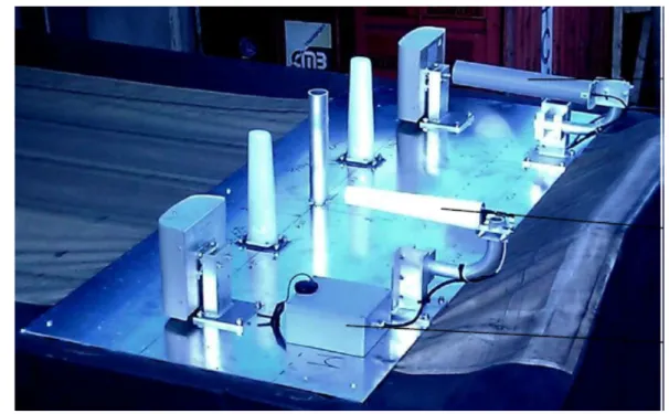
Figure 4: Set of antennas used in the first radio test ... 14
Figure 5: Marathon final test ... 16
Figure 6: UWB Spectrum: FCC Indoor and Outdoor limits ... 17
Figure 7: Spatial Capacity ... 21
Figure 8: Wilocity’s wireless board ... 24
Figure 9: WiGig products from Golem ... 25
Figure 10: IMEC products ... 25
Figure 11: Mr LOOP products ... 26
Figure 12: PERASO dongle ... 26
Figure 13: PERASO components ... 26
Figure 14: Tensorcom products ... 27
Figure 15: Bridgewave products ... 27
Figure 16: Cognitive Radio Concept ... 30
Figure 17: The Future Communications Infrastructure (FCI) for aeronautical communications, including LDACS for air-to-ground communication and AeroMACS for communication between airplanes and the tower at large airports ... 33
Figure 21: Block diagram of an LDACS transmitter ... 40
Figure 23: LDACS Super-Frame Structure [56]. ... 42
Figure 24: LDACS Data Link Layer ... 42
Figure 25: LDACS RL Resource Allocation ... 43
Figure 26: AeroMACS frame with adaptive DL/UL subframe width [62] ... 48
Figure 27: AeroMACS MAC PDU formats [63] ... 48
Figure 28: Wireless technologies in industrial applications [66] ... 51
Figure 30: WIA-PA network topology ... 58
Figure 31: WIA-PA superframe structure ... 58
Figure 33: WISA/WSAN-FA frame definition ... 60
Figure 34: WISA/WSAN-FA telegram definition ... 60
Figure 35: WISA/WSAN-FA characteristics ... 61
Figure 36: WISA/WSAN-FA network ... 61
Figure 37: OSI layers of WirelessHART [72] ... 62
Figure 38: TDMA scheme ... 62
Figure 39: Frequency hopping scheme in WirelessHART ... 63
Figure 41: VersaNode 210 and VersaNode 310 modules by Nivis [73] ... 64
Figure 42: WirelessHART modules by Linear Technology [75] ... 64
Figure 43: OSI layers of ISA 100.11a [77] ... 65
Figure 44: ISA 100.11a network topology [77] ... 65
Figure 45: Inductively-coupled power transfer system [6] ... 68
Figure 46: Commercial inductive coupling solution for industrial applications [82] ... 69
Figure 47: Bluetooth stack ... 69
Figure 48: Time Division Multiplexing in Bluetooth ... 70
Figure 49: FHSS in Bluetooth ... 71
Figure 50: Information transfer in Bluetooth ... 71
Figure 51: Channel distribution in BLE ... 72
Figure 52: BLE protocol stack ... 72
Figure 53: DECT frequency/time spectrum [15] ... 73
Figure 54: Chanel selection ... 74
Figure 55: Siemens SCALANCE W780 [86] ... 75
Figure 56: Lobometrics devices [87] ... 76
Figure 57: OneWireless network topology [88] ... 77
Figure 58: Wireless solutions by Phoenix Contact [89] ... 78
Figure 59: Comparison of Trusted Wireless with other wireless technologies [90] ... 79
Figure 60. MIMO communication ... 80
Figure 61: Channel separation ... 81
Figure 62: LTE frame structure ... 84
Figure 63. Ressource structure ... 85
Figure 64. Uplink and Downlink parameters ... 85
Figure 65. Uplink/Down link configurations ... 86
Figure 66: Preamble and pilots in an 802.11p frame ... 90
Figure 67: IEEE 802.15.4 Sentec Elektronik receiver [93] ... 91
LIST OF TABLES
Table 1 UWB and Wireless Technologies ... 19
Table 2: LDACS system parameters ... 41
Table 3: Features of IEEE 802.16 desirable for implementation of AeroMACS networks ... 45
Table 4: Hard real-time versus soft real-time systems [68] ... 53
Table 5: Typical Industrial wireless sensor and actuator network requirements [69] ... 55
Table 6: Time response requirements and packet loss rates [70] ... 55
Table 7: Comparison of TDMA and CDMA performance [71] ... 56
Table 8: Comparison of wireless technologies in discrete factory automation [66]... 56
Table 9: Differences between WirelessHART and ISA 100.11a ... 66
Table 10: Bluetooth Device Clases ... 70
Table 11: Bluetooth modulations and data rates ... 70
Table 12: Performance comparison of DECT with other wireless technologies [15] ... 74
Table 13: FDD Frequency Bands ... 82
Table 14: : Frequency range and bandwidth for E-UTRA bands ... 83
Table 15. Bandwith supported ... 86
Table 16: Comparison of PHY layers of IEEE 802.11a and 802.11p ... 89
Table 17: Frequency allocation in the EU [91] ... 89
Table 18: European channel allocation [91] ... 89
Table 19: Automotive ICs by Infineon [94] ... 91
1. INTRODUCTION
This Roll2Rail project covers different rolling stock topics such as Traction (WP1), TCMS (WP2), Car-Body-Shell (WP3), Running-Gear (WP4), Brakes (WP5), Vehicle Interiors (WP6) and transversal activities such as Noise (WP7) and Energy Management (WP8).
In that context, WP2 work package’s concrete goal is to make research on technologies and architectures to allow new generation of train communication systems based on Wireless Transmission for Train Control and Monitoring System (TCMS), functions and Infotainment, CCTV applications, thus reducing or even completely eliminating, on board communication cables and simplifying the train coupling procedure.
The goal of this deliverable (D2.3 within WP2) is to have a snapshot of the main current technologies available and future trends to achieve data transmission in real time. The objective is to collect information of existing, promising or under development technologies and architectures from other fields like aeronautics, industrial, telecommunications or signaling.
Therefore, this State of the Art on Radio Technologies and Recommendation of Suitable Technologies presents the current state of the existing technologies to use wireless network for an intensive usage. In order to do that, different chapters have been allocated depending current sector of application.
Firstly, technologies used in the railway world are explained, such as TETRA, Ultra-Wide-Band or Cognitive Radio. Furthermore, reference to previous research projects such as Marathon has been included.
Secondly, aeronautics sector technologies (i.e: AeroMACs, ADS-B or LDACS) have been extensively described and their suitability for railway sector has been indicated technology by technology.
Thirdly, industrial environmental technologies have been described, such as WirelessHART, WiFi, DECT or LTE, and a summary of their suitability for railway domain has been also included.
Fourthly, a summary of automotive industry technologies has been executed, making a difference between car to car or car to infrastructure communications. Suitability against railway sector has been added in each sub-chapter.
Moreover, a conclusion chapter has been added to summarize different technologies described along the deliverable, focusing in their suitability for different type of communications that will be necessary to cover in order to achieve a complete wireless TCMS solution. These conclusions will be used by other tasks in order to define proper architectures (T2.5 and T2.6) and guarantee that all requirements (T2.1) can be provided by selected technologies (within T2.7).
Finally, it should be remarked that inputs are coming from the partners: DLR, IK, IFST, THA, USBG and VOSS. The inputs are based on current knowledge of the partners and also on experience in various previous projects. More details on the contributions from each partner can be seen in the REPORT CONTRIBUTIONS chapter of current deliverable.
2. STATE OF THE ART IN RAILWAYS
2.1 R
ADIOT
ECHNOLOGIESB
ETWEENT
RAINS ANDC
ONSISTS2.1.1 TETRA
TETRA (TErrestrail Trunked RAdio) is a professional mobile communication system designed for use by government agencies, public safety networks and the military and provides robust and secured communication even under disaster conditions. TETRA uses TDMA and features two modes of operation:
TMO (trunked-mode operation) for communication between TETRA terminals and a base station
DMO (direct-mode operation) for infrastructure-less operation. DMO also allows operating one or more terminals as a relay.
While TETRA was designed to provide primarily voice communication in challenging scenarios, it also includes data communication based on a /4 DPSK (Differential Quadrature Phase Shift Keying) modulation scheme), which has a spectral efficiency comparable to the one of GSM, but is limited by the channel bandwidth of 25 kHz.
TETRA operates in the UHF band, which provides favourable propagation conditions compared to higher frequency bands. Although the primary objective of TETRA has been voice communication, it includes several types of data communication such as the Short Data Service (SDS) which can be used in DMO. This mode is particularly interesting for train-to-train communications since it allows infrastructure-less point-to-point and point-to-multipoint transmission, as well as a fast call setup.
The following characteristics of TETRA are relevant for direct train-to-train communication [2]: High spectral efficiency of up 28.8 kbit/s in a 25 kHz channel
Operation possible at high relative velocities of over 400 km/h
Mobile-to-mobile communication is implemented in the DMO. Point-to-point and point-to-multipoint transmissions are possible
Low carrier frequencies in UHF band permit a communication range of several kilometres Very fast setup times of typically less than 250ms for a single node call
The system contains mechanisms to ensure communication even during overload situations.
Access to the channel in the direct mode is managed by three defined channel states: Free: any mobile station may use it.
Occupied: a call is in process
Reserved: a reservation signal is present
In the absence of a base station, the node which initiates the communication will be the master, which is also the node which provides synchronization to all participating slaves. There are three types of bursts in DMO:
DMO Linearization Burst (DLB): used to linearize the transmitters of the mobile stations. No data is transmitted
DMO Normal Burst (DNB): two blocks of each 216 bits are transmitted
DMO Synchronization Burst (DSB): used to synchronize the mobile stations which participate in the communication
The frame and multi frame structure of TETRA DMO SDS is shown in Figure 1. The TDMA scheme provides 4 time slots per carrier, which are separated by 25 kHz. A more detailed description of the TETRA DMO SDS with respect to railway applications can be found in [2].
Figure 1: Frame and multi frame structure of TETRA DMO
TETRA has also been used as a basic building block in the development of the infrastructure-less Railway Collision Avoidance System (RCAS) [3][4].
RCAS is defined as a safety overlay system and is providing information about position, velocity and time to the driver and to any other trains in the surrounding by broadcast. The RCAS unit analyses the received messages, generates a complete traffic scenario and warns the train driver in case of collision threats. As seen in Figure 2 the RCAS algorithm is based on train specific parameters (Sensors) and on the broadcasted RCAS messages from other trains. In addition ETCS (European Train Control System) information and train schedule information from the German EBuLA (electronic schedule sheet and catalog of restricted speed zones) can be implemented to increase the reliability of collision detection [1].
1 2 3 4 17 18 control frame multiframe = 18 frames, TMF= 1.02 s 1 2 3 4 frame = 4 time slots, TF= 56.67 ms 1 2 3 254 255 time slot= 255 QPSK symbols, Tslot= 14.167 ms
Figure 2:RCAS block diagram [1]
The broadcast message is fixed in length with a size of 150 bit. The transmitted information is shown in Figure 3. The blue dyed bits are representing the train status information, the green blocks contain the Position and Route Information (PRI).
Figure 3:Basic RCAS message [1] Bibliography of the paragraph
[1] A. Lehner, C. Rico-García, E. Wige, T. Strang, “Multi-broadcast communication system for high dynamic vehicular ad-hoc networks”, IEEE Vehicular Networking Conference, Tokio, Oct. 2009.
[2] A. Lehner, C. Rico García, T. Strang, "On the performance of TETRA DMO short data service in railway VANETS", Wireless Personal Communications, March 2012.
[3] T. Strang, A. Lehner, C. Rico-García, "Building 2nd line of defence for safer rail", EURAILmag Business and Technology, issue 19, BLUE LINE & Pro, France.
[4] Online: https://www.youtube.com/watch?v=Fhz8MOy8cR0
2.1.2 Project Marathon Experience in Distributed Power Long Trains
Abstract
Project Marathon is a real example of application of radio technologies in railway between trains. Project was developed between 2011 and 2014 and the main goal was to prove the feasibility of long trains in Europe.
A survey of the different technologies available in the market was done at the beginning of the Marathon project. The survey included technologies like GSM, UMTS, LTE, WCDMA, HSPA, WMAN or WWAN. Many of the technologies analyzed at that moment have significantly progressed so results cannot be used although some results are still valid.
Due to budget and time restrictions three existent products in railways were proposed as alternatives: LOCOTROL from GE, a remote control system used for shunting locomotives and an End of Train Device (EoT).
LOCOTROL was the product more similar to what Marathon partners were searching for. It is used today in 6000 locomotives to allow distributed power in trains of more than 1 km but it has two main problems: the performances of the system were done for dedicated freight lines with low traffic and freight and the system does not fulfill the European safety standards like EN50126, EN50128 and EN50159-2.
In particular the reference standards requested are: EN50126, EN50159, EN50239, EN50155, and EN300113. Also the equipment used should be assessed by a notified body and approved by railway national authorities.
Finally a system based in a railway remote control system was chosen to be used as the radio system in the Marathon project.
The remote control system is SIL3 certified for 6 relay inputs and SIL2 certified through CANopen bus interface. It is capable to select up to 32 different radio channels and has two independent radio channels working simultaneously. It has been configured to allow 5 networks to work at the same time in the same geographical area thanks to an efficient STD channel allocation.
Detailed Technical Work
Regarding the radio technology the main goal was to find a reliable data link to Exchange command-control data between 2 locomotives which can be used in all European countries.
For the selection of the frequency band the whole spectrum was first divided in two main groups: frequencies below 1 GHz and above 1 GHz.
Frequencies below 1 GHz are commonly used in railways as the attenuation is relatively low but the data rate is smaller compare to higher frequencies. Also another problem of this frequency group is the low penetration due to the wavelength which causes communication losses in environments like tunnels or hills.
Two bands of each group were selected for testing purposes and a test was performed between Bettembourg (LUX) and Le Boulou (FRA) in the rolling highway as a first step to decide the frequencies for the final test of the project.
Bands selected for this first test were:
Band of 400MHz: two channels at 427,4375MHz (500mW) and 417,435MHz (500mW) Band of 800 MHz: two channels at 869,4 and 869,625
Band of 2.4 GHz with ten channels autochanging FHSS (100mW) Band of 5.4 GHz: one channel WLAN (100mW).
Figure 4: Set of antennas used in the first radio test The operational /technical constraints of the Marathon radio system were:
1. Point to point bi-directional radio link. Maximal distance between the points: 750m. 2. Maximal speed of the vehicle: 120 km/h (freight locomotives). This is the speed
between the train and ground and the propagation obstacles. The relative speed between the two points is 0 km/h.
3. System must be prepared to manage a situation with 5 simultaneous radio links working independently in the same geographical area at the same time without problems.
4. The technology chosen must be able to work under normal environmental situations found in railway applications such as tunnels, canyons, urban areas, vegetation, curves, slopes, weather conditions (rain, snow, fog, etc..). Summarizing the system must be suited for use in non line-of-sight and harsh environments.
5. Suited for railway constraints such us environmental (EN50155), operational, maintenance, mechanical and electrical like for instance in the type of antennas used, the antenna must be compatible for a railway vehicle roof and must allow the fulfillment of the clearance.
These constraints must be adapted for a wireless TCMS system, designed to be used in all kind of railway vehicles.
Ten runs were performed with radio equipment and antennas installed in two cars of commercial trains with separations between 300m and 660m.
Results with 400MHz, 800MHz and 2.4 GHz were satisfactory. 5.4 GHz band was not tested enough to have conclusions.
Conclusions of this first test were:
‐ Radio losses were mainly in tunnels and 75% of the losses lasted less than 5 seconds. ‐ The target for the radiated output power must be in minimum 5W
‐ Directive antennas according to railway standards must be used
‐ Radio equipment must be multichannel because it will be impossible to coordinate the frequencies between the different countries in Europe.
‐ As expected frequencies below 1GHz had poorer results in tunnels
‐ One single channel below 1GHz could assure Marathon functionality (Marathon system can handle without effect radio losses if they last less than 4 seconds) although for a wireless TCMS the better strategy could be to have a redundant channel above 1GHz in order to improve performances in tunnels and also to increase the non-safety data rate.
‐ Due to the high density of bands used in those frequencies, to the lower attenuation, to a higher sensitivity to side bands, the use of specific band pass filters is recommended for frequencies below 1GHz.
Final test of Marathon project was done with two channels: 400MHz and 2.4GHz applying some of the conclusions of the first test. Two locomotives separated 750m were connected via radio and the one in the head of the train (the master) controlled the second one.
Concerning the radio behavior conclusions were:
‐ 400 MHz channel had fewer disruptions than 2.4 GHz channel. The poor results of the 2.4 GHz band can be explained by the fact that there was a limitation of 100 mW of radiated power instead of the 2 W that the 400 MHz band had. This difference comes from the fact that for 2.4 GHz a public band was used. The recommendation is to use a reserved band above 1GHz which can have higher levels of radiated power.
‐ Only a few losses with impact in the behavior of the train were detected (losses of more than 3 seconds).
‐ Radio interruptions were always in tunnels or their surroundings.
‐ Disruptions did not happened in both channels at the same time, which demonstrate that frequency diversity is profitable although in some spots cut off happened for both channels at the same time.
‐ Integration on the locomotive lead to some degradation on the 2.4GHz behavior compared to the expected. Therefore some improvements can be expected in performance if the integration is better (type of antenna, filters, cables, etc.).
‐ The problem of having several networks working in the same geographical area at the same time must be handled carefully. In Marathon project the inauguration procedure of the network was pointed as a key feature.
Figure 5: Marathon final test
---
Characteristics of the main radio link:
The performances and behavior of the radio link are defined with regard of the needs of the locomotive control system. In this case for Marathon project the data rate needed is quite low compare to a wireless TCMS. As explained before a radio system based in a standard railway remote control system was chosen and its characteristics were:
Frequency Range: 410/470 MHz (changes depending on the country) Bandwidth: 12.5 kHz
STD (Synchronous Time Division)
Maximal latency delay: 695 ms with 13 timeslots (for 5 trains in the same geographical area working at the same time).
Maximal communication interruption duration: 4 seconds (5 messages loss) Power : 5W ERP
2.1.3 Ultra Wide Band
From [21] from FP6 InteGRail project :
Introduction
Historically, UWB systems have been developed as military applications and the main application were radar systems. Ultra-Wideband (UWB) has recently gained great interest in the research community for high speed short range communication (e.g. home networking kind of applications) as well as low speed long range communication (e.g. sensor network kind of applications).
In February 2002, the Federal Communication Commission, which regulates the radio spectrum utilization in the U.S., issued the FCC UWB rulings that provided the first radiation limitations for UWB, and also permitted the technology commercialization. UWB signals are of very short duration, typically of the order of nanoseconds and occupy the bandwidth from about DC to tens of GHz. They are also known as “base-band carrier-less short pulses”.
The FCC also granted the frequency range from 3.1 GHz to 10.6 GHz with very little emission power to UWB technology and provided two different spectral masks for UWB systems for handheld (outdoor) devices and indoor devices as shown in Figure 5.
Figure 6: UWB Spectrum: FCC Indoor and Outdoor limits
Recently the wireless application is growing much more rapidly than wireline services. According to the consulting firm Ernst & Young, wireless applications will surpass wire-line applications as the dominant telecommunication technology by 2008. Even though the cellular phones for voice calls have been the most popular wireless technology so far, the wireless local area network (WLAN) is getting more and more customer acceptance with the latest technological advancements. By the end of 2008, the UWB technology will generate $1.39 billion revenues world wide according to the prediction of Allied Business Intelligence.
Because the potential market of UWB is huge, many industrial heavyweights, such as Intel, Texas Instrument (TI), Motorola, and Samsung, have been investing in UWB technology and UWB related devices. As many practical UWB devices are being designed, an industrial standard is expected to be made. Now a new high-speed wireless standard, IEEE 802.15.3a, is in the making, which will achieve up to 480 Mbps throughput. Two proposals, multi-band OFDM proposed by Intel and TI, and DS-CDMA proposed by Motorola, are competing in the IEEE802.15.3a working group. Final results are expected to come out in the near future.
UWB Advantages and Disadvantages
Comparing to narrow band signals, UWB signal has the following four main advantages:
1. UWB signals have the capability to convey high-speed data. According to Shannon’s communication theory, the information capacity increases linearly with frequency bandwidth, and decreases logarithmically with the signal to noise ratio. Since UWB has wide frequency bandwidth, it is inherently suited for high data rate communications. For instance the data rate of the IEEE 802.15.3a proposals can achieve up to 480Mbps. This is a giant leap from the existing 1 Mbps of Bluetooth, 11 Mbps of 802.11b, and 54 Mbps of 802.11a/g.
2. UWB signals have fine range resolution. This enables the use of RAKE receiver techniques in UWB systems. RAKE receiver improves system performance by equalizing signals from different paths. Objects between transmitter and receiver causes electromagnetic effects (e.g. reflection and diffraction) that make the signal travel by various paths to the receiver. A RAKE receiver includes many fingers collecting signal energy from the diverse paths similarly to how tines on a garden rake collect leaves. The RAKE receiver can enhance the performance of UWB systems in multi-path channel environments, especially in indoor environments. Due to its fine range resolution, UWB technology can also be applied to location-aware wireless networking such as E911 Wireless Services. In wall penetrating radar applications, UWB signal can precisely track the moving objects behind the wall. 3. UWB communication system is inherently secure. Since the power density of UWB signals
is usually below environment noise, only a receiver that knows the schedule of the transmitter can decode the random pulses into a message. Other narrow band receivers cannot even tell the difference of UWB signals from the environment noise. This property of UWB is desirable in highly secure communication systems, such as in military walkie-talkie systems.
4. Impulse radio is carrier-less, so it only has base-band processing and no intermediate frequency (IF) processing is needed. This makes impulse radio devices much cheaper than other communication devices. Since the super-heterodyne architecture was invented by Edwin Armstrong in 1914, almost all communication systems thereafter adopted this technique, in which base-band signal is first up-converted to IF signal by multiplexing with a local oscillator (LO) frequency, then this IF signal is further up-converted to radio frequency (RF) signal. This super heterodyne technique can improve narrowband receivers’ sensitivity. However, in the impulse radio devices, no LO is necessary, no up/down- converters are needed, therefore, impulse radio devices are simple and of low cost.
While it has all the above advantages, UWB technology also has four major disadvantages:
1. Since UWB signal uses a wide RF bandwidth, its interference with existing narrow band turns out to be a critical problem. This interference could be in two directions: one direction is that narrow band signals can interfere to UWB receivers, such as IEEE 802.11a that shares 5 GHz frequency band with UWB signals; the other direction is that UWB signals may interfere into narrow band receivers. For instance, GPS signals are usually of low power density, so it is vulnerable to UWB interference. However, without sacrificing much system performance, the interference of UWB to legacy systems can be mitigated through pulse shaping filter and different modulation scheme.
2. Since UWB pulses are very short in time domain, high-speed ADC (Analog to Digital Converter) and high-speed DSP are essential for UWB systems to digitize and process UWB signals.
3. UWB systems require wide-band antennas. Traditional frequency selective antennas could not keep constant amplitude and constant group delay for a wide frequency bandwidth. Instead, wide-band antennas, such as discone antenna, logarithmic antenna, etc., have to be adopted. However, wide-band antennas are bigger and more expensive than narrow-band antennas, designing a small and inexpensive antenna is crucial for UWB technology to be widely deployed.
4. UWB communication systems are limited in range. In order to make UWB interference to other radio systems insignificant, the transmission power of UWB signals has to be bounded under the emission mask set by the FCC. The low output power leads to smaller coverage area. In general, with high gain antenna, UWB signals may cover up to one kilometer. But with regular antennas, the range of UWB signals is usually from ten to twenty meters.
Comparison of UWB with Existing Wireless Standards
Currently, four wireless standards, i.e. Bluetooth, IEEE802.11a, IEEE802.11b, and IEEE802.11g, are commonly used in North America. In Europe and Japan, HiperLan II is also widely used, whose physical layer is similar to IEEE802.11a. The main characteristics of these wireless technologies are reported in Table 1.
Bluetooth IEEE802.11b IEEE802.11g IEEE802.11a UWB
Frequency Band
2.4 GHz 2.4 GHz 2.4 GHz 5 GHz 3-10 GHz
Max Data
Rate 725 Kbps 11 Mbps 54 Mbps 54 Mbps 480 Mbps Modulation FHSS DSSS OFDM OFDM
Multi-Band OFDM DS-CDMA
Table 1 UWB and Wireless Technologies
The Bluetooth radio employs frequency hopping spread spectrum (FHSS) with totally 79 hops. The frequency hopping range is from 2.402 GHz to 2.480 GHz. Its baseband modulation uses Gaussian Frequency Shift Keying (GFSK), where a binary one is carried out by a positive frequency deviation and a binary zero by a negative frequency deviation. The power control of Bluetooth devices is realized using 3 power classes. Power Class 1 is designed for long range (about 100 m) devices, with a max output power of 20 dBm. Power Class 2 is for ordinary range devices (about 10 m) devices, with a max output power of 4 dBm. Power Class 3 is for short-range devices (about 1m), with a max output power of 0 dBm.
802.11b employs direct sequence spread spectrum (DSSS) with complementary code keying (CCK) base-band modulation. Its RF spectrum occupies 83.5 MHz bandwidth (for North America) from 2.4 GHz to 2.4835 GHz. 802.11b has 11 channels, each of which is 22 MHz wide, and offers data speeds up to 11 Mbps.
802.11a adopts OFDM technology. Its frequency spectrum occupies two different bandwidths from 5.15 GHz to 5.35 GHz and from 5.47 GHz to 5.725 GHz. 802.11a provides 12 channels (8 for indoor applications and 4 for point-to-point applications) of 20MHz each and can offer data rate up to 54Mbps.
802.11g offers data speeds up to 54Mbps, and operates at radio frequency between 2.4 GHz and 2.4835 GHz. 802.11g uses 802.11b's Complementary Code Keying (CCK) to achieve bit transfer rates of 11 Mbps. In addition, 802.11g adopts 802.11a's Orthogonal Frequency Division Multiplexing (OFDM) modulation for data rate of 54Mbps. 802.11g is compatible with 802.11b, but not compatible with 802.11a since 802.11g and 802.11a operate at different frequency bands. From the perspective of spatial capacity, UWB is also advantageous over other wireless standards. Spatial capacity is usually measured by data bits transmitted per cubic meter. However data bits per square meter are of more interest. So in the following study, bits per square meter are employed to calculate spatial capacity.
Bluetooth has a range of about 10 meters in free space. In a circle with a 10-meter radius, approximately 10 Bluetooth piconets can operate simultaneously, the aggregate over-the-air speed is about 7 Mbps. Divided by the area of the circle; this yields a spatial capacity of approximately 22Kbps/m2.
IEEE 802.11b devices have a range of about 100 meters in free space. In a circle with a 100-meter radius, three IEEE 802.11b systems can operate simultaneously, each offering a peak over-the-air speed of 11 Mbps. The total aggregate speed of 33Mbps, divided by the area of the circle, yields a spatial capacity of approximately 1Kbps/m2.
IEEE 802.11a has a range of about 20 meters in free space. In a circle with a 20-meter radius, eight IEEE 802.11a devices can operate simultaneously, each offering a peak over-the-air speed of 54 Mbps. The total data rate (432Mbps), divided by the area, yields a spatial capacity of approximately 343 kbps/m2.
IEEE 802.11g has a range of about 50 meters in free space. In a circle with a 50-meter radius, three IEEE 802.11g devices can operate simultaneously, each offering a peak over-the-air speed of 54 Mbps. The total data rate (162 Mbps), divided by the area, yields a spatial capacity of approximately 20 kbps/m2.
UWB has a projected range of about 15 meters in free space. In a circle with a 15-meter radius, 15 UWB systems can operate simultaneously, each offering a peak over-the-air speed of 480Mbps. The total data rate is 7200Mbps. The spatial capacity, i.e., data rate per square meter is approximately 10Mbps/m2.
Figure 7 summarizes the spatial capacity of these wireless standards.
Figure 7: Spatial Capacity
Power consumption is also an important perspective for wireless devices. The transmission power of Bluetooth Class 1 devices is 100 mW, 802.11b output power is about 20 mW, 802.11a output power is from 40 mW to 800 mW, and 802.11g transmission power is about 65mW. The transmission power of UWB devices is only 1 mW, which is significantly lower than those of Bluetooth (Class1), 802.11b/a/g.
Since UWB devices consume much lower power than other wireless products, some researchers are considering applying UWB devices in wireless sensor networks. The advantages of UWB devices in sensor networks are:
UWB devices are easy to have precise distance information more nodes can be accommodated in the network
good for real time control applications where response time is more important UWB devices consume lower power.
The disadvantages of UWB devices in sensor networks are overkill for low data rate, slow response applications and potential interferences to legacy devices.
2.1.4 Milimeter Communication
WiGig or IEEE 802.11ad (from E. Masson)
The WiGig (Wireless Gigabit - also known as 802.11ad) is a new wireless technology operating at the unlicensed 60 GHz band (9 GHz bandwidth from 57 to 66 GHz in Europe) that will able broadband communications and very high throughput up to 7 Gbps [7], [13], [17]. It allows high- speed, low latency, and security-protected connectivity between nearby devices. WiGig technology has a limited transmission distance around several decades of meters. Recent advances of using SiGe and CMOS to build inexpensive 60 GHz transceiver components lead to a growing interest to the 60 GHz radio [13].
WiGig was developed by the WiGig Alliance, which was formed to promote the IEEE 802.11ad protocol in May 2009. The Wi-Fi Alliance subsumed the WiGig Alliance in March 2013. WiGig will then extend theWi-Fi Alliance vision for seamless connectivity and enables new use cases that complement traditional Wi-Fi. Popular use cases for WiGig include cable replacement for popular Input/Output (I/O) and display extensions, wireless docking between devices like laptops and tablets, instant synchronization and backup and simultaneous streaming of multiple ultra-high definition and 4K videos.
With WiGig technology now under the wing of Wi-Fi Alliance, the forthcoming WiGig CERTIFIED program will ensure devices provide a great user experience, the latest security protections, and multi-vendor interoperability. Many WiGig CERTIFIED products are expected to be Wi-Fi CERTIFIED as well, and products implementing both WiGig and Wi-Fi will include mechanisms to facilitate seamless handover between the two technologies.
WiGig operating in millimeter wave domains, a specific challenge to overcome is the severe path loss from transmitter to receiver [7]. Typically, WiGig systems will suffer a loss of about 21 to 28 dB relative to the IEEE 802.11n (operating at 2.4 and 5 GHz), because of the shorter wavelength at 60 GHz. Thus, the distance between the transmitter and the receiver has to be reduced and the remained loss has to be compensated by increasing the antenna gain. Increasing antenna gain leads to a narrower beamwidth of the antenna, which requires automated antenna pointing or beamforming. This was not an issue for the IEEE 802.11a/b/g/n standards that use omnidirectional antennas.
The PHY and MAC layers specifications of the WiGig provide similar functionality to the IEEE 802.11a/b/g/n standards, incorporating enhanced operations in the 60 GHz band. The WiGig MAC and PHY specification, version 1.1, includes the following capabilities:
Data transmission rates up to 7 Gbps are supported, more than ten times faster than the highest 802.11n rate;
The 802.11 MAC layer is supplemented and extended, it is backward compatible with the IEEE 802.11 standard;
PHY layer enables low power and high performance WiGig devices, guaranteeing interoperability and communication at gigabit rates;
Protocol adaptation layers are being developed to support specific system interfaces including data buses for PC peripherals and display interfaces for HDTVs, monitors and projectors;
Support for beamforming, enabling robust communication at distances beyond 10 meters, is implemented. The beams can move within the coverage area through modification of the transmission phase of individual antenna elements, which is called phase array antenna beamforming;
Advanced security and power management are widely used for WiGig devices.
Beamforming techniques are an integral part of these specifications [13]. Beamforming utilizes multiple antennas to form a beam toward a certain direction to increase the signal strength. This beamforming gain is achieved by transmitting phase shifted signals from multiple antenna elements, which are added coherently. Beamforming at 60 GHz can be easier performed compared to the 2.4 or 5 GHz bands. Indeed, antenna sizes are reduced and multiple antennas can be packed in a very small area [13]. In [10], an extra codebook is proposed in order to avoid the signal loss introduced at the intersection of two adjacent beams when employing original beamforming codebook of the IEEE 802.11ad standard. It is based on Maximal Ratio Combining. Performed simulations showed a significant decrease of BER by using the new codebook; a decrease of the BER from 5x10⁻⁴ to 10-4 is for example obtained with a codebook using three antenna elements.
A final point that can be addressed on the WiGig technology is that a large recent literature can be found on the development of antennas for WiGig applications at 60 GHz. In [5], 3D printing technology is used to develop innovating lens design and improve the gain of existing 60 GHz antenna solution. A 10 dBi improvement is achieved in the budget link. In [44], the authors developed a magneto-electric dipole antenna. In [9], a fully-integrated feature-rich 60 GHz SiGe BiCMOS antenna is developed and tested. In [11], a coplanar waveguide-fed broadband patch antenna is designed, microfabricated and characterized. A 15 % bandwidth and 5.5-7 dBi gain are obtained. In [12], a new differentially-fed planar complementary antenna array is proposed relying on a low cost process. 25 % impedance bandwidth and 11.5 dBi average gain are achieved. In [13], a System-in-Package approach is used to address 60 GHz applications. A maximum gain value of 7.8 dBi is reached. In [14], [15] and [16], a CMOS transceiver chipset is developed. Finally in [8], a 60 GHz monopole antenna with slot defected ground structure is presented. As presented in this part, the WiGig technology is extensively explored in different researches, especially concerning the inherent beamforming techniques that have to be implemented to arise antenna gain at 60 GHz.
Bibliography of the paragraph
[5] Aimeric Bisognin, Diane Titz, Fabien Ferrero, Romain Pilard, Carlos A. Fernandes, Jorge R. Costa, Christian Corre, Pierino Calascibetta, Jean-Michel Riviere, Alexis Poulain, Christian Badard, Frederic Gianesello, Cyril Luxey, Pierre Busson, Daniel Gloria, and Didier Belot. 3D printed plastic 60 GHz lens: Enabling innovative millimeter wave antenna solution and system. In IEEE MTT-S International Microwave Symposium (IMS), pages 1–4, Tampa, Fl, June 2014
[6] C. H. Chan, K. B. Ng, D. Wang, H. Wong, and S.-W. Qu. Antennas for 60GHz high speed radio systems. In IEEE International Workshop on Electromagnetics; Applications and Student Innovation (iWEM), pages 1–2, Chengdun China, August 2012
[7] Christopher Hansen. WiGiG: Multi-gigabit wireless communications in the 60 GHz band. IEEE Wireless Communications, 18(6):6–7, December 2011
[8] Sungyun Jun and Kai Chang. A 60 GHz monopole antenna with slot defected ground structure for wigig applications. In IEEE Antennas and Propagation Society International Symposium (APSURSI), pages 2139 – 2140, Orlando, July 2013
[9] E. Juntunen, A. Tomkins, A. Poon, J. Pham, A. El-Gabaly, M. Fakharzadeh, H. Tawfik, Yat-Loong To, M. Tazlauanu, B. Lynch, and R. Glibbery. A compact antenna-inpackage 60-GHz SiGe BiCMOS radio. In IEEE Radio Frequency Integrated Circuits Symposium, pages 287–288, Tampa, FL, June 2014
[10] Atchareeya Kongbuntad, Monthippa Uthansakul, and Peerapong Uthansakul. Improved beamforming code book for WiGig using Maximal Ratio Combining. In The International Conference on Information Networking (ICOIN), pages 112–115, Phuket, Thailand, February 2014. IEEE.
[11] H. Mopidevi, H.V. Hunerli, E. Cagatay, N. Biyikli, M. Imbert, J. Romeu, L. Jofre, and B.A. Cetiner. Three-Dimensional Microfabricated Broadband Patch Antenna for WiGig Applications. IEEE Antennas and Wireless Propagation Letters, 13:828 – 831, 2014.
[12] Kung Bo Ng and Chi Hou Chan. A differentially-fed complementary antenna for WiGig applications. In Asia-Pacific Microwav 127. Eldad Perahia, Carlos Cordeiro, Minyoung Park, and L. Lily Yang. IEEE 802.11ad: Defining the Next Generation Multi-Gbps Wi-Fi. In 7th IEEE Consumer Communications and Networking Conference, pages 1–5, Las Vegas, January 2010. IEEE.
[13] R Pilard, F. Gianesello, and D. Gloria. 60 GHz antennas and module development for WiGig applications: Mm-wave antenna-systems convened session. In 6th European Conference on Antennas and Propagation (EUCAP), pages 2595 – 2598, Praha, March 2012.
[14] B. Razavi, Z. Soe, A. Tham, J. Chen, D. Dai, M. Lu, A. Khalil, H. Ma, I. Lakkis, and H. Law. A low-power 60-GHz CMOS transceiver for WiGig applications. In Symposium on VLSI Circuits (VLSIC), Kyoto, June 2013.
[15] N. Saito, T. Tsukizawa, N. Shirakata, T. Morita, K. Tanaka, J. Sato, Y. Morishita, M. Kanemaru, R. Kitamura, T. Shima, T. Nakatani, K. Miyanaga, T. Urushihara, H. Yoshikawa, T. Sakamoto, H. Motozuka, Y. Shirakawa, N. Yosoku, A. Yamamoto, R. Shiozaki, and K. Takinami. A Fully Integrated 60-GHz CMOS Transceiver Chipset Based on WiGig/IEEE 802.11ad With Built-In Self Calibration for Mobile Usage. IEEE Journal of Solid-State Circuits, 48(12):3146 – 3159, December 2013.
[16] T. Tsukizawa, N. Shirakata, T. Morita, K. Tanaka, J. Sato, Y. Morishita, M. Kanemaru, R. Kitamura, T. Shima, T. Nakatani, K. Miyanaga, T. Urushihara, H. Yoshikawa, T. Sakamoto, H. Motozuka, Y. Shirakawa, N. Yosoku, A. Yamamoto, R. Shiozaki, and N. Saito. A fully integrated 60GHz CMOS transceiver chipset based on WiGig/IEEE802.11ad with built-in self calibration for mobile applications. In IEEE International Solid-State Circuits Conference.
[17] Steven J. Vaughan-Nichols. Gigabit Wi-Fi Is on Its Way. Computer, 43(11):11–14, November 2010
Some products
IEEE-Standard 802.11acFigure 8: Wilocity’s wireless board
http://arstechnica.com/information-technology/2013/01/fastest-wi-fi-ever-is-almost-ready-for-real-world-use/
Figure 9: WiGig products from Golem
http://www.golem.de/specials/wigig
IEEE-Standard 802.11ad
Figure 10: IMEC products
http://www2.imec.be/content/user/File/NEW/Research/Wireless%20Communication/60%20GhZ/60 GhZ%20SMALL%20CELL%20TECHNOLOGY%20.pdf
IEEE-Standard 802.11ad USB “dongle”
Figure 11: Mr LOOP products
http://www.sjantenna.com/products-5/products-wigigdongle.html
IEEE-Standard 802.11ad.
Figure 12: PERASO dongle
Figure 13: PERASO components
TENSORCOM
Figure 14: Tensorcom products
http://www.tensorcom.com/files/TC-60G-USB3-EVB-1pg-pb-v01.pdf
Figure 15: Bridgewave products
http://www.bridgewave.com/products/60 ghz.cfm
Spectrum Efficient using 64QAM in 250, 500, and 750 MHz wide channels Full Duplex providing up to 3000 Mbps Upstream and downstream
Hitless Adaptive Rate and Modulation QPSK/8PSK/16/32/64QAM Link distances up to 5 miles/8 km at 99.995%
2.1.5 Research Works in the Railway Domain Using UWB, Millimeter Waves
and 10 GHz Systems and Cognitive Radio Systems
Specifically in the railway domain we can mention several published research works and experimentations using:
UWB systems for V2I communications and localization purposes, 10 GHz communicating systems for V2V communications
millimeter waves systems for V2V and V2I communications. Cognitive radio based systems
Bibliography of the paragraph General
[18] M. Berbineau, M. Kassab, C. Gransart, M. Wahl, Y. Cocheril, E. Masson, D. Seetharamdoo, D. Sanz, H. Ghannoum, O. Gatin, Le véhicule connecté dans les
transports publics : technologies existantes et perspectives, REE N° 4, 2014
[19] Marion Berbineau, Mohamed Kassab, Christophe Gransart, Martine Wahl, Juliette Marais and Divitha Seetharamdoo, ICT for intelligent public transport systems, state
of knowledge and future trends, Chapter 3, IET book “Clean Mobility and Intelligent
Transport Systems”, ISBN: 978-1-84919-895-0, http://www.theiet.org/resources/books/transport/cmaitsys.cfm
UWB
[20] Marion Berbineau, Mohamed Kassab, Christophe Gransart, Martine Wahl, Juliette Marais and Divitha Seetharamdoo, ICT for intelligent public transport systems, state
of knowledge and future trends, Chapter 3, IET book “Clean Mobility and Intelligent
Transport Systems”, ISBN: 978-1-84919-895-0, http://www.theiet.org/resources/books/transport/cmaitsys.cfm
[21] INTEGRAIL report - Deliverable reference no: D3D.3.2, Ultra Wideband Application
Report Document reference no: IGR-D-WIF-007-06 Due date of deliverable:
15/09/2006 Actual submission date: 05/10/2006
[22] Marc Heddebaut, Fouzia Boukour, Bouna Fall, Atika Rivenq, Perspectives
d’utilisation de l’ULB en exploitation ferroviaire, REEN05, 2013, p102-109
[23] Hassane Saghir, Marc Heddebaut, Fouzia Elbahhar, Jean-Michel Rouvaen, Atika Menhaj-Rivenq, Jean-Pierre Ghys, Train-to-wayside wireless communication in
tunnel using ultra-wide-band and time reversal, Transportation Research Part C:
Emerging Technologies, Volume 17, Issue 1, February 2009, Pages 81-97
[24] Elbahhar, F.; Rivenq, A.; Heddebaut, M.; Rouvaen, J.M., Using UWB Gaussian
pulses for inter-vehicle communications Communications, IEE Proceedings-Year:
2005, Volume: 152, Issue: 2, Pages: 229 - 234, DOI: 10.1049/ip-com:20040572 [25] Elbahhar, F.; Rivenq-Menhaj, A.; Rouvaen, J.M.; Heddebaut, M., Inter-vehicle
communication based on ultra-wide band and CDMA techniques, In proceedings Intelligent Transportation Systems, 2001. Proceedings. 2001 IEEE, Pages: 959 - 961,
DOI: 10.1109/ITSC.2001.948790
[26] Mroue, A.; Heddebaut, M.; Elbahhar, F.; Rivenq, A.; Rouvaen, J.M., UWB Radar for
Railway Fall on Track Object Detection and Identification, In proceedings Vehicular Technology Conference, 2009. VTC Spring 2009. IEEE 69th, Pages: 1 - 5, DOI:
10 GHz
[27] Yassin Elhillali, Charles Tatkeu, Pascal Deloof, Laïla Sakkila, Atika Rivenq, J.M. Rouvaen, Enhanced high data rate communication system using embedded
cooperative radar for intelligent transports systems, Transportation Research Part C:
Emerging Technologies, Volume 18, Issue 3, June 2010, Pages 429-439
[28] Y. Elhillali, C. Tatkeu, A. Rivenq, J.-M. Rouvaen, J.-P. Ghys , Location and
communication using cooperative RADAR system dedicated to guided transports,
Transportation Research Part C: Emerging Technologies, Volume 16, Issue 2, April 2008, Pages 141-152
Millimetric
[29] Marc Heddebaut, Fouzia Elbahhar, Christophe Loyez, Nizar Obeid, Nathalie Rolland, Atika Rivenq, Jean-Michel Rouvaen, Millimeter-wave communicating-radars for
enhanced vehicle-to-vehicle, Transportation Research Part C: Emerging
Technologies, Volume 18, Issue 3, June 2010, Pages 440-456. Cognitive radio based systems
[30] M. Berbineau et al., Wireless technology, more integration, International Innovation, Issue 188, pp. 78-80, http://www.internationalinnovation.com/wireless-technology-more-integration/
[31] Corridor project, http://corridor.ifsttar.fr/final_workshop.php
[32] M. Berbineau & Al, Cognitive Radio for High Speed Railway through Dynamic and
Opportunistic spectrum Reuse, In Proceedings TRA 2014, Paris
2.1.6 Cognitive Radio
Railway background
To increase the quality, reliability, safety and security of railway transport systems while increasing their accessibility and productivity; railway exploitation is based on ever increasing information flows between the various stakeholders, centralized databases, but also equipment deployed onboard trains and along the tracks.
Generally, there are two main families of wireless communications: for control and command and for train operations. The vital transmissions for control and command are generally low throughput and very demanding in terms of robustness and availability. Non-critical transmissions generally require very high data rates. They mainly concern the embedded video monitoring, remote diagnosis, multimedia applications or CCTV (Close Circuit Television) and applications such as Internet for passengers onboard.
There is still no sufficiently powerful technology on the market capable of replacing all other telecommunications systems in rail domain and to respond to the multitude of uses and needs. As a result, many wireless communication devices operating at different frequencies are still widely deployed. The integration of all the heterogeneous wireless communication networks is now a major technical challenge if one wants to improve the overall efficiency of the railway system.
Emerging Cognitive Radio systems are now able to meet the railway needs such as interoperability, robustness, reliability, spectral efficiency, while being less expensive to deploy and maintain. UIC (International Union of Railways) and ERA (European Railway Agency) today strongly mobilized to set the radio of the future for the rail system. High-speed trains are not the only ones affected. The issues also affect conventional lines, regional and urban guided transport.
What is cognitive radio
The concept of cognitive radio was highlighted as an attractive solution to the problem of congestion of the radio spectrum occupied by licensed users [Mitola99, FCC05, Palicot10]. "Cognitive Radio is a radio or a system capable of analyzing its electromagnetic environment and adjust dynamically and independently operational radio parameters to modify the operation of the system, ie throughput, interference cancellation, the interoperability, access to other radio networks”. The diagram below shows the concept of intelligent radio.
Figure 16: Cognitive Radio Concept
The corridor project is the first basic research project in Europe, paving the way for the development of Intelligent radio technologies (RI) for railway applications. The project objectives were to design, develop and evaluate fundamental bricks of a RI system adapted to the requirements and constraints of HSR (high speed, electromagnetic interference, poor coverage systems in rural areas).
Current works on Cognitive Radio (CR)
The literature on CR is very abundant in the various fields of telecommunications considered. There are also several European projects on the subject of CR. However, the context of the railway is not treated today and the publications from the CORRIDOR project were the first to consider the characteristics of high speed trains.
In the European Project FP6, InteGRail [http://www.integrail.info/], an intelligent communications architecture, ICOM, has been developed and allows, with solutions based on middleware, integration of several technologies wireless telecommunications in the railway sector. This implies that the mobile terminal is equipped with multiple communication modems [ICOM, Billion08].
There are also solutions with mobile routers allowing choosing the best network available according to different criteria and particularly QoS [Attar08, Ishibashi08, Kassab08, Zouari09].
SACRA (Spectrum and Energy efficiency through multi-band cognitive radio – ICT FP7- on going); the major outcome of SACRA is the proof-of-concept for a joint and cognitive communication in separate frequency bands.
SENDORA (Sensor Network for Dynamic and Cognitive Radio Access), for which the challenge is the detection and use of spectrum holes without significant interfering with the licensed system (ICT-FP7-on going).
LOLA (FP7 - Call 4) is on access-layer technologies targeting low latency robust and spectrally-efficient transmission in a set of emerging application scenarios based on long-range LTE-Advanced Cellular Networks and medium-long-range rapidly-deployable mesh networks.
SAMURAI (FP7- Call 4) project will propose innovative techniques in the area of Multi User –Multiple Input Multiple Output (*MU-MIMO*) and *Spectrum Aggregation* (SA).
@CROPOLIS (FP7 - Call 5) Network of Excellence aims to enhance system performance and cater for the services and applications of the future and demonstrate the need for cooperative and cognitive communications paradigms that support advanced coexistence technologies for radio optimization.
SYMPA – (DGE FUI 8) project aims to develop a reconfigurable MODEM prototype for future terminals, based on the Idromel and PFMM architecture.
E3 (End-to-End Efficiency Cognitive Wireless Networks Technologies). This project aims to transform current wireless system infrastructures into an integrated, scalable and efficiently managed beyond 3rd Generation cognitive system framework. The main issue is to introduce the cognitive systems in the wireless world, while contributing to the standardization of IEEE P1900.4.
TEROPP (Technologies for TERminals in OPPortunistic radio applications) dealing among others with to implement cooperative spectrum management systems.
The Phidias project (http://www.ict-phydyas.org/) focused on the development of a new PHY tailored for dynamic allocation of spectrum in the context of smart radio.
The project Qosmos (http://www.ict-qosmos.eu/) focused on QoS and mobility for intelligent radio.
The Cogeu project (http://www.ict-cogeu.eu/) deals with the effective sharing of TV white space bands in the European context;
The Emphatic project (Enhanced Multicarrier Techniques for Professional Ad-Hoc and Cell-Based Communications) is close enough to the issues addressed in CORRIDOR. It addresses the issue of Cognitive radio for PMR (http://www.ict-emphatic.eu/).
Some standards already exist and have been used as a basis in the CORRIDOR project: IEEE 802.22, IEEE P1900.
We have also to mention the COST actions IC9002, TERRA and WINEMO dealing with the CR concepts. CR features are also under standardization as part of the 5G standards.
The CORRIDOR (COgnitive Radio for RaIlway through Dynamic and Opportunistic spectrum Reuse) project is the first basic research project in Europe, paving the way for the development of Cognitive Radio technologies for railway applications. The project objectives were to design, develop and evaluate fundamental bricks of a CR system adapted to the requirements and constraints of HSR (high speed, electromagnetic interference, poor coverage systems in rural areas…). More details and publications can be found on www.corridor.ifsttar.fr. Generally, a Cognitive radio system requires the cooperation between an intelligent mobile terminal, an intelligent infrastructure and mechanisms to manage QoS and mobility transparently over heterogeneous networks.
The corridor project ended on 31/07/2015 and 20 journal publications and a demonstration have highlighted the results. All the results are available on the website.
Bibliography of the paragraph
[33] [Palicot &al2010] Under direction of J. Palicot, « De la radio Logicielle à la radio intelligente, Hermes Sciences, Lavoisier, @Institut Telecom et Lavoisier, Paris 2010, ISBN 978-2-7462-2598-5, ISSN 2109-8204, Octobre 2010
[34] [FCC05] Federal Communications Commission,’’ Notice on proposed rule making and order: Facilitating opportunities for flexible, efficient, and reliable spectrum use employing cognitive radio technologies,” ET Docket No. 03-108, Feb., 2005.
[35] [Mitola99] I. Mitola, J. and J. Maguire, G. Q., “Cognitive radio: making software radios more personal,” IEEE Personal Comm. Mag., vol. 6, no. 4, pp.13-18, Aug. 1999. [36] [ICOM] VAN DEN ABEELE,D, SZYMANSKI,J, GRANSART,C, BERBINEAU,M,
Innovative Data Sharing Platform for business performance improvement, 8th World Congress on Railway Research May 18 - 22, 2008 Seoul, Korea, 11p
[37] [Billion08] J. Billion, D. Van den Abeele, Dr C. Gransart, Dr M. Berbineau, ICOM: Toward Integrated Communications for Global Railway Systems, 5p, Proceeding WWCR08, Seoul 2008
[38] [Attar08] Attar, A.; Nakhai, M.R.; Aghvami, A.H.; , "Cognitive Radio Game: A Framework for Efficiency, Fairness and QoS Guarantee," Communications, 2008. ICC '08. IEEE International Conference on , vol., no., pp.4170-4174, 19-23 May 2008 [39] [Ishibashi08] Ishibashi, B.; Bouabdallah, N.; Boutaba, R.; , "QoS Performance
Analysis of Cognitive Radio-Based Virtual Wireless Networks," INFOCOM 2008. The 27th Conference on Computer Communications. IEEE , vol., no., pp.2423-2431, 13-18 April 2008
[40] [Zouari09] ZOUARI Anis, Contrôle de la mobilité et de la qualité de service entre des réseaux d'accès hétérogènes dans un réseau de coeur tout IP. Th. doct. : Informatique: Institut Télécom-Télécom Bretagne : 2009, 2008telb0092. 141 p.
[41] [Kassab08] KASSAB Mohamed, Optimisation des handovers de niveau 2 pour une mobilité intra et inter technologies. Th. doct. : Informatique: Université de Rennes 1, Institut Télécom-Télécom Bretagne : 2008, 2008telb0098. 239 p
3. STATE OF THE ART IN AERONAUTICS
3.1 F
UTUREA
ERONAUTICALC
OMMUNICATIONS FORA
IR-T
RAFFICM
ANAGEMENT In air traffic management for civil aviation, there is currently a major modernization process ongoing with the objective to meet the requirements of growing air traffic, particularly in dense areas like central Europe and parts of the United States. The current system, the globally standardized air traffic management (ATM) system ensures efficient traffic flows and safety of flight for all aircrafts in controlled airspace. While the current ATM system works properly, it is foreseen that it will reach its capacity limits in a few years in the regions of highest air traffic density.It has been widely recognized in the International Civil Aviation Organization (ICAO) that a single data link technology is not well suited to cover the needs for all phases of flight and for this reason, the future communications infrastructure (FCI) has been defined, which serves as a basis for the development of future aeronautical communications within the main two initiatives, SESAR (Single European Sky ATM Research) in Europe and NextGen (Next Generation National Airspace System) in the US. As depicted in Figure 17, the FCI comprises LDAS (L-band Digital Aeronautical Communication System), AeroMACS (Aeronautical Mobile Airport Communications System), as well as future air-to-air communication and satellite links.
Figure 17: The Future Communications Infrastructure (FCI) for aeronautical communications, including LDACS for air-to-ground communication and AeroMACS for
communication between airplanes and the tower at large airports
The satellite component is particularly important for maintaining communications in remote areas and over oceans, and it will serve as a complement for air-to-ground communication. The development of a direct air-to-air link is outside the current scope of SESAR and NextGen but will be addressed in the near future. This direct link between airplanes enables two important applications: a future ADS-B (Automatic Dependent Surveillance - Broadcast) system will be based on this data link, and it will provide the core technology for setting up ad-hoc networks in the sky. The former application has an interesting parallel for railway application and has been realized in the form of a Railway Collision Avoidance System (RCAS).
![Figure 2:RCAS block diagram [1]](https://thumb-eu.123doks.com/thumbv2/123doknet/12376834.330044/13.892.233.659.145.389/figure-rcas-block-diagram.webp)


![Figure 19: LDACS Super-Frame Structure [52].](https://thumb-eu.123doks.com/thumbv2/123doknet/12376834.330044/43.892.187.758.157.401/figure-ldacs-super-frame-structure.webp)
