HAL Id: hal-00906305
https://hal.archives-ouvertes.fr/hal-00906305
Submitted on 19 Nov 2013
HAL is a multi-disciplinary open access
archive for the deposit and dissemination of
sci-entific research documents, whether they are
pub-lished or not. The documents may come from
teaching and research institutions in France or
abroad, or from public or private research centers.
L’archive ouverte pluridisciplinaire HAL, est
destinée au dépôt et à la diffusion de documents
scientifiques de niveau recherche, publiés ou non,
émanant des établissements d’enseignement et de
recherche français ou étrangers, des laboratoires
publics ou privés.
Experimental study of sandwich structures as armour
against medium-velocity impacts
Amélie Kolopp, Samuel Rivallant, Christophe Bouvet
To cite this version:
Amélie Kolopp, Samuel Rivallant, Christophe Bouvet. Experimental study of sandwich structures
as armour against medium-velocity impacts. International Journal of Impact Engineering, Elsevier,
2013, vol. 61, pp. 24-35. �10.1016/j.ijimpeng.2013.05.007�. �hal-00906305�
O
pen
A
rchive
T
OULOUSE
A
rchive
O
uverte (
OATAO
)
OATAO is an open access repository that collects the work of Toulouse researchers and
makes it freely available over the web where possible.
This is an author-deposited version published in :
http://oatao.univ-toulouse.fr/
Eprints ID : 9325
To link to this article
: DOI : 10.1016/j.ijimpeng.2013.05.007
URL :
http://dx.doi.org/10.1016/j.ijimpeng.2013.05.007
To cite this version
: Kolopp, Amélie and Rivallant, Samuel and
Bouvet, Christophe Experimental study of sandwich structures as
armour against medium-velocity impacts.
(2013) International
Journal of Impact Engineering, vol. 61 . pp. 24-35. ISSN 0734-743X
Any correspondance concerning this service should be sent to the repository
administrator:
staff-oatao@listes-diff.inp-toulouse.fr
Experimental study of sandwich structures as armour against
medium-velocity impacts
Amélie Kolopp, Samuel Rivallant
*, Christophe Bouvet
Université de Toulouse, INSA, UPS, Mines Albi, ISAE, ICA (Institut Clément Ader), ISAE (Institut Supérieur de l’Aéronautique et de l’Espace), 10 Avenue Edouard Belin, BP54032, 31055 Toulouse Cedex 4, France
Keywords:
Medium velocity impact Sandwich structure Armour
Aluminium Fabrics
a b s t r a c t
An experimental impact study has been conducted on sandwich structures to identify and improve ar-mour solutions for aeronautical applications. The objectives are to find the best configurations, i.e. the non-perforated targets with the minimal weight and back deformations. Medium-velocity impacts (120 m/s) have been conducted using a 127 g spherical projectile. The targets are simply supported at the rear of the structure. Two potential choices of front skin have been identified for the sandwich structure: 3 mm thick AA5086-H111 aluminium plates and dry aramid stitched fabrics (between 8 and 18 plies). The dry stitched fabrics appear to be an original solution, which associates a lightweight structure and a good perforation resistance. Moreover, a strong coupling has been found between the front skin and the core. The impact tests indicate that aluminium honeycomb core associated with aluminium skins show mitigated results. However, the combination of dry fabric front skin and aluminium honeycomb show better performances than aluminium sandwiches, with a global weight decrease.
1. Introduction
Aeronautical structures and especially zones of the aircraft fuselage can be potentially subjected to foreign object impacts, like ice, engine debris or birdstriking. This study aims to identify and to optimize armoured structures against hard projectiles through experimental impact tests. These impacts are characterized by medium-velocities and high energies: 120 m/s and 1 kJ. In this paper, several criteria are chosen to select and compare the armour solutions: minimal weight and residual deformation without perforating. Sandwich structures appear to be potential armour architectures, providing an increase in bending rigidity without a significant increase in structural weight. They are currently used in numerous applications like for instance helicopter blades, ship hulls or optical benches for space applications. A complete litera-ture review on sandwich struclitera-tures subjected to impact is very difficult to establish due to the wide variety of target materials and impact conditions.
Aluminium sandwiches composed by aluminium plates as skins and aluminium cores (honeycomb or foam) are currently used
against shocks in naval structures, or against impacts [1e3]. Sandwich structures using composite materials are foreseen as armour solutions, due to their stiffness and lightweight properties. Either associations of dry fabrics or interlock structures and ceramic layers, either metallic structures (mostly steel thick plates) are often used in ballistic studies. Among these materials, ceramics and steel are not chosen because their high densities do not fit to the aeronautical constraints. Thus, aluminium, composites and dry fabrics are identified as potential materials and structures consid-ering medium-velocity impacts. Therefore, the literature revue fo-cuses on sandwich or layered structures using these materials.
Considering aluminium plates, the literature relates that aluminium ductility can play a major role in impact resistance. For instance, Børvik et al.[4]showed that the ballistic limit of AA5083-H116 is 20% higher that the AA7075-T651 (244 m/s impact on 20 mm thick targets), which is although more resistant with a yield stress twice as high. Several material and thicknesses combinations have been tested in the literature. In ballistic impacts, the associ-ation of a ductile material as the first layer associated with a high strength material gives the best impact performances[5](flat and conical projectiles of 200 g launched at 400 m/s on steel layers targets). The layering of aluminium or steel plates to improve impact performances has been widely studied in the literature[6e 9]. However, it is difficult to establish a clear tendency. For instance, Gupta et al.[6]showed that 1100-H12 aluminium plates perform a * Corresponding author. Tel.: þ33 561338158; fax: þ33 561338352.
E-mail addresses: amelie.kolopp@isae.fr(A. Kolopp), samuel.rivallant@isae.fr
(S. Rivallant),christophe.bouvet@isae.fr(C. Bouvet).
better impact resistance than layered targets with the same total thickness (1e3 mm). Nevertheless, stratification seems to be ad-vantageous with thick targets, typically around 6 mm[7]. Marrom et al.[10]as well as Radin et al.[11]compared the performances of monolithic structures and of layers in contact or separated by an air gap. They both showed that layered structures in contact give better results than monolithic structures or layered structures with a gap between each layer, for a same total weight.
Concerning the dry fabrics behaviour, Cheeseman et al. [12]
made a synthetic review on the different parameters influencing the ballistic impact performances of these structures. The impact conditions as the projectile velocity, the target dimension, and the boundary conditions (aperture size[13], target dimension) are the most significant parameters. For instance, Zeng et al.[14]showed that the energy absorbed by two edges clamped Twaron targets is 4.5 times the absorbed energy in the case of total clamping (under 350 m/s). The fabric orientation at 45" shows good results by
increasing the loading area and the length of the principal yarns. The fundamental parameters related to the fabric are the fibre material, the ply number and the friction properties. Fabrics made of aramid (Kevlar 49, Twaron), polyethylene (Spectra, Dyneema), PBO fibres (Zylon) are mostly used. Roylance et al.[15]showed that the cover factor is also an important parameter. It consists in the percentage of area covered by the fabric (related to the width and pitch of warp and weft yarns) and an optimal range is defined between 60 and 95% to avoid yarn sliding under the projectile. Moreover, the yarn surface properties are also to be considered as friction leads to larger amounts of absorbed energy. A study con-ducted by Briscoe and Motamedi [16] noted that a lubricant addiction lead to a decrease in the fabric absorbed energy. Ac-cording to the authors, the role of yarn friction in the resistance against perforation and energy absorption is not totally understood yet and needs further investigations. Karahan et al.[17]and Ahmad et al.[18]studied the effect on ply number and stitching on aramid fabrics. Karahan et al.[17]showed that no significant difference in energy absorption is observed varying the stitching pattern (perimeter, 50 mm edge grids, etc). Ahmad et al.[18]showed an increase in ballistic limit with stitched targets (þ8% with 2 in edges stitching compared to targets without stitching). Note that numerous experimental and numerical studies are conducted on dry fabric structures. However, multi-layered structures, or fabrics associated with other materials are rarely investigated in the literature. Moreover, the use of dry stitched fabrics within a sand-wich structure is not yet studied to our knowledge.
Many studies have been conducted on sandwich structures subjected to impact[19e22]. At the onset of impact, compressive waves propagate under the projectile and provoke local out-of-plane shear damage of the skins and core crushing. In a second step, a global shear/bending deformation of the structure is observed. Note that if the initial projectile velocity is superior to the ballistic limit, the bending effect does not appear. Abrate[23]noted that few studies worked on the sandwich configurations while many of them considered the projectile parameters effects (shape, mass and velocity). This is why results are sometimes in conflict from a study to another. However, it is necessary to study a wide number of sandwich configurations in order to understand the complex coupling between facing and core which largely dictates the impact damage for a given loading. Abrate noted that the penetration resistance is mostly governed by the overall rigidity of the targets and the facing penetration resistance. In case of com-posite facing sandwiches fail through matrix cracks, fibre fracture and delamination. The structures also exhibit core crushing and facesheet debonding. Buitrago et al.[24]conducted impact tests and numerical simulations on sandwiches using composite face-sheets (carbon fibre with epoxy resin, 2 mm thick) and an
aluminium honeycomb 20 mm thick (velocities in the range of 92e 548 m/s). The skins are identified as the main factor responsible for the energy absorption (respectively 46%, 13% and 41% for the front skin, the core and the back skin).
The previous synthesis showed that many studies were con-ducted on specific materials or structures like aluminium plates, dry fabric assemblies, etc. However, the interaction of different materials assembled in a structure is rarely addressed due to the large number of experiments necessary to identify couplings and structural effects. Moreover, contrary to ballistic or low-velocity impacts, medium-velocity impacts with high energies are few studied in the literature. This study aims to identify and compare sandwich structures subjected to medium-velocity impacts. Several assemblies of skins and core are studied to determine the respective role of each part of the sandwich and possible couplings as well as to propose ways of material and geometrical optimizations.
The experimental impact set-up, target description and impact results are given in Section2. Then, the behaviour of aluminium sandwiches is described in Section 3, followed by the study of sandwich structures with dry fabric front skin in Section4. The non-perforated structures are compared in Section 5. Finally, concluding remarks are given in Section6.
2. Experimental set-up 2.1. Impact test conditions
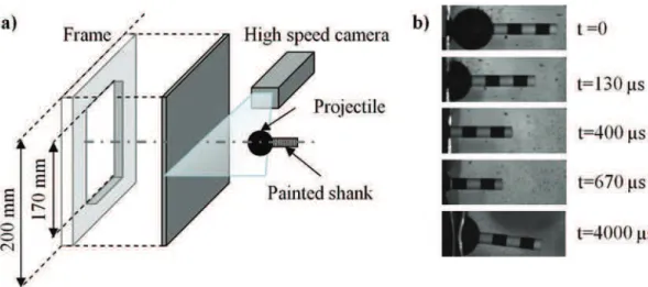
Normal impact tests are conducted using a gas gun. A spherical projectile of 127 g and 30 mm diameter is launched at an average velocity Viniof 120 m/s at the centre of the targets. The projectile is
composed by a hardened steel spherical nose and shank and is supposed perfectly rigid. The cylindrical shank with 8 mm diameter and 50 mm length is screwed to the rear of the nose. The same projectile is reused for all impact tests. A high speed camera is used to measure the projectile displacement and velocity during the test by following to the painted shank. Square targets of 200, 300 or 400-mm side are simply supported at the rear by a square frame with an aperture of 170-mm side (see Fig. 1). These boundary conditions are more representative of impact on real structures such as the aircraft fuselage compared to clamping along four edges. The experimental set-up and several camera pictures are given inFig. 1.
In the particular case of dry fabrics, the boundary conditions are defined in order to be representative of a real structure of about 600-mm side. During the impact, the primary yarns (i.e. the yarns situ-ated under the projectile) are loaded in tension, which induces a yarn elongation. The additional distance is called de-crimping length (seeFig. 2a and b). This distance can be calculated knowing the structure size and the weave properties. When considering the fabrics used in this study (cf.Table 1) the yarn crimp reaches 0.4% for the twill fabric and respectively 0.51% and 3.5% for the plain weave in the weft and warp direction. Therefore, the de-crimping length can reach 2.4 mm in the twill fabric and respectively 3.1 and 21 mm in the weft and warp direction of the plain fabric for a 600-mm side panel. In order to represent this mechanism with smaller samples comprised between 200 and 300-mm side, a free-edges boundary condition has been chosen. Thus, the yarns can potentially slide from the target extremity, providing an additional length under the impact point (Fig. 2c and d).
2.2. Material description and targets identification
The tested sandwich structures are assembled using aluminium or dry fabric front skins. Honeycomb core of different thicknesses
(from 10 to 30 mm) and materials (aluminium and Nomex) have been selected. Impact results on aluminium plates are used as reference cases. Among the wide choice of aluminium alloys, the 5XXX family alloys is chosen due to their ductile behaviour and their positive strain rate sensitivity which increases the skin resistance against the perforation [25]. More particularly, the AA5086-H111 aluminium alloy has been used as front and/or rear skin. Then, sandwich structures are assembled and tested using the same skin configurations, with the addition of aluminium honey-comb cores of several thicknesses. After that, dry fabrics are tested as a new front skin in sandwich structures.
The materials and structures used for the sandwiches assembly are described inTable 1.
The sample identification contains data about the front skin, the core and the rear skin respectively. Each material is associated with a letter (seeTable 1) and an index indicates the layer thickness or the number of plies (for fabric skins). A global index reports the target dimension (200, 300 or 400-mm side). For instance, a 200-mm side sandwich composed by a 12 plies of twill fabric as front skin, a 10-mm thick aluminium honeycomb and a 1-mm thick aluminium rear skin is noted [T12AH10A1]200. If a tested structure is
assembled without core, a synthetic notation is used: a 300-mm side aluminium target with a 2-mm thick front skin and a 1-mm thick rear skin is represented by [A2þ1]300.
Additional data are given concerning the sandwich assembly. Fabrics are assembled according to a quasi-isotropic stratification by combining plies oriented in 0/90"and #45" directions in the
following order: [0"/45"]
n, symwith n ¼ 2, 3, 4. These structures are
stitched in order to maintain the dry plies together. Therefore, a para-aramid filament is used (K-Tech 75, 0.23 mm diameter). The stitching pattern is a square grid of 10 or 20-mm side.
Skins and core are assembled using a Redux!
adhesive film. In the case of dry fabric front skin, the plies are stitched and then bonded to the core. Therefore, the last ply (ply in contact with the core) is totally impregnated with the Redux!
bond. 2.3. Impact results
The initial velocity presents dispersions due to the experimental set-up, so the value can be substantially different between the tested samples. However, the initial projectile velocity Vini is
measured from the camera pictures for each configuration, so the variability is known and taken into account in the analysis. The indexes Rfand Rrare respectively associated with the status of the
front and the rear skin after impact and are set to “N”, “C” or “Y” in case of non perforation, limit case and perforation. The residual projectile velocity Vresis measured after the end of contact between
the projectile and the target. Positive values of residual velocity indicate perforation while negative values are measured during the projectile rebound. The measure of Viniand Vresgives respectively
the initial kinetic energy of the projectile Einiand residual energy
Eres, which indicates the energy absorbed by the target Eabs. The
maximum projectile displacement dmaxand the residual
indenta-tion Iresare measured in non-perforated cases only. The maximum
projectile displacement is obtained from the camera pictures dur-ing the impact. The residual indentation is measured after impact by 3D correlation on the rear face of the rear skin. The weigh per unit surface
r
sis given for each configuration inTable 2.Fig. 2. a) Real structure e initial state; b) during impact; c) tested targets (free edges boundary condition) e initial state; d) during impact.
Table 1
Skins and cores representation and material data. Figure Name Description
At AA5086 aluminium plates (2700 kg/m3);
t ¼ 1 or 2 mm thick.
Ti Aramid twill fabric: 2/2 twill, 220 g/m2,
6.5 ends/cm. Twaron 2200 HM fibre (1620 dtex); number of plies i ¼ 8, 12 or 16. Pi Aramid plain weave fabric: 170 g/m2,
6.7 ends/cm. Twaron 2200 fibre (1210 dtex); number of plies i ¼ 12 or 18.
AHt Aluminium honeycomb (Hexcel): 30-mm
thick (3/8-5052-.004, 86.5 kg/m3), 20 mm
thick (ACG-3/8, 53 kg/m3), 10 mm thick
(ACG-1/4, 72 kg/m3)
NHt Nomex honeycomb (Hexcel): 20 mm
thick (HRH-78-1/8-3.0, 48 kg/m3)
3. Impact on aluminium sandwiches and core thickness influence
The study firstly focuses on “aluminium sandwiches”, i.e. aluminium skins with aluminium honeycomb core. Several sand-wich structures have been impacted varying the rear skin and the core thicknesses. The impact results are synthesized inTable 2for sandwich structures (group 2) and compared with aluminium plates (group 1).
3.1. Target size effect
The target dimensions are suspected to influence the impact results of both aluminium plates and sandwiches. Particularly, a significant difference is noticed between the 200 and 300-mm side samples. Deformed targets after impact are presented inFig. 3.
It can be shown fromFig. 3c that residual deformations reach the plate boundary in the case of 200-mm side sandwiches. A global bending effect of the structure and the target rotation at the vicinity of the support induce significant plate and core
deformations (which implies a greater amount of absorbed energy). The increase of target maximum indentation is also noticed: for instance, the [A2þ2]200 target is more indented than [A2þ1]400
despite a higher total thickness. It appears from these observations that 200-mm side targets behaviour is not representative of real structures. On the contrary, 300 and 400-mm side sandwiches are not deformed until the target size due to inertial effects which prevent the momentum of the structure near the boundary con-dition. Thus, 300 and 400-mm side targets results can be easily compared, but the comparison between 200 and 300-mm side samples is more delicate.
3.2. Damage mechanisms observations
The impact results on aluminium plates underline a limit rupture case for the [A2þ1]400target with a circular rupture at the rear of the
target, extended only to the 1-mm thick plate (seeFig. 4a and b). The [A2þ2]200target is not perforated but a necking zone can be clearly
seen near the impact point at the back of non-perforated samples (Fig. 4c). Aluminium plates in sandwich structures generally fail
Table 2
Structure configurations and impact results synthesis.
ID Figure rs[kg/m2] Vini[m/s] Rf/Rr Vres[m/s] Eabs[J]/% Eini dmax[mm] Imax[mm]
Group 1: aluminium plates
[A2þ1]400 8.19 124.4 N/C %22.4 951/96.8% 41.6 30.3
[A2þ2]200 10.9 126.6 N/N %9.3 1011/99% 31.9 31.7
Group 2: aluminium sandwiches
[A2AH10A2]200 11.8 120.0 N/N ea ea ea 24.7
[A2AH20A2(1)]200 12.0 122.5 C/N %6.3 949/99.5% 48.5 23.8
[A2AH20A2(2)]200 12.0 125.3 Y/Y 25.4 955/95.9% / /
[A2AH10A1]300 9.0 114.9 Y/Y 62.6 590/70.3% / /
[A2AH20A1]300 9.4 117.9 Y/Y 62.2 638/72.2% / /
Group 3a: dry fabric front skin sandwiches (200-mm side targets)
[T16AH10A2]200 10.2 123.2 N/N %12.0 955/99.1% 54.4 39.3
[T8AH10A2]200 8.3 126.0 C/Y 0.0 1199b/99.9% / /
Group 3b: dry fabric front skin sandwiches (300-mm side targets)
[T12AH30A1]300 8.4 115.2 N/N %3.0 843/99.9% 56.7 25.3
[P12AH30A1]300 8.0 123.8 N/N %5.8 971/99.8% 54.3 29.4
[P18NH20A1]300 7.5 114.4 N/N %12.9 821/98.7% 56.2 28.5 a Measure problem occurring during the test.
through plug initiation (Fig. 4b) and the formation of petals (Fig. 3b), which is a typical failure mode of ductile targets[26].
Two similar sandwiches namely [A2AH20A2(1)]200 and
[A2AH20A2(2)]200have been impacted at two different initial
veloc-ities, respectively 122.5 and 125.3 m/s. The first case [A2AH20A2(1)]200is identified as a limit case as only the front skin is
perforated (Fig. 5a). The second sample is totally perforated (Fig. 5b). Different damage mechanisms can be observed from re-sidual sandwich profiles shown inFig. 5. The [A2AH20A2(1)]200target
shows a 16-mm diameter circular rupture of front skin under the spherical nose and secondary cracks propagation resulting in petals formation. In the second case [A2AH20A2(2)]200, a circular cap of
18 mm diameter is formed and remains partially attached to the front skin. Honeycomb buckling is observed in both cases under the front skin and the honeycomb is totally crushed under the pro-jectile. In addition, out-of-plane shear deformations are observed in the core from the impact point to the target extremity. High out-of-plane skin deformations near the impact lead to a rupture of the bond between the core and the rear skin in a zone of 60 and 85 mm radius for [A2AH20A2(1)]200 and [A2AH20A2(2)]200 respectively (note
that in the second case the rear plate is almost separated from the rest of the target).
The [A2AH10A1]300and [A2AH20A1]300are totally perforated due
to the target size increase (from 200 to 300-mm side) and the rear plate thickness decrease (from 2 to 1-mm thick). However the corresponding reference of aluminium plates [A2þ1]400is not totally
perforated (limit case of aluminium plates alone).
3.3. Influence of core in aluminium sandwich structures subjected to impact
As for as the projectile evolution of the reference case [A2þ2]200,
a change can be observed in the slope from about 0.4 ms after the
onset of impact and the projectile braking is decreasing after this limit. A previous study on aluminium plates showed that the first stage is attributed to the local indentation of the plates and the second is due to a structural effect (see Fig. 7). This behaviour consists in a global bending of the target in the same direction than the projectile (which explains the decrease of projectile braking) and occurs when the deformations in the plates reach the boundary condition (see Figs.7 and 8a). This mechanism leads to a large amount of absorbed energy. It is not or partially seen in perforated cases, depending on the front skin rupture apparition in the impact sequence.
The sandwich structures appear to brake the projectile less efficiently than the skins configuration, as shown inFig. 6a (gap of about 15 m/s from 0.16 ms impact duration between [A2þ2]200and
[A2AH20A2(1)]200). However, the skins configuration [A2þ2]200 is
more indented than the sandwich structures as shown inFig. 6b (þ27% and þ41% indentation compared to respectively [A2AH20A2(1)]200 and [A2AH10A2]200). The [A2AH20A2(1)]200 and
[A2AH10A2]200residual profiles are very close and show a double
curvature, global and local as described in Refs.[19e22]. However, the front skin local curvature appears to be larger in the sandwich configuration than in the skins alone, which is probably due to the radial sliding of the honeycomb providing a gap between the two skins (see Figs. 5a and b, and 6b as well as the corresponding scheme inFig. 8b and c).
In the sandwich structure, a partial de-coupling occurs due to the separation of the two skins. It consists in a deformation of the front skin alone, followed by the reaction of both skins together (see
Fig. 8b). This case corresponds typically to the [A2AH10A2]200
configuration where no skins rupture occurs and the plastic de-formations reach the boundary condition for both skins (seeFig. 5c). In a virtual sandwich configuration with a very thick core, it could be envisaged that the front skin fails before the contact be-tween both skins and the rear skin deformation (as illustrated in
Fig. 7c). In this case, the two skins would react simultaneously, resulting in a decrease of the energy absorption in the target, (no structural effect occurring and earlier rupture initiation) and thus higher residual velocities of the projectile. Both [A2AH20A2(1)]200and
[A2AH20A2(2)]200configurations are intermediate cases between the
partial and total de-coupling shown inFig. 8b and c. The projectile velocity evolution is similar for these two configurations until 0.34 ms. After this moment, the two curves gradually differ, resulting in a negative residual velocity in the first case (projectile rebound) and a positive value (target perforation) in the second case. Considering the experimental data available, no explanation can be given to justify the difference in the velocity evolution be-tween the [A2AH20A2(1)]200and the [A2AH20A2(2)]200cases on the one
hand, and between these sandwich and the [A2þ2]200skins on the
other hand. However, a potential scenario can be proposed. Considering that the front skin local curvature and deformation (depending on the core height as shown inFig. 6b) is higher in the sandwich structure, the onset of rupture may appear earlier in the sandwich than in the plates (and probably before the contact of the two skins as shown inFig. 8c). Therefore, the rupture initiation and propagation in the front skin sandwich structure could be the explanation for the first divergence between the skins and the sandwich cases, occurring after 0.2 ms.
4. Impact of sandwiches with dry fabric skins
A preliminary study of the front skin choice in the sandwich impact resistance has been conducted. Dry stitched fabrics, com-posite skins and aluminium skins have been tested as front skin in several sandwich structures. The composite front skin sandwiches were systematically perforated, for a similar or superior weight Fig. 3. [A2AH20A1]300 target: a) front view; b) rear view; c) front view of
than aluminium skins. This result is attributed to the fibre-matrix adhesion which stops the relative move of the yarns and results in a stiff but fragile behaviour. Moreover, the front skin damage remains local which implies a decrease of energy absorption. On the contrary, the dry front skin samples were not perforated despite a lower area density than the impregnated cases and no fibre rupture has been observed. This result shows that the use of dry fabric skins is more advantageous than composites in medium-velocity impacts.
Thus, several sandwich structures with dry fabrics front skin and aluminium honeycomb and rear plates are tested and compared in this section. Several parameters are studied: target size, number of plies, weave pattern (twill and plain) and core characteristics (thickness and properties). The impact results of dry fabric front skin structures are synthesized inTable 2(group 3).
4.1. Damage mechanisms observation of group 3a targets
The [T8AH10A2]200target composed by 8 dry fabric plies as front
skin is the only perforated case of the group 3. Note that the same structure with 16 dry fabric plies is not perforated. Yarn sliding appears to be one of the most significant damage mechanisms for the first plies. A cross shape sliding is noticed for the primary yarns, i.e. yarns situated directly under the projectile. The observed damage are represented by a scheme inFig. 9for 0/90"and #45"
oriented plies and the example of [T8AH10A2]200is given inFig. 10a.
In this case, yarn sliding is visible from the target boundary to the impact location. Note that the sliding distance is very similar be-tween the weft and the warp direction for twill and plain fabrics. Fig. 4. [A2þ1]400target: a) front skin; b) rear skin; c) rear skin of the [A2þ2]200sample.
Fig. 5. Residual profiles of different targets: a) [A2AH20A2(1)]200; b) [A2AH20A2(2)]200; c)
In order to obtain a better understanding of the energy ab-sorption mechanisms in dry fabric skins, damage mechanisms of each ply have been observed after impact.
The average sliding distance of the primary yarns reach respectively 140, 70 and 20 mm for the first 0/90"oriented plies
(plies n"1, 3 and 5 respectively) and 45 and 0 mm for the #45"
oriented layers (plies n"2, 4). These yarns are visible inFig. 10b at
the rear of the target and form a pocket which stopped the pro-jectile. The difference of sliding distance between 0/90"oriented
layers and #45"layers can be associated with the superior yarn
length and the yarn crossing increase.
From the 6th layer, no yarn sliding is observed. The stitched points vicinities are partially impregnated with resin due to the adhesive film used to bond the core and the rear of the fabric skin (seeFig. 10c). Moreover, yarn and matrix ruptures can be noticed near the impact location. As a result, considering that the resin impregnation highly influences the fabric properties and impact performances (as shown in the introduction of Section4), only the 5 first layers have to be considered as dry fabrics.
In addition to principal yarn sliding, other damage mechanisms can be observed in the front skin. Firstly, no yarn rupture is observed in dry plies. It is due to the free edges boundary condi-tions and the possibility for yarns to slide instead of break. Fig. 6. Aluminium sandwiches targets: a) projectile velocity; b) residual profiles.
Fig. 7. Local and global deformation in a sandwich structure during the impact[27].
However, stitching points are broken around the impact point in a zone of approximately 60 mm radius. This rupture may be associ-ated with high out-of-plane deformations of the initial woven pattern near the impact (see Fig. 9a). However, the partial impregnation of the stitch points near the 6th ply which is also a possible cause of stitching rupture.
The same damage mechanisms than those described in Section
3are observed in the core and the rear skin of the sandwich: partial cap formation of the aluminium rear skin (Fig. 10b), secondary cracks, honeycomb crushing and adhesive bond rupture between the core and the rear skin at the impact vicinity. Several energy absorption mechanisms can be identified from the [T8AH10A2]200
target. Firstly, the wide plastic deformations of the rear skin, extended from the impact location to the boundary condition as well as the plate rupture are associated with significant energy absorption. The part of energy absorbed in the core is supposed to be low because of the limited zone concerned. Several potential energy absorption mechanisms in dry fabrics can be identified. The most significant one may be associated with frictional contact properties between the yarns through several contacts: weft/warp yarn crossings, contacts between the plies and between the pro-jectile and the first ply[22].
Note that the primary yarns sliding of [T8AH10A2]200is superior
to the maximum allowable sliding displacement defined in Section
2.1, set to 12 mm for a twill weave. Therefore, the free-edges boundary conditions chosen for 200-mm side configurations in-fluence the target performances. The experimental test conducted on 200-mm side target is less critical than a real case by allowing a longer yarn sliding distance. Thus, further tests have been con-ducted on bigger sandwich structures of 300-mm side to be more representative of the real case.
4.2. Damage mechanisms observation of group 3b targets
On the contrary to aluminium sandwiches, none of the 300-mm side sandwiches with dry fabric skins are perforated (Table 2). The primary yarn sliding distance is measured from the samples after impact. The average values reach respectively 10 and 13.8 mm (Fig. 11d) for plain and twill woven pattern, which is in the allow-able range considering the boundary conditions hypothesis (see Section2.1).
The target observation ofFig. 11a and b shows highly deformed folds from the impact point to the target extremity. They are initiated from the last impregnated ply (the 8th ply which is in contact with the core) which is highly deformed. In these zones, a local debonding of the adhesive film is observed between the fabric skin and the core. The folds are more pronounced for plain than for twill weave because of the higher stiffness of the plain woven pattern. Note that they are not visible in the 200-mm side targets due to a global bending deformation of the structures. The aluminium honeycomb located under the front skin is highly deformed in compression under the projectile, with a partial densification at the vicinity of impact (Fig. 11c). Moreover, a rupture of the adhesive bond assembling the honeycomb cells is visible near the support, showing high in-plane traction solicitations. The previous observations are directly relied to the target dimension, as for aluminium sandwich structures. Indeed, in 300-mm side Fig. 9. Damage of fabrics: a) in 0/90"plies; b) in #45"plies.
Fig. 10. [T8AH10A2]200sandwich after impact: a) ply n"1 of the front skin; b) side view;
samples, no global bending is observed due to inertial effects, contrary to 200-mm side targets for which a rotation appears near the boundary condition. Therefore, the damage observed in 300-mm side targets are out-of-plane compression and shear in a localized zone instead of global structure bending for 200-mm side samples.
It seemed interesting to assembly Nomex instead of aluminium honeycomb with dry fabrics in order to reduce the target weight. Thus, a 20 mm-thick Nomex honeycomb core has been tested with 18 plies of dry fabrics as a front skin. The weight per unit area reaches 7.5 kg/m2compared to 8 kg/m2with the aluminium hon-eycomb structure and only 12 plies of aramid fabrics. Several views of the target after impact are seen in Fig. 12. Note that the compressive damage in Nomex honeycomb is visible in a large area around the impact location, contrary to the localized buckling and de-bonding of the aluminium honeycomb cells shown inFig. 11c. Moreover, this configuration is less indented than the [P12AH30A1]300configuration, probably due to the increase in fabric
plies and thus in the transverse rigidity of the front skin. 4.3. Impact results of dry fabric skins
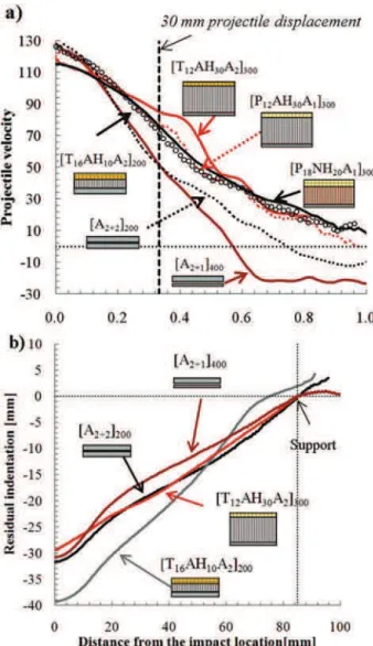
The velocity curves seen inFig. 13a show the evolution of non-perforated sandwiches as well as corresponding aluminium refer-ence cases ([A2þ2]200 and [A2þ1]400). In comparison with the
[A2þ2]200aluminium skin configuration of the same dimensions, it
can be noticed that the projectile braking decreases with the use of dry fabric front skin, especially at the onset of impact. This may be associated with the very low out-of-plane stiffness of the fabric front skin and the time needed to initiate the fabric reaction and damage: yarn stretching, woven pattern deformation, primary yarns sliding, etc. Note that similarly to aluminium sandwiches, structural effects can be observed from the velocity curves of dry fabric front skin sandwiches. However, the slope change is not pronounced and appears from about 0.5 ms.
Fig. 11. Front views of: a) [T12AH30A1]300target; b) [P12AH30A1]300target; c) honeycomb damage of [T12AH30A1]300; d) sliding distance of primary yarns of [T12AH30A1]300.
The behaviour during the impact sequence is very close when comparing the targets with twill or plain weaves. Several fluctua-tions can be noticed from the velocity curve of the [T12AH30A1]300
target, which are less pronounced for the same configuration with plain fabric. This behaviour is may be due to the rupture of the honeycomb cells bond near the support, as shown inFig. 11c. This damage is also observed to a lesser extend in the plain fabric front
skin sandwich, which results in a smoother curve. Note that this phenomenon is not observed in the case of 200-mm side targets, because of the global bending deformation.
The residual indentation given inFig. 13b is measured from the rear skin profiles for several configurations. Concerning residual indentation of 200-mm side targets, the low out-of-plane stiffness of dry fabrics and the target dimensions leads to a significant increase of target indentation, as shown inFig.13b (24% of maximum indentation for [T16AH10A2]200compared to the [A2þ2]200aluminium
configura-tion). Similarly to aluminium sandwiches, the target dimension decrease induces global bending deformation of the target corre-sponding to an increase of residual indentation. However, the 300-mm side configurations are less indented than aluminium plates alone due to the core thickness increase: %3%, %5.9% and %16.5% of indentation for respectively [P12AH30A1]300, [P18NH20A1]300 and
[T12AH30A1]300compared to [A2þ1]400.
5. Structures comparison and discussion
The targets can be compared from the point of view of the per-formance criteria evoked in Section1: no perforation with minimal weight and back deformation. Several non-perforated structures are compared considering the energy reported to the weight per unit area or the energy reported to the maximum indentation (seeFig.14). Note that the ratios are calculated using the initial kinetic energy and not the absorbed energy due to initial velocity dispersions of the projectile. Thus, the ratios given inFig. 14have to be considered as lower limits of the targets, except for the [A2AH20A2(1)]200and the
[A2þ1]400targets, which are limit cases of perforation.
The best configurations identified in terms of kinetic energy per weight per unit surface are [P18NH20A1]300 and [P12AH30A1]300.
These structures clearly outperform aluminium plates and sand-wiches like [A2þ1]400and [A2AH20A2(1)]200as they are limit cases of
rupture. However, the complexity of the structure studied (wide choice of material and geometrical parameters choice), as well as the lack of experimental data in dynamic tests are strong limita-tions to properly explain these results. Moreover, the literature rarely addresses studies on ply fabric structures or multi-material targets, so that the influence of coupling or structural ef-fects is not known. One can only say that the energy dissipation mechanisms in dry fabrics and aluminium front skins are clearly different. In the tested impact conditions, the rupture of the front or rear aluminium skin is often observed whereas the dry fabric front skin “failed” only in one configuration (yarn sliding without rupture). Thus, the perforation resistance of this type of skin ap-pears to be higher than those of aluminium plates which could partially explain the better results of the associated sandwich configurations.
Fig. 13. a) Projectile velocity evolution during impact; b) residual profile after impact for Groups 1 and 3.
Concerning the aluminium plates, the presence of aluminium honeycomb core is not advantageous in terms of weight and resistance against perforation (see [A2AH20A2(1)]200and [A2þ2]200).
Configurations using twill fabrics are less interesting than plain fabric structures due to their substantial weight per unit surface (respectively 220 g/m2and 170 g/m2for twill and plain weaves). The increase of core thickness induced a slight increase of the target weight, which is largely balanced by a possible decrease of the fabric ply number without perforating (see the comparison be-tween [T16AH10A2]200and [T12AH30A1]300).
The structures can be also compared with the criterion of kinetic energy reported to the target indentation. Fig. 14b compares the structures performances for non-perforated 300-mm side targets. It can be seen that the results are very close between the selected structures: criterion comprised between 31.5 and 33.5. The sand-wich configurations outperform the aluminium skins. Indeed, the target indentation decreases with the increase of core thickness, which is a global tendency observed for both dry fabrics and aluminium front skins.
6. Conclusion
An experimental study has been conducted in order to identify potential solutions of sandwich structures subjected to impacts. Several points have to be underlined:
1. The front skin choice is very important for the target perfora-tion resistance. Aluminium and dry fabric are potential candi-dates and have been tested in this study as front skin. 2. The target dimension influences the impact performances.
300-mm side targets are representative of real structures but this is not the case of 200-mm side samples: deformations of the target edges and momentum of the target near the support.
Concerning aluminium sandwiches, i.e. aluminium skins with aluminium honeycomb core:
3. Non-perforated cases of sandwich structures are less indented than aluminium skins alone.
4. It appears from the experiments that the sandwich structures have a lower resistance against the perforation, compared to the associated skins configurations. As an example, a limit of perforation is obtained with a 200-mm side sandwich with a 20 mm thick honeycomb core impacted at 950 J, while the same configuration with aluminium skins alone is not perfo-rated. The experimental data available is not sufficient in establishing possible impact scenarii to explain these results. However, a hypothese based on the possible link between the core thickness, skins de-coupling and the onset of rupture in the front skin is proposed in this paper.
Concerning dry fabric front skin sandwiches:
5. Dry fabrics give better impact results than fabrics impregnated with resin. The resin provides an increase of rigidity of the skin and fails locally under the projectile under out-of-plane shear solicitation. This leads to the rupture of the total structure. To solve the problem of fabrics assembling, several dry fabrics are thus assembled by stitching.
6. Free-edges boundary conditions have been chosen for dry fabric skins samples to reproduce the potential de-crimping length of a real clamped structure.
7. Dry fabric front skin sandwiches show a good perforation resistance compared to aluminium sandwiches or plates, with
a comparable or lower total weight and indentation, especially for 300-mm side configurations.
8. No yarn rupture is observed in dry fabric structures. Several mechanisms susceptible to dissipate the projectile energy are identified: primary yarns sliding, in-plane deformations of the initial woven pattern, frictional effects (contacts between weft/ warp yarns, between plies and between the first ply and the projectile), deformation and yarn rupture of partially resin impregnated plies, etc.
9. A configuration of sandwich structure using Nomex instead of aluminium honeycomb has been tested. The target showed good impact performance, with a decreasing weight and back indentation without perforating.
Acknowledgement
The authors want to thank the National Research Agency for the financial support through the MANSART Project based on saNd-wichS ARchitecTured MAterials.
References
[1]Rathbun HJ, Radford DD, Xue Z, He MY, Yang J, Deshpande V, et al. Perfor-mance of metallic honeycomb-core sandwich beams under shock loading. Int J Solids Struct 2006;43:1746e63.
[2]Dharmasena KP, Wadley HNG, Xue Z, Hutchinson JW. Mechanical response of metallic honeycomb sandwich panel structures to high-intensity dynamic loading. Int J Impact Eng 2008;35:1063e74.
[3]Goldsmith W, Wang G, Li K, Crane D. Perforation of cellular sandwich plates. Int J Impact Eng 1997;19(5e6):361e79.
[4]Børvik T, Clausen AH, Hopperstad OS, Langseth M. Perforation of AA5083-H116 aluminium plates with conical-nose steel projectiles e experimental study. Int J Impact Eng 2004;30:367e84.
[5]Teng X, Wierzbicki T, Huang M. Ballistic resistance of double-layered armour plates. Int J Impact Eng 2008;35:870e84.
[6]Iqbal MA, Gupta NK. Energy absorption characteristics of aluminium plates subjected to projectile impact. Lat Am J Solids Stru 2008;5:259e87. [7]Corran RSJ, Shadbolt PJ, Ruiz C. Impact loading of platesan experimental
investigation. Int J Impact Eng 1983;1:3e22.
[8]Teng X, Dey S, Børvik T, Wierzbicki T. Protection performance of double-layered metal shields against projectile impact. J Mech Mater Solids 2007;2: 1307e28.
[9]Dey S, Børvik T, Teng X, Wierzbicki T, Hopperstad OS. On the ballistic resis-tance of double-layered steel plates: an experimental and numerical investi-gation. Int J Solids Struct 2007;44:6701e23.
[10] Marrom I, Bodner SR. Projectile perforation of multi-layered beams. Int J Mech Sci 1979;21:489e504.
[11] Radin J, Goldsmith W. Normal projectile penetration and perforation of layered targets. Int J Impact Eng 1988;7:229e59.
[12] Cheeseman BA, Bogetti TA. Ballistic impact into fabric and compliant com-posite laminates. Compos Struct 2003;61:161e73.
[13] Cunniff PM. An analysis of the system effects of woven fabrics under ballistic impact. Text Res J 1992;62(9):495e509.
[14] Zeng XS, Shim VPW, Tan VBC. Influence of boundary conditions on the bal-listic performance of high-strength fabric targets. Int J Impact Eng 2005;32: 631e42.
[15] Chitrangad. Hybrid ballistic fabric. United States Patent No.5,187,003, 16 February 1993.
[16] Briscoe BJ, Motamedi F. The ballistic impact characteristics of aramid fabrics: the influence of interface friction. Wear 1992;158(1e2):229e47.
[17] Karahan M, Kus A, Eren R. An investigation into ballistic performance and energy absorption capabilities of woven aramid fabrics. Int J Impact Eng 2008;35:499e510.
[18] Ahmad MR, Ahmad WYW, Salleh J, Samsuri A. Effect of fabric stitching on ballistic impact resistance of natural rubber coated fabric systems. Mater Des 2008;29:1353e8.
[19] Federal Aviation Administration. Review of damage tolerance for composite sandwich airframe structures 1999.
[20] Anderson T, Madenci E. Experimental investigation of low-velocity impact characteristics of sandwich composites. Compos Struct 2000;50:239e47. [21] Schubel PM, Luo JJ, Daniel IM. Low velocity impact behavior of composite
sandwich panels. Compos Part A 2005;36:1389e96.
[22] Choi IH. Contact force history analysis of composite sandwich plates subjected to low-velocity impact. Compos Struct 2006;75(1e4):582e6.
[23] Abrate S. Localized impact on sandwich structures with laminated facings. Appl Mech Rev 1997;50(2):69e82.
[24] Buitrago BL, Santiuste C, Sánchez-Sáez S, Barbero E, Navarro C. Modelling of composite sandwich structures with honeycomb core subjected to high-velocity impact. Compos Struct 2010;92(9):2090e6.
[25] Clausen AH, Børvik T, Hopperstad OS, Benallal A. Flow and fracture charac-teristics of aluminium alloy AA5083-H116 as function of strain rate, tem-perature and triaxiality. Mat Sci Eng A Struct 2004;A364:260e72.
[26] Gupta NK, Iqbal MA, Sekhon GS. Effect of projectile nose shape, impact ve-locity and target thickness on deformation behavior of aluminum plates. Int J Solids Struct 2007;44:3411e39.
[27] Hoo Fatt MS, Sirivolu D. A wave propagation model for the high velocity impact response of a composite sandwich panel. Int J Impact Eng 2010;37: 117e30.
![Fig. 5. Residual pro fi les of different targets: a) [A 2 AH 20 A 2 (1) ] 200 ; b) [A 2 AH 20 A 2 (2) ] 200 ; c) [A 2 AH 10 A 2 ] 200 .](https://thumb-eu.123doks.com/thumbv2/123doknet/12305802.324359/8.892.197.697.127.645/fig-residual-pro-fi-les-different-targets-ah.webp)
![Fig. 7. Local and global deformation in a sandwich structure during the impact [27].](https://thumb-eu.123doks.com/thumbv2/123doknet/12305802.324359/9.892.67.404.138.712/fig-local-global-deformation-sandwich-structure-impact.webp)
![Fig. 10. [T 8 AH 10 A 2 ] 200 sandwich after impact: a) ply n " 1 of the front skin; b) side view;](https://thumb-eu.123doks.com/thumbv2/123doknet/12305802.324359/10.892.477.823.129.691/fig-t-ah-sandwich-impact-ply-skin-view.webp)
![Fig. 11. Front views of: a) [T 12 AH 30 A 1 ] 300 target; b) [P 12 AH 30 A 1 ] 300 target; c) honeycomb damage of [T 12 AH 30 A 1 ] 300 ; d) sliding distance of primary yarns of [T 12 AH 30 A 1 ] 300 .](https://thumb-eu.123doks.com/thumbv2/123doknet/12305802.324359/11.892.164.711.137.530/views-target-target-honeycomb-damage-sliding-distance-primary.webp)