HAL Id: hal-01009071
https://hal.archives-ouvertes.fr/hal-01009071
Submitted on 29 Oct 2018HAL is a multi-disciplinary open access archive for the deposit and dissemination of sci-entific research documents, whether they are pub-lished or not. The documents may come from
L’archive ouverte pluridisciplinaire HAL, est destinée au dépôt et à la diffusion de documents scientifiques de niveau recherche, publiés ou non, émanant des établissements d’enseignement et de
Two new limit analysis mechanisms for the computation
of the collapse pressures of circular tunnels driven by a
pressurized shield
Guilhem Mollon, Daniel Dias, Abdul-Hamid Soubra
To cite this version:
Guilhem Mollon, Daniel Dias, Abdul-Hamid Soubra. Two new limit analysis mechanisms for the com-putation of the collapse pressures of circular tunnels driven by a pressurized shield. 2nd International Conference on Computational Methods in Tunneling (EURO:TUN 2009), 2009, Bochum, Germany. �hal-01009071�
Two new limit analysis mechanisms for the computation of
the collapse pressures of circular tunnels driven by a
pressurized shield
Guilhem MOLLON1, Daniel DIAS2 and Abdul-Hamid SOUBRA3 1
PhD Student, INSA Lyon, Université de Lyon, LGCIE Domaine B, 69621 Villeurbanne Cedex, France. E-mail: guilhem.mollon@gmail.com,
2
Associate Professor, INSA Lyon, Université de Lyon, LGCIE Domaine B, 69621 Villeurbanne Cedex, France. E-mail: daniel.dias@insa-lyon.fr,
3
Professor, University of Nantes, Civil Engineering Department, Bd. de l’université, BP 152, 44603 Saint-Nazaire cedex, France. E-mail: abed.soubra@univ-nantes.fr
Abstract
This paper focuses on the computation of the tunnel face collapse pressure of a shallow circular tunnel driven by a pressurized shield. This allows one to assess the necessary pressure to apply to the tunnel face in order to ensure its stability against collapse. Two new three-dimensional failure mechanisms based on the upper bound limit analysis theorem are proposed. The first failure mechanism is an improvement of the two-block collapse mechanism presented by Leca and Dormieux [1]. It is composed of several truncated rigid cones. The second mechanism (derived from the previous one) has the advantage to consider the whole circular face of the tunnel instead of an inscribed vertical ellipse as is the case of previous mechanisms [1]. This makes the generation of the second mechanism much more complex than the first one because one can not use simple geometrical shapes such as cones. The resulting collapse pressures provided by the proposed mechanisms are presented and discussed.
Keywords: Limit analysis, pressurized shield, active failure, collapse pressure, failure
1 INTRODUCTION
The aim of the stability analysis of tunnels driven by a pressurized shield is to ensure safety against soil collapse in front of the tunnel face. This requires the determination of the minimal fluid pressure (i.e. air pressure in the present paper) required to prevent this collapse. The kinematical limit analysis model by Leca and Dormieux [1] is one of the most recent and significant approaches. It uses the upper-bound theorem of limit analysis. This theorem states that if a work calculation is performed for a kinematically admissible collapse mechanism, then the loads thus deduced will be higher than (or equal to) those for collapse. Since the tunnel face pressure resists the collapse of soil into the tunnel, it is a negative load in the sense discussed above. The kinematical approach will therefore provide a lower-bound unsafe estimate of the tunnel pressure required to maintain stability (i.e. smaller or equal to that actually required). The aim of this paper is to improve the best (i.e. the greatest) existing lower-bound solutions given by [1] using the kinematic theorem of the limit analysis theory. The soil considered in the analysis is assumed to be frictional (with or without cohesion). The problem of computation of the tunnel face collapse pressure σc can be idealized as shown
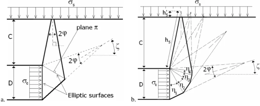
in Fig. 1 by considering a circular rigid tunnel of diameter D driven under a depth of cover C. Active collapse of the tunnel is triggered by application of surcharge σs and self-weight, with the tunnel face pressure σc providing resistance against
failure. The collapse mechanism presented in [1] (Fig. 1a) provides the best existing lower bound of σc. It is composed of two truncated conical blocks in
translation with opening angles equal to 2φ in order to respect the normality condition in limit analysis. It is entirely defined by only one angular parameter. In the following sections, one presents two new three-dimensional failure mechanisms based on the upper bound limit analysis theorem. This is followed by presentation and discussions of the numerical results given by both mechanisms.
2 MULTIBLOCK MECHANISM
The first proposed failure mechanism, called here “multiblock mechanism”, is described in more details in Mollon et al. [2]. It is an improvement of the two-block collapse mechanism presented in [1]. This mechanism is composed of n truncated rigid cones with circular cross-sections and with opening angles equal to 2φ. A mechanism with n=5 is presented in Fig. 1b. The geometrical construction of this mechanism is similar to that of Leca and Dormieux [1], i.e. each cone is the mirror image of the adjacent cone with respect to the plane that is
normal to the contact surface separating these cones. This is a necessary condition to ensure the same elliptical contact area between adjacent cones. As for the mechanism by Leca and Dormieux [1], block 1 is a truncated circular cone adjacent to the tunnel face. The intersection of this truncated cone with the tunnel face is an elliptical surface inscribed in the tunnel face. On the other hand, block 1 is truncated with a plane which is inclined at an angle
η
1 with the vertical direction. The multiblock mechanism is completely defined by n angular parameters ζ and ηi (i=1…n-1) where n is the number of the truncated conicalblocks (Fig. 1b). The upper rigid cone will or will not intersect the ground surface depending on φ and C/D values.
a. b.
Figure 1: a. Leca-Dormieux mechanism ; b. Multiblock mechanism
3 IMPROVED MULTIBLOCK MECHANISM
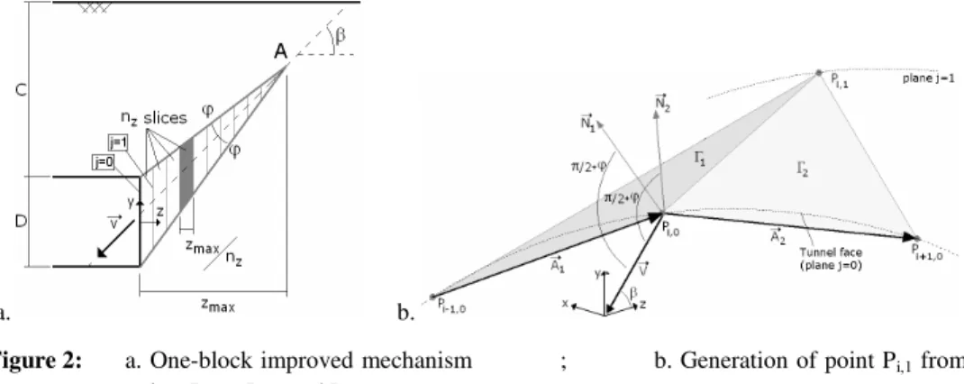
The main shortcoming of the proposed multiblock mechanism is that the circular tunnel face is not entirely taken into account in the assessment of the collapse pressure. To solve this problem, a so-called “improved multiblock mechanism” is considered herein. Firstly, an ‘improved one-block mechanism’ is presented. It is followed by the presentation of the ‘improved multiblock mechanism’. The improved one-block mechanism considers the whole tunnel face. It is defined by a single angular parameter β (Fig. 2a). This angle corresponds to the inclination of the velocity of this block with respect to the longitudinal axis of the tunnel. Since a failure mechanism involving the whole circular area of the tunnel face is explored here, no simple geometrical shape (such as a cone) can be considered. It
is necessary to generate the three-dimensional failure surface “point by point” using a spatial discretisation technique. It is assumed (Fig. 2a) that the cross-section of the improved one-block mechanism in the vertical plane containing the longitudinal axis of the tunnel is the same as that of the one-block mechanism composed of a single conical block with an opening angle equal to 2φ. This is to be expected because the conical one-block mechanism involves the entire diameter of the tunnel face only along the vertical diameter of the tunnel face.
a. b.
Figure 2: a. One-block improved mechanism ; b. Generation of point Pi,1 from points Pi-1,0, Pi,0, and Pi+1,0
The three-dimensional failure surface of the improved one-block mechanism is determined here by defining the contours of this surface at nz several equidistant
vertical planes parallel to the tunnel face (Fig. 2a). The contour in a given plane being defined from that in the preceding plane. The first vertical plane to be considered is that of the tunnel face for which the contour of the failure surface is circular as required. The vertical planes are denoted by index j where j=0, …, nz;
j=0 being that of the tunnel face (cf. Fig.2a). The contour of the tunnel face is discretised by a number nθ of points Pi,0 uniformly distributed along this contour.
Thus, each point of the failure surface is defined by two indices i (index indicating the position of the point in a given vertical plane) and j (index of the vertical plane). The generation of point Pi,1 in the first contour makes use of three
points Pi,0, Pi-1,0, and Pi+1,0 belonging to the tunnel face (Fig. 2b). The position of
point Pi,1 must satisfy the three following conditions:
• Pi,1 belongs to plane j=1
• The triangular surface formed by points Pi,0, Pi-1,0, and Pi,1 should respect
the normality condition in limit analysis, i.e. the normal to the plane of this triangle should make an angle
π
2
+
ϕ
with the velocity vectorV
r
This normality condition is necessary for the failure mechanism to be kinematically admissible.
• The triangular surface formed by points Pi,0, Pi+1,0, and Pi,1 should also
respect the normality condition.
The procedure described above allows one to create for each point Pi,j a
corresponding point Pi,j+1 in the following plane by respecting the normality
condition around Pi,j. This procedure should be repeated for all the nθ points of
the tunnel face to generate the corresponding nθ points in the plane j=1. Once the
first contour is generated, the same procedure is again applied to generate the points of the plane j=2 from those of plane j=1, and so on up to the plane j=nz.
The detailed mathematical formulation of this problem can be found in [3].
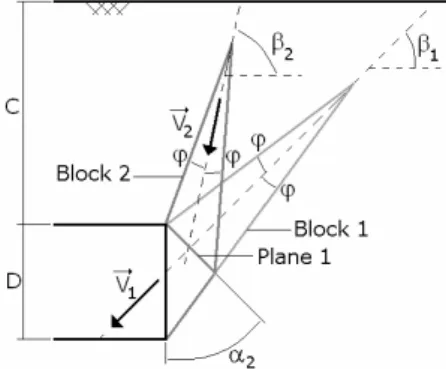
Figure 3: Generation of a second block
The improved one-block mechanism described before does not offer a great degree of freedom since it is characterized by only one angular parameter. In order to get better lower-bound solutions of the collapse pressure, the one-block mechanism is generalised to a multiblock mechanism by increasing the number of blocks. As mentioned before, the failure surface of the improved one-block mechanism was generated from the circular tunnel face, but it can also be generated from any arbitrarily section since the surface is generated from the discretised contour of the tunnel face and not from its analytical expression. Consequently, it is possible to add a second block above the first block (Fig. 3). Thus, the first block called ‘block 1’ adjacent to the tunnel face is truncated with a plane named ‘Plane 1’ inclined at an angle α2 with the vertical direction. The area
generate the second block called ‘block 2’ whose axis is inclined at β2 with the
horizontal direction. The intersection points between block 1 and plane 1 are used for the generation of the second block using exactly the same equations as those for the first block except the fact that these equations are now used in the local axes related to the contact plane separating both blocks. The geometrical procedure of construction of an additional block described above is successively applied to generate the multi-block mechanism. This mechanism is entirely defined by the 2n-1 as yet unspecified angular parameters αk (k=2,…, n) and βl
(l=1, …, n) where n is the number of blocks of the failure mechanism.
4 WORK EQUATION
For both the multiblock and the improved multiblock mechanisms, the work equation is written here for a frictional and cohesive soil. The velocity of each block is determined by the condition that the relative velocity between the blocks in contact has the direction that makes an angle φ with the contact surface. The determination of the different velocities, volumes and lateral surfaces of the truncated rigid blocks together with the computation of the different rates of work of external forces are detailed in [2] for the multiblock and [3] for the improved multiblock. Notice that the external forces involved in the present mechanisms are the weights of the different truncated rigid blocks, the surcharge loading acting on the ground surface (only in case of outcrop of the mechanism) and the collapse pressure of the tunnel face. Since no general plastic deformation of the truncated blocks is permitted to occur, the rate of internal energy dissipation takes place only along the different velocity discontinuity surfaces. After some simplifications, it is found that a lower-bound on the tunnel collapse pressure is:
c DNγ cNc sNs
σ
=γ
− +σ
(1)where Nγ, Nc, and Ns are non-dimensional coefficients (which are different in the
case of a multiblock or an improved multiblock mechanism). These coefficients and consequently σc, depend not only on the mechanical and geometrical
characteristics c, φ, and C/D, but also on the angular parameters of the failure mechanism considered in the analysis. The critical tunnel collapse pressure is obtained by maximization of σc given by Eq. (1) with respect to these angular
parameters. A number of five (resp. three) blocks was found to be a good compromise between accuracy and computation time for the multiblock (resp. improved multiblock) mechanism. The CPU time necessary for the calculation of
the collapse pressure is negligible for the multiblock mechanism and is about 5 to 10 minutes for the improved multiblock mechanism on a 2.4 GHz quad-core CPU.
5 NUMERICAL RESULTS
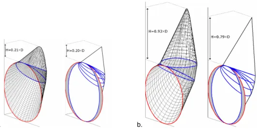
The lower-bound solutions of the tunnel face collapse pressure as determined by Leca and Dormieux (1990), by the multiblock mechanism and by the improved multiblock mechanism are given in Fig. 4 for two cases of a cohesionless soil, and for two cases of a frictional and cohesive soil (soft and stiff clays). One can see that the improvement (i.e. increase of the collapse pressure) of the multiblock and improved multiblock mechanisms attains 7% and 19% respectively with respect to the solution by Leca and Dormieux (1990) for a sand with φ=20°. This improvement becomes equal to 24% and 44% respectively for the soft clay, and attains 50% and 89% respectively for the stiff clay. Fig. 5 shows a comparison between the critical failure mechanisms given by the multiblock and by the improved multiblock mechanism in two different cases: (a) a cohesionless soil with φ=30° and C/D>0.5 and (b) a soft clay with φ=17°, c=7kPa, and C/D>0.8. One can see that the critical failure mechanisms given by both approaches are quite similar. Notice however that the multiblock mechanism does not intersect the whole tunnel face, the grey part of the tunnel face being at rest. This phenomenon is striking and was removed in the improved multiblock failure mechanism.
a. b.
Figure 5: Improved multiblock mechanism (left side), and multiblock mechanism (right side) a. sand : φ=30° and c=0 kPa ; b. soft clay : φ=17° and c=7kPa
6 CONCLUSION
Two new multi-block translational failure mechanisms have been presented in order to improve the existing lower-bound solutions of the collapse pressure of a shallow circular tunnel driven by a pressurised shield. These mechanisms provide significant improvement of the best existing lower-bound solutions of the tunnel collapse pressure.
REFERENCES
[1] Leca, E., and Dormieux, L. (1990). "Upper and lower bound solutions for the face stability of shallow circular tunnels in frictional material.", Géotechnique, 40(4), 581-606.
[2] Mollon, G., Dias, D., and Soubra, A-H (2009). "Probabilistic analysis and design of circular tunnels against face stability", Int. J. of Geomech. (under review).
[3] Mollon, G., Dias, D., and Soubra, A-H (2009). "Face stability analysis of circular tunnels driven by a pressurized shield", J. of Geot. and Geoenv. Eng. (under review)
![Figure 4: Lower bound of σ c as given by [1] and by the proposed mechanisms](https://thumb-eu.123doks.com/thumbv2/123doknet/11484839.292597/8.892.195.736.646.870/figure-lower-bound-σ-c-given-proposed-mechanisms.webp)