HAL Id: tel-00733302
https://tel.archives-ouvertes.fr/tel-00733302
Submitted on 18 Sep 2012HAL is a multi-disciplinary open access
archive for the deposit and dissemination of sci-entific research documents, whether they are pub-lished or not. The documents may come from teaching and research institutions in France or abroad, or from public or private research centers.
L’archive ouverte pluridisciplinaire HAL, est destinée au dépôt et à la diffusion de documents scientifiques de niveau recherche, publiés ou non, émanant des établissements d’enseignement et de recherche français ou étrangers, des laboratoires publics ou privés.
Structuring of Liquid Crystals for Optical Technologies
Kedar Sathaye
To cite this version:
Kedar Sathaye. Structuring of Liquid Crystals for Optical Technologies. Optics [physics.optics]. Télécom Bretagne, Université de Bretagne-Sud, 2012. English. �tel-00733302�
N° d’ordre : 2012telb0214
S
Soouusslleesscceeaauuddeell’’UUnniivveerrssiittééeeuurrooppééeennnneeddeeBBrreettaaggnnee
Télécom Bretagne
En habilitation conjointe avec l’Université de Bretagne-Sud
Ecole Doctorale – sicma
Structuring of Liquid Crystals for Optical Technologies
Thèse de Doctorat
Mention : “Sciences pour l’ingénieur”Présentée par
Kedar SATHAYE
Département : OptiqueSoutenue le 29 Mars 2012
Jury:
Directeur de these: Jean-Louis de Bougrenet de la Tocnaye, Professeur, Département
d’optique, Télécom Bretagne
Rapporteurs: Dominique Bosc, HDR, ENSSAT – Rennes I, Plateforme CCLO
Christian Legrand, Professeur, Université du Littoral
Examinateurs: Jean-François Blach, Maître de conferences, Unité de Catalyse et de la Chimie du Solide, Faculté Jean Perrin
Jean-François Feller, Professeur, Université de Bretagne de Sud Laurent Dupont, Professeur, Département d’optique, Télécom Bretagne
III
Contents
Acknowledgments ... XII
Motivation and Introduction ... XIV
Chapter 1: Introduction to Liquid Crystals ... 1
1.1. Introduction to Liquid crystals ... 2
1.1.1 Nematic liquid crystals ... 2
1.1.2 Cholesteric liquid crystals ... 4
1.1.3 Smectic Liquid Crystals ... 4
1.2 Optical Anisotropy ... 8
1.3 Dielectric Anisotropy ... 9
1.4 Liquid Crystal Switching ... 10
1.4.1 Dielectric Coupling ... 10
1.4.2 Nematic and Cholesteric switching ... 10
1.4.3 Ferroelectric coupling ... 12
1.5 Liquid crystal composite material: Polymer Stabilised Liquid Crystals and Polymer Dispersed Liquid Crystal ... 13
1.6 Potential Technologies of Liquid Crystals... 13
Chapter 2: Textures and Alignment Techniques of Liquid Crystal ... 16
2.1 Introduction to Alignment of Liquid Crystals ... 17
2.1.1 Alignment by rubbing ... 18
2.1.2 Other alignment techniques ... 20
2.1.2.1. Alignment by oblique evaporation of SiOx films ... 20
2.1.2.2. Micro-patterned polymers ... 20
2.1.2.3. Ion beam etching surfaces ... 21
2.2 Introduction to Photo-alignment of Liquid Crystals ... 21
2.2.1 Photo-alignment using photoisomerisation ... 22
IV
2.3 Photo-alignment of different liquid crystals ... 25
2.3.1 Photo-alignment of Nematic Liquid Crystals ... 25
2.3.2 Photo-alignment of Cholesteric Liquid Crystal ... 27
Chapter 3: Liquid crystal for wavelength selective devices ... 30
3.1 Devices based on choice of Alignment Technique ... 31
3.1.1 Light reflection based on Structural Properties of Cholesteric Liquid Crystals . 31 3.1.1.1 Preparation of “Cholesteric Mixture” and Polymer Stabilised Cholesterics ... 32
3.1.1.2 Fabrication of Bragg mirrors using Cholesterics ... 34
3.1.2 Fabrication of Quarter Waveplates ... 35
3.1.3 Fundamentals of Fabry-Perot cavity ... 36
3.1.4 Principle of asymmetrical Fabry-Perot cavity ... 37
3.1.5 Fabrication of Tunable Fabry Perot using photo-alignment ... 38
3.1.5 Fabrication of Tunable Fabry-Perot using conducting polymer ... 41
3.1.6 Fabrication of Isotropic Nematic Cavity ... 43
3.2 Results and Discussion for different devices: Mirror and Fabry-Perot Cavities ... 45
3.2.1 Transmission spectrum based on polymer concentration ... 45
3.2.2 Electric field dependence on Cholesteric Bragg mirror for different polymer concentrations ... 46
3.2.3 Transmission Spectrum of Tunable Fabry-Perot ... 50
3.2.3.1 Tunability using temperature ... 50
3.2.3.2 Response using Applied Electric Field ... 51
3.2.4 Transmission Spectrum of Fabry-Perot with conducting polymer ... 54
3.2.5 Transmission Spectrum of Isotropic Nematic Cavity ... 56
3.3 Conclusions ... 59
Chapter 4: Liquid Crystal Spatial Light Modulators ... 62
4.1 Introduction to 3D cinema ... 63
4.1.1 Passive 3D glasses ... 63
4.1.2 Active 3D glasses ... 65
V
4.1.2.2 Active glasses with liquid crystals in 3D cinema ... 67
4.1.2.3 Why Ferroelectric Liquid Crystal? ... 68
4.1.3 Alignment of FLC using Rubbing with twist and untwisted ... 69
4.1.4 Alignment of PSFLC using rubbing ... 72
4.1.5 Substrate with Asymmetric Boundary Conditions ... 74
4.1.6 Photo-alignment of Smectic Liquid Crystal ... 75
4.1.7 Electro-optic measurements of optical shutters for 3D glasses ... 78
4.2 Conclusions and Perspectives ... 82
Chapter 5: Liquid Crystal as Waveguides- Fundamentals and Theory .... 84
5.1 Polarisation Issues with Optical Waveguide Device ... 85
5.1.1 Anisotropic Waveguide Coupler Splitter ... 86
5.1.2 Photonic Crystal Based Polarisation Separator ... 87
5.1.3 Mach Zehnder Based Polarisation Splitters ... 88
5.2 Introduction to waveguides Couplers ... 88
5.2.1 Coupled Mode Theory ... 89
5.3 Liquid Crystal as a Waveguide ... 94
5.3.1 Principle of Anisotropic Coupling ... 95
5.4 Conclusions ... 95
Chapter 6: Fabrication and Characterisation of Waveguide Coupler in
Liquid Crystals ... 96
6.1 Introduction to reactive mesogens or liquid crystal polymers ... 97
6.1.1 Isotropic and Anisotropic phase on the same substrate ... 98
6.2 Fabrication of the waveguides ... 100
6.2.1 Design considerations of the waveguide ... 100
6.2.3 Process of waveguide fabrication ... 105
6.2.4 Etching of the waveguides ... 107
6.3 Results and Discussion ... 108
6.3.1 Thermal Patterning of the reactive mesogens ... 108
VI
6.3.3 Profile of the etched waveguide ... 111
6.3.4 Preliminary results on light injection and coupling of light ... 113
6.4 Conclusions ... 114
Chapter 7: Conclusions and Perspectives ... 116
7.1 General Conclusions ... 117
7.2 Future Scope ... 119
References ... 122
Appendix I ... 127
Cleaning of Silicon Wafers ... 127
Fabrication of a liquid crystal cell ... 127
Appendix II ... 128
Polarisation insensitive passive cholesteric mirrors ... 128
Appendix III ... 129
Molecular structure of RM257 ... 129
Molecular structure of Igracure 651 ... 129
Appendix IV ... 130
Mode formation in an optical waveguides ... 130
VII
Glossary
LC: Liquid crystal
LCP: Liquid Crystal Polymer FLC: Ferroelectric Liquid Crystal NLC: Nematic Liquid Crystal CLC: Cholesteric Liquid Crystal
PSCLC: Polymer Stabilised Cholesteric Liquid Crystal PSFLC: Polymer Stabilised Ferroelectric Liquid Crystal PDLC: Polymer Dispersed Liquid Crystal
LCD: Liquid Crystal Display FP: Fabry-Perot
TFT: Thin Film Transistor
LPP: Linearly Photo-polymerisable Polymer UV: Ultra-violet
QWP: Quarter Waveplate SmC: Smectic C
SmA: Smectic A
RM: Reactive Mesogen ITO: Indium Tin Oxide TE: Transverse Electric TM: Transverse Magnetic MUX: Multiplexer
VIII
List of Figures for Chapter 1
FIGURE 1-1:PHASES OF MATTER ... 2
FIGURE 1-2:NEMATIC LIQUID CRYSTAL ... 3
FIGURE 1-3:SPLAY, TWIST AND BEND DEFORMATION... 3
FIGURE 1-4:CHOLESTERIC LIQUID CRYSTALS. THE LINES IN THE PICTURE ARE TYPICAL CHOLESTERIC DEFECTS (OILY STREAKS).THE PHOTO WAS TAKEN USING 10X MAGNIFICATION OBJECTIVE ... 4
FIGURE 1-5:SMECTIC LIQUID CRYSTALS.THE IMAGE WAS TAKEN WITH 10X MAGNIFICATION OBJECTIVE ... 5
FIGURE 1-6:SMECTIC PHASES ... 5
FIGURE 1-7:SMECTIC C* AND TILT ANGLE OF THE SMECTIC LIQUID CRYSTALS ... 6
FIGURE 1-8: THE SWITCHING OF THE MOLECULES ... 6
FIGURE 1-9:COMPRESSION OF LAYERS IN A SURFACE STABILISED CELL ... 7
FIGURE 1-10:EFFECTIVE TILT ANGLE IN A SSFLC CELL ... 7
FIGURE 1-11:LIGHTENING AND HAIR PIN DEFECTS 10X OBJECTIVE WITH FELIX015/100(CLARIANT) ... 8
Figure 1- 12: RESPONSE TO ELECTRIC FIELD BY POSITIVE AND NEGATIVE ANISOTROPIC LIQUID CRYSTAL ... 10
Figure 1- 13: REORIENTATION OF NEMATIC LIQUID CRYSTAL WITH ELECTRIC FIELD (FREDERICSZ TRANSITION)11 FIGURE 1-14: REORIENTATION OF CHOLESTERIC LIQUID CRYSTAL WITH ELECTRIC FIELD: PLANAR TWISTED (WO ELECTRIC FIELD) TO FINGERPRINT STRUCTURE (W ELECTRIC FIELD) AND HOMEOTROPIC TEXTURE (W HIGH MAGNITUDE ELECTRIC FIELD) ... 12
FIGURE 1-15:SWITCHING IN SURFACE STABILISED (BOOKSHELF GEOMETRY)FERROELECTRIC LIQUID CRYSTALS ... 12
List of Figures for Chapter 2
FIGURE 2-1:BERREMAN MODEL OF ALIGNMENT BY RUBBING... 19FIGURE 2-2:MOLECULAR MODEL OF ALIGNMENT USING RUBBING ... 19
FIGURE 2-3:PHOTOALIGNMENT OF LIQUID CRYSTAL USING GIBBONS METHOD ... 23
FIGURE 2-4:(2+2)CYCLOADDITION OF AZOBENZENE MOLECULES ... 25
FIGURE 2-5:PROTOCOL FOR ALIGNING THE NEMATIC LIQUID CRYSTALS ... 27
FIGURE 2-6:GRANDJEAN STRUCTURE IN CHOLESTERICS WITH OILY STREAKS ... 28
List of Figures for Chapter 3
FIGURE 3-1:FABRICATION OF BRAGG MIRRORS USING CHOLESTERIC LIQUID CRYSTALS ... 34FIGURE 3-2:TUNABLE FABRY-PEROT USING PHOTO-ALIGNMENT ... 38
FIGURE 3-3:TRAJECTORY OF A MODE INSIDE THE CAVITY ... 39
FIGURE 3-4:FABRY-PEROT USING RMS-03-001C FOR QUARTER WAVEPLATE AND RUBBING AS AN ALIGNMENT METHOD ... 40
FIGURE 3-5:STRUCTURE AND REFRACTIVE INDEX PROFILE OF THE FABRY-PEROT ... 41
FIGURE 3-6:TUNABLE FABRY-PEROT WITH CONDUCTING POLYMER ... 42
IX
FIGURE 3-8: ISOTROPIC NEMATIC CAVITY ... 44
List of Figures for Chapter 4
FIGURE 4-1:PRINCIPLE OF 3D CINEMA USING POLARISED GLASSES.TWO SYSTEM ARE USED:THE FIRST TYPE USE TWO PROJECTOR ASSOCIATED WITH TWO CIRCULAR POLARISERS THAT LAUNCH SIMULTANEOUSLY LEFT AND RIGHT PICTURE ON THE SCREEN.THE SECOND ONE USE ONLY ONE PROJECTOR WITH A SWITCHABLE QUARTER WAVEPLATE TO LAUNCH ALTERNATE (RIGHT – LEFT) PICTURES ... 64FIGURE 4-2:ZSCREEN BASED 3D VIEWING ... 64
FIGURE 4-3:CROSSTALK IN ACTIVE GLASSES ... 65
FIGURE 4-4:COLOUR BANDING IN ACTIVE GLASSES ... 66
FIGURE 4-5:GHOSTING DUE TO SLOW SHUTTERS OR INCOMPLETE CLOSURE OF THEM ... 67
Figure 4- 6: Introduction of twist in cell formation ... 70
FIGURE 4-7:SETUP FOR RESPONSE TIME AND CONTRAST RATIO MEASUREMENT ... 71
FIGURE 4-8:PSFLC TEXTURE WITH 13% POLYMER (X10) ... 73
FIGURE 4-9:PSFLC TEXTURE WITH 5% OF POLYMER (X10) ... 73
FIGURE 4-10:PSFLC TEXTURE WITH 1% OF POLYMER (X10) ... 74
FIGURE 4-11:BRIGHT AND DARK STATE OF THE SUBSTRATE WITH ASYMMETRIC BOUNDARY CONDITIONS (X10) ... 75
FIGURE 4-12:BRIGHT AND DARK STATE AT UV EXPOSURE TIME OF 15 MIN (X10) ... 76
Figure 4- 13: Bright and Dark state at UV exposure time of 60 min (X10) ... 76
Figure 4- 14: Photo-alignment of Felix 015/100 with of twist of 10 degrees (X10) ... 77
Figure 4- 15: Photo-alignment of Felix 015/100 with twist of 20 degrees (X10) ... 77
FIGURE 4-16:PHOTO-ALIGNMENT OF FELIX 015/100 WITH TWIST OF 30 DEGREES (X10) ... 77
FIGURE 4-17:PRINCIPLE OF THE ANGULAR CONTRAST MEASUREMENT ... 79
FIGURE 4-18:ON AND OFF STATE OF THE OPTICAL SHUTTER UNDER POLARISING MICROSCOPE (13%) ... 80
FIGURE 4-19:MEASUREMENT OF SCATTERING I.E. LUMINANCE AT THE OFF STATE ... 80
FIGURE 4-20:CONTRAST RATIO OF THE PSFLC SHUTTER ... 81
FIGURE 4-21:MODAL ELECTRIC FIELDS FOR SYMMETRIC AND ANTISYMMETRIC SUPERMODE RESPECTIVELY ... 92
List of Figures for Chapter 5
FIGURE 5-1:TE-TM MODE SPLITTER ON LINBNO3 USING TI,NI, AND MGO DIFFUSIONS ... 86FIGURE 5-2:VERTICALLY INTEGRATED WAVEGUIDE POLARIZATION SPLITTERS USING POLYMERS ... 87
FIGURE 5-3:POLARIZATION-BEAM SPLITTER BASED ON A PHOTONIC CRYSTAL ... 87
FIGURE 5-4:MACH ZEHNDER BASED POLARISATION SPLITTER ... 88
FIGURE 5-5:PRINCIPLE OF DIRECTIONAL COUPLING ... 89
X
List of Figures for Chapter 6
FIGURE 6-1:POLYMERISATION OF ISOTROPIC AND ANISOTROPIC PHASES ON THE SAME SUBSTRATE ... 99
FIGURE 6-2:SUBSTRATE WITH ANISOTROPIC AND ISOTROPIC AREA.PRINCIPLE OF ANISOTROPIC COUPLING AND DESIGN OF A WAVEGUIDE ... 100
FIGURE 6-3:BEAM PROPAGATION SIMULATION FOR A POLARIZATION SPLITTER WITH A GAP OF 2.5 µM AND LC OF 940 µM FOR TM AND TE MODES AT 1.55 µM WAVELENGTH RESPECTIVELY ... 104
FIGURE 6-4:ENTIRE FABRICATION PROCESS ON SILICON WAFER ... 107
FIGURE 6-5:ANISOTROPIC AND ISOTROPIC PHASE ON THE SAME SUBSTRATE ... 108
FIGURE 6-6:ANISOTROPIC AND ISOTROPIC PHASE ON THE SAME SUBSTRATE WITH RUBBING TECHNIQUE ... 109
FIGURE 6-7:BRIGHT AND DARK AREAS OF AN ANISOTROPIC ZONE ... 109
FIGURE 6-8:TOPOGRAPHY OF THE CLADDING LAYER ... 110
FIGURE 6-9:ETCHED WAVEGUIDES ON ISOTROPIC AND ANISOTROPIC ZONES ... 111
Figure 6- 10: Waveguide with two branches which separate the polarisations ... 112
FIGURE 6-11:DIFFERENT WAVEGUIDE STRUCTURES WITH IMAGES WITH AND WITHOUT CROSS POLARISERS .... 112
FIGURE 6-12:TOP VIEW OF THE POLARISATION SEPARATION TAKEN WITH INFRARED CAMERA ... 113
FIGURE 6-13:COUPLER TRANSMISSION FOR (A)TM AND (B)TE INPUT BEAM POLARIZATIONS INDEX-MATCHING GEL IS USED AS AN UPPER CLADDING ... 114
XI
List of Tables
TABLE 3-1: THICKNESS OF LCPFOR QUARTER WAVEPLATES AT DIFFERENT WAVELENGTHS ... 36
TABLE 3-2:SWITCHING AND RELAXATION TIMES FOR CHOLESTERICS WITH DIFFERENT POLYMER CONCENTRATIONS ... 46
TABLE 3-3:REFRACTIVE INDICES OF ALL THE MATERIALS USED SUCCESSIVELY IN THE FABRY-PEROT ... 55
TABLE 4-1:RESPONSE TIME FOR DIFFERENT FERROELECTRIC LIQUID CRYSTAL AT DIFFERENT TWIST ANGLES .... 71
TABLE 4-2:CONTRAST RATIO VALUES FOR DIFFERENT FERROELECTRIC LIQUID CRYSTALS AT DIFFERENT TWIST ANGLES ... 72
TABLE 4-3:PSFLC CONTRAST RATIO AT 10V PEAK TO PEAK ... 74
TABLE 4-4:CONTRAST RATIO AND RESPONSE TIME OF SUBSTRATE WITH ASYMMETRIC BOUNDARY CONDITIONS 75 TABLE 4-5:RESPONSE TIME AND CONTRAST RATIO OF FLC CELLS WITH DIFFERENT TWIST ANGLES ... 77
TABLE 4-6:COMPARISON OF PURE FLC AND POLYMER STABILISED FLC ... 83
List of Graphs
GRAPH 3-1:TRANSMISSION SPECTRA FOR DIFFERENT POLYMER CONCENTRATIONS ... 45GRAPH 3-2:ELECTRIC FIELD DEPENDENCE OF PURE CHOLESTERICS ... 47
GRAPH 3-3:TRANSMISSION SPECTRUM OF THE CHOLESTERIC BRAGG MIRROR WITH 5% OF RM257... 48
GRAPH 3-4:TRANSMISSION SPECTRUM AT DIFFERENT VOLTAGES OF PSCLC AT 10% OF RM257 ... 49
GRAPH 3-5:TRANSMISSION SPECTRUM OF FABRY-PEROT INTERFEROMETER FOR DIFFERENT TEMPERATURES .. 50
GRAPH 3-6:TRANSMISSION SPECTRUM OF FABRY-PEROT FOR DIFFERENT ELECTRIC FIELDS ... 53
GRAPH 3-7:BEHAVIOUR OF FABRY-PEROT WITH CONDUCTING POLYMER AT DIFFERENT VOLTAGES ... 55
GRAPH 3-8:POLARISATION DEPENDENCE OF ISOTROPIC NEMATIC CAVITY ... 57
GRAPH 3-9: VOLTAGE DEPENDENCY OF ISOTROPIC NEMATIC CAVITY ... 58
GRAPH 3-10:EVOLUTION OF SINGLE PEAK OVER APPLIED VOLTAGE ... 58
GRAPH 6-1:TE COUPLING LENGTH IN FUNCTION OF THE GAP WITH SUPERMODES ANALYSIS (CIRCLES),3-DBPM (TRIANGLES) AND FDTD(SQUARES) ... 102
XII
Acknowledgments
I would like to dedicate this work to my parents, Mr. Shriram R. Sathaye and Mrs. Manjiri S. Sathaye, without their support it would have been impossible to reach this day. My other family members especially my brother, Mr. Shantanu S. Sathaye and his wife Mrs. Ketaki Pandit, both of them have been instrumental to make this day happen. The words will fall short to explain the help and the support of my family.
I would like to express my sincere gratitude towards Prof. Jean-Louis de Bougrenet de la Tocnaye for giving me this opportunity to work in his team. He has been very supportive throughout this work and I would like to thank him for all his timely support during this period of 3 and half years. Also, he has been pivotal in finding the required finance for this work. He himself has vast knowledge and experience in the field of optics, photonics and especially liquid crystals, which he has shared with me throughout this work to help me attain the objectives decided for the work. He has always taken time from his busy schedule to answer my questions in a welcoming manner.
Prof. Laurent Dupont has been influential during this work. His knowledge is an excellent blend of technological aspects as well as the theoretical facets of the subject. This has played immense role in not only coming up with an idea but also the ways to execute that idea. He has always answered my queries and has welcomed me any time to have discussion on the scientific issues in his office. Needless to say, those discussions have always paid rich dividends.
Special thanks one of my best friends Mervin Obeegadoo, who happen to be not only my professional colleagues but also my flatmate, for his support. He has been very helpful and really has been of brotherly influence.
Vinicius Nunes Henriques Silva deserves a separate paragraph to express my appreciation because not only he is my colleague in liquid crystal group but also my one of my best friends. His sense of humour and witty presence has given some moments to cherish in life to come. He has been of great help in performing the experiments in the clean room as well as in the optics laboratories.
I would like to thank Dr. Nicolas Fraval for his help in understanding the basics of liquid crystals and also giving me the required knowledge of French language. Not to forget that this teaching went in a very jovial manner. Also, I would like to express a word of appreciation for Dr. Alexey Denisov, Dr. Antoine Tan and Dr. Bob Bellini for their help in
XIII
clean room as well as in the laboratory affairs. I want to thank one of my fellow citizens, Dr. Abhishek Srivastava, who was part of this department for 6 months as a post doctorate fellow and during this time he has given me some important insight in the field of liquid crystals. I would like to thank ever green Bernard Della to make my work easier by offering his experience help. I am grateful to Prof. Michel Gadonna and Dr. Azar Maalouf for allowing and welcoming me in their laboratory in CCLO, Lannion, to perform few experiments.
Departmental colleagues especially the fellow PhD students have made the life, in a foreign country with foreign language, easy and have brightened it up. It was easier because for me to blend in this multicultural, multiethnic department. I would like to thank my fellow colleagues and friends Dr. Damien Malarde, Dr. Bogdan Uscumulic, ever helping Charbel Nassour, ever smiling Lida Sadeghioon, Aurelie Chang Yong, Hani Al Hajjar, Hou Bo, Yuliya, Rabiaa and a very good friend Ghayath El Haj Shhade for their support and also for their encouraging words.
I would like to express a special word of appreciation for entire staff members of Department of Optics especially Frederick Lucarz and Dr. Daniel Stonescou for their help and support. Finally, Anne Catherine Cariou and Jennifer Romer who have been the secretaries of the Department have made things easier on the administrative front with their constant help and support.
XIV
Motivation and Introduction
Liquid crystals have variety of applications and these applications cover diverse domains in the world of science and technology. Optically, electrically and magnetically anisotropic nature, reorientation of molecules in desired direction, sensitive to electric and magnetic fields, ability to change the already possessing large birefringence with respect to applied electric field and temperature puts liquid crystal on the cutting edge of the technology. We take an overview of the existing alignment technologies and also the ones which we exploited for devised applications. The work presented here covers diverse applications with liquid crystals as one of the integral parts of all them. The essence of the work lies in the alignment technologies for many applications. Hence alignment technology is the theme which connects all the applications covered in this work. It would be very difficult to point out one single objective in this work; however, a generalised objective can be said as the use of alignment technology to build various applications in telecom industry. As it can be seen that most of the targeted applications belong to telecom or will be useful in telecom industry. In this section we will take a brief overview what each chapter of this work will evolve.
To begin with we have introduced fundamentals of liquid crystals, their types and their basic physical properties. We have been working mainly with thermotropic liquid crystals; hence we have restricted our attention on this type and its sub-types only. Again each of the sub-type mentioned has peculiar physical properties of its own; however, we have mentioned the ones we exploited further in this work.
The successive chapter takes into account of the existing alignment technologies. We have detailed the alignment technologies, which are later on exploited by the author in this work. Brief overview of the origin of the alignment and necessity of molecular alignment has been taken. The chapter especially focuses on the alignment using light. We have further discussed the alignment of different liquid crystals using photo-alignment. We propose basic applications purely based on photo-alignment technique. There is a brief account of the role of polymers in liquid crystal technology.
The third chapter focuses on various different applications based on mainly cholesteric liquid crystals but with other liquid crystals. Fabrication of Fabry-Perot using different techniques and also different alignment method has been realised. Tunability, switchability and also other reflective properties of cholesteric liquid crystals have been exploited to achieve the fabrication of cold cavities.
XV
The fourth chapter deals with the alignment of ferroelectric liquid crystals and the problems arising in their alignment. There are certain kinds of defect which appear in these liquid crystals and these defects deteriorate the quality. We have proposed a novel technique to overcome such defects in these liquid crystals. We have introduced the role of liquid crystal in 3D cinema by detailing the fabrication of shutters required for active 3D glasses.
From then the research follows an interesting path of fabrication of waveguides in liquid crystal. This particular research describes yet another facet and adaptability of liquid crystals in a completely different domain. In order to build a waveguide in liquid crystal it was necessary to make a brief theoretical study on the waveguides. The reason for using liquid crystal for fabricating the waveguides rather than any other polymer and the presence of different phases of liquid crystal on the same substrate has been mentioned. We have utilized the presence of different phases of liquid crystal on the same substrate for making the separation of polarisations travelling in a waveguide. Another important use of polymer-liquid crystal pair has been mentioned.
The sixth chapter deals with the fabrication of waveguides in liquid crystals. The entire fabrication process was realised on silicon substrates. Part of the fabrication especially the etching experiments were carried out in CCLO, Lannion, France as the project was collaborative and they possess certain facilities that our laboratory does not have. Once the waveguides were fabricated it was necessary to inject light into the waveguide and analyse them for losses, more importantly for separation of polarisations. As one will find out that the later part of the experiments especially coupling of light in the waveguide and analysis for polarisation separation was not completed within the time limits of this document. However, those experiments are still going on and we are very optimistic that the objectives will be attained.
It can be seen that a liquid crystal technology is the soul of this work and all the applications mentioned revolve around it. In the final chapter we have drawn few conclusions of the work. We have also proposed few improvements, the scope and the potential for these amazing materials possess.
Chapter 1:
Introduction to
Liquid Crystals
Chapter 1: Introduction to Liquid Crystals
2
1.1. Introduction to Liquid crystals
Liquid crystals, as the name suggests, are the materials which have a phase of matter which finds itself in limbo! The reason is simple as they possess properties that are in between the properties of liquid and that of crystalline solid i.e. they can flow like ordinary liquid but at the same time posses certain crystalline properties as orientational, positional order, optical, electrical and magnetic anisotropy etc [1].
There are two main types of liquid crystal phase: Thermotropic and lyotropic liquid crystals. In the former type of liquid crystals the phase sequence is dependent on applied temperature; while the latter type of liquid crystals the phase change is not only dependent on temperature but also the concentration of the solvent in which they are [2]. In this work we will be dealing with the former type of liquid crystals.
These thermotropic liquid crystals can be made using several organic materials whose molecules are normally highly anisotropic in shape like a rod or a disc [2]. All Liquid crystals phases posses long range orientational order [3]. These phases occur over defined range of temperature, pressure and concentration. The smectic phases posses both orientational and positional order.
FIGURE 1-1:PHASES OF MATTER
In this work we have realised applications based on each of these liquid crystals. We will now take overview of physical properties, their structure etc.
1.1.1 Nematic liquid crystals
These are the most widely used liquid crystals and the most common type of liquid crystals. The word “nema” comes from Greek which is known as “thread” because of the topological
Crystal Isotropic
liquid
Liquid crystals
Chapter 1: Introduction to Liquid Crystals
3
defects which look like the threads. The structure of the nematic liquid crystal is very similar to the one shown in Figure 1- 2. These are made up of rod-like molecules which possess no positional order but they do tend to point in certain direction [4]. This direction is generally called as the director n. These are known as the uniaxial liquid crystal. In figure below n denotes the direction of the molecules.
FIGURE 1-2:NEMATIC LIQUID CRYSTAL
There is another type of nematic liquid crystals which are called chiral nematics. We will discuss in the section under the cholesteric liquid crystals.
Spatial deformation of the director is associated to an amount of elastic free energy. The free energy density can be resumed by the formula developed by Frank:
(1- 1) The first term correspond to the splay deformation, the second to the twist deformation and the third the bend deformation.
FIGURE 1-3:SPLAY, TWIST AND BEND DEFORMATION
Chapter 1: Introduction to Liquid Crystals
4
1.1.2 Cholesteric liquid crystals
These are the oldest forms of liquid crystalline phases. The name cholesteric comes from the “cholesterol” because when Austrian botanist Freidrich Reinitzer was looking at the cholesterol extracts from carrot he found that the compound exhibits two melting points and it showed some dramatic colour changes at different temperature. They were at that time called as the flowing crystals [5]. That is why these liquid crystals are known as cholesterics.
In case of cholesteric liquid crystal the director has a helical structure. The length of the helical period is called as pitch and this pitch can be from several nanometres to several microns covering wide range spectrum. These types of liquid crystals can be also known as the chiral nematics as the chiral dopant can vary the pitch for desired wavelength. These liquid crystals possess some remarkable structural properties which lead to some optical functions and we have tried to exploit these properties in our work.
FIGURE 1-4:CHOLESTERIC LIQUID CRYSTALS. THE LINES IN THE PICTURE ARE TYPICAL CHOLESTERIC DEFECTS (OILY STREAKS).THE PHOTO WAS TAKEN USING 10X MAGNIFICATION OBJECTIVE
In the above diagram we can see the cholesteric structure. It can be observed that the director is in a plan perpendicular to the helix axis and it winds to make a complete 360° rotation.
1.1.3 Smectic Liquid Crystals
The name smectic is derived from the Greek word for soap. Because they appear like the thick and often slippery found after washing using soap. These liquid crystals can be considered as the solid like nematics. Molecules of these liquid crystal not only point themselves along the director but also possess a positional order i.e. molecules of these liquid crystals align themselves in planes or layers as shown in figure below.
Chapter 1: Introduction to Liquid Crystals
5
FIGURE 1-5:SMECTIC LIQUID CRYSTALS.THE IMAGE WAS TAKEN WITH 10X MAGNIFICATION OBJECTIVE
There are several different types of smectic phases; there are as many as 12 different ones that are identified. Smectic A and Smectic C are the most used. In case of smectic C phase, the director is making an angle with respect to the layers normal while smectic A phase the director is along the normal of the layers. In the smectic C phase the director can rotate on a cone. Figure 1- 5 shows the appearance of Smectic C phase under the polarising microscope.
FIGURE 1-6:SMECTIC PHASES
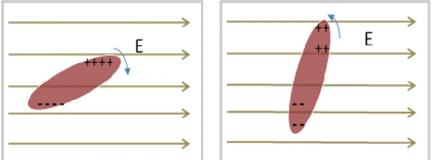
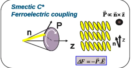
There is another type of smectic C phase which is known as Smectic C* or chiral smectics. The C2 point group symmetry of this mesophase is compatible with the existence of a
spontaneous polarization Ps perpendicular to the tilt plan. In case of chiral smectic phase
as shown in Figure 1- 7, the orientation of the director has a helical distribution with respect to Z-axis. The pitch is defined as the distance when the similar molecular orientation is retraced. This tilt angle induces a spontaneous polarisation perpendicular to the plan defined by the director and the normal to the layers. The SmC* is locally a ferroelectric mesophase. Azimuthal angle can be defined using the projection of the molecule in X-Y plane.
Chapter 1: Introduction to Liquid Crystals
6
FIGURE 1-7:SMECTIC C* AND TILT ANGLE OF THE SMECTIC LIQUID CRYSTALS
Application of electric field changes the direction of the director as shown in Figure 1- 8. The SmC* helix can be unwound by confining the liquid crystal in cell with small thickness, typically few micron (Clark-Lagerwall structure) [6]. This structure, known as bookshelf geometry, allows the switching of the director through the ferroelectric coupling torque:Ps.Esin. When the electric field is applied and upon reversing the direction of the field the director orientation reverses. The half of the angle between these two stable states is two times the tilt angle.
FIGURE 1-8: THE SWITCHING OF THE MOLECULES
The smectic layers in confined geometry have a chevron structure. This structure results from the layer shrinkage observed in SmC due to the tilt of the director. With a strong surface anchoring a uniform layers displacement along the z direction is impossible. The only way is a tilt of the smectic layer in chevron-like structure. Two orientations of the chevron tilt are possible those who induce defects lines between domains with opposite chevrons [7] [8]
Chapter 1: Introduction to Liquid Crystals
7
FIGURE 1-9:COMPRESSION OF LAYERS IN A SURFACE STABILISED CELL
FIGURE 1-10:EFFECTIVE TILT ANGLE IN A SSFLC CELL
Above figure represents Ф as the effective tilt angle surface stabilised ferroelectric liquid crystal cell. This tilt angle appears because compression of the smectic layers in cell geometry.
Chapter 1: Introduction to Liquid Crystals
8
FIGURE 1-11:LIGHTENING AND HAIR PIN DEFECTS 10X OBJECTIVE WITH FELIX015/100(CLARIANT)
The above photos were taken in the laboratory. In above figures one can see how the zigzag defects in smectic liquid crystal look like. The formation of C1 or C2 defect depends upon the surface treatment given to the surfaces and also the pretilt angle of the liquid crystal [7].
1.2 Optical Anisotropy
Another important intrinsic property of liquid crystal is optical anisotropy. These materials have two different refractive indices no and ne; no is the ordinary refractive index
i.e. the electric field vibrates perpendicular optical axis (director) while ne is the
extra-ordinary refractive index where the electric field vibrates parallel to optical axis [9]. The difference between these two indices of refraction is called as birefringence. Birefringence in liquid crystals is temperature (and wavelength) dependent: Increasing temperature causes a reduction of the birefringence until the liquid crystal passes liquid crystal-isotropic transition.
The birefringence property is intensively used to transform light polarisation: A polarised light wave when it enters the liquid crystals it splits into ordinary and extra-ordinary waves and they emerge from the material with a phase shift. The output polarisation is different from the input polarisation. Modifying the birefringence properties can be done by applying electric field on the material. This polarisation transformation combined with an output polariser allows light amplitude modulation. The optical phase retardation in the liquid crystal with thickness d, and birefringence ∆n is given by,
Chapter 1: Introduction to Liquid Crystals
9
Where, λ0 is the wavelength of light in vacuum. Since birefringence is temperature and
wavelength dependent the optical retardation also depends upon these two parameters.
1.3 Dielectric Anisotropy
Dielectric properties of the liquid crystals are related to the response of the liquid crystal molecules upon application of electric field. We have seen that the nematic and smectic have orientational order; hence these liquid crystals possess uniaxial symmetry. SmC has a symmetry which allows biaxial properties, but generally this mesophase is approximated to uniaxial material.
In a dielectric material an electric field E induces electric polarisation P and is given as,
(1-3) is the electric susceptibility tensor.
The electric displacement is given by,
(1- 4) Where, E is the electric field, ε0 permittivity of free space, P is polarisation and is the
dielectric tensor since we are dealing with anisotropic media. The dielectric tensor is given as,
(1- 5) for uniaxial (nematic and smectic A) and biaxial (Smectic C) are given as,
(1- 6)
Where, and are perpendicular and parallel components of dielectric constants, εi is the
components of dielectric constants associated with all three axes.
The difference between these two dielectric constants is known as dielectric anisotropy and can be given as,
(1- 7) The dielectric anisotropy can be either positive or negative.
Uniaxial liquid crystal
Biaxial liquid crystal
Chapter 1: Introduction to Liquid Crystals
10
1.4 Liquid Crystal Switching
In this section we will detail the behaviour of liquid crystal director with different structures with respect to applied electric field.
1.4.1 Dielectric Coupling
When electric field is applied on the liquid crystal molecule with positive anisotropy (∆ε>0) it tends to align itself along the direction or parallel to the electric field. While in case of liquid crystal molecule with negative dielectric anisotropy (∆ε<0) it tends to align itself perpendicular to the direction of the electric field. The index of refraction is larger along the long axis of the molecules. The optical and dielectric anisotropies of liquid crystals enable the index of refraction to be controlled electrically, which is the underlying basis for many liquid crystal display applications.
Figure 1- 12: RESPONSE TO ELECTRIC FIELD BY POSITIVE AND NEGATIVE ANISOTROPIC LIQUID CRYSTAL
1.4.2 Nematic and Cholesteric switching
The dielectric torque govern the reorientation mechanism of both nematic and cholesteric liquid crystal. The dielectric torque is balanced by the elastic energy torque within the liquid crystal and a progressive reorientation is observed increasing the electric field magnitude.
The refractive index of the liquid crystal starts to decrease with the electric field is applied to their molecules i.e. the birefringence value starts to reduce with application of electric field.
Chapter 1: Introduction to Liquid Crystals
11
Figure 1- 13: REORIENTATION OF NEMATIC LIQUID CRYSTAL WITH ELECTRIC FIELD (FREDERICSZ TRANSITION) There is critical field before which the director is not sensitive, but this critical electric field value is crossed the director continue to orient themselves with respect to electric field. In a planar aligned nematic cell the molecules in bulk start to orient to homeotropic direction until the field is reached where the entire cell is homeotropically aligned. Homeotropic state if seen under the cross polarisers appears dark and hence the cell is switching from ON state to OFF state [10]. The critical electric field value is given by,
(1- 8) Where, K1 is the splay elastic constant, d is thickness of the liquid crystal and ∆ε is the
dielectric anisotropy.
Response times for Nematic liquid crystal can be given as
(1- 9)
(1- 10) Where, d is the thickness of the liquid crystal, is the dielectric anisotropy, k11 is the
elastic constant associated with the splay, is the viscosity of the liquid crystal and V is
the applied voltage.
Without applied electric field the structure is planar twisted. The electric field break the helix structure into scattering multi domains texture. Finally increasing the electric field magnitude a homeotropic nematic liquid crystal is obtained.
Chapter 1: Introduction to Liquid Crystals
12
FIGURE 1-14: REORIENTATION OF CHOLESTERIC LIQUID CRYSTAL WITH ELECTRIC FIELD: PLANAR TWISTED (WO ELECTRIC FIELD) TO FINGERPRINT STRUCTURE (W ELECTRIC FIELD) AND HOMEOTROPIC TEXTURE (W HIGH
MAGNITUDE ELECTRIC FIELD)
1.4.3 Ferroelectric coupling
In case of smectic the switching of molecules is slightly different than nematics as these molecules switch between two stable states.
FIGURE 1-15:SWITCHING IN SURFACE STABILISED (BOOKSHELF GEOMETRY)FERROELECTRIC LIQUID CRYSTALS Taking the balance equation between ferroelectric torques and viscous torque, we obtain the response times for FLC, given by following equation.
(1- 11) Where,
τ = the response time (s), = Smectic rotational viscosity (mPa.s), Ps = Spontaneous Polarisation (C.m-2, E = Applied electric field (V.m-1).
Chapter 1: Introduction to Liquid Crystals
13
1.5 Liquid crystal composite material: Polymer Stabilised
Liquid Crystals and Polymer Dispersed Liquid Crystal
The role of polymer stabilisation is double: modify the electro-optic response of liquid crystal and increase the mechanical resilience of the material. For example using a nematic liquid crystal stabilised with a polymer network formed with mesogenic pre-polymer increase the relaxation speed. In the case of ferroelectric liquid crystal stabilisation induces monostable behaviour. These structures are obtained by mixing liquid crystal material with photo-curable mesogenic pre-polymer. The UV radiation induces a polymerisation and a phase separation and finally formation of a continuous liquid crystal structure stabilised by a polymer network [11] [12] [13]. There are several other composite liquid crystal structures. For example using a mixture of non-mesogenic pre-polymer and liquid crystal, polymer dispersed liquid crystals (PDLC) is obtained. These structures are sponge-like with liquid crystal droplets dispersion. Due to the isotropic property of the mixture, the liquid crystal is randomly oriented. These materials have light scattering modulation effect or pure phase shift modulation according the size of liquid crystal droplets that depends on both polymer concentration and kinetic of the polymerisation.
1.6 Potential Technologies of Liquid Crystals
The dielectric nature, the ability of the molecules to orient in any direction, selective reflection, response to electric and magnetic fields, optically anisotropic nature, large birefringence compared to any other crystal, ability to alter the birefringence with respect to applied electric and also with respect to temperature makes liquid crystals an attractive material in wide spectrum of applications. One of the biggest applications in the world is the fabrication of displays based on liquid crystals [14]. Market share of liquid crystals in the display industry has already overtaken the traditional cathode ray tube based displays and soon the latter will become redundant in display industry. As mentioned earlier change in the birefringence with respect to electric field and magnetic field has attracted lot of attention from the world of optical communications. Different types of liquid crystal present with different characteristics and by exploiting these characteristics one can think many applications. In case of chiral nematics or cholesterics, they reflect light depending upon the pitch which allows us many applications like tunable mirrors, colour sensors; also this pitch is temperature dependent this allows us to fabricate thermometers. Smectic liquid crystals are known for their ability switch fast and one can imagine several applications where one requires high speed switching (few tens of microseconds). Apart from these applications other applications like tunable filters, optical imaging, tunable lasers based on birefringence modulation of liquid crystals, failure analysis in
Chapter 1: Introduction to Liquid Crystals
14
semiconductor industry, waveguides based on liquid crystals etc are few of the promising and upcoming frontiers of liquid crystal research [15-17].
Chapter 2: Textures
and Alignment
Techniques of Liquid
Crystal
Chapter 2: Different Techniques of Liquid Crystal Alignment
17
2.1 Introduction to Alignment of Liquid Crystals
One of the most critical aspects of the liquid crystal study is the orientation of these liquid crystalline molecules in a desired direction. Therefore, the study of alignment technologies is by far the most important and subtle feature of the liquid crystal research. The aim of this chapter is to analyse different alignment methods and also to study in particular the photo-alignment in detail. However, before discussing about the photo-photo-alignment technique for aligning liquid crystals, it would be necessary to assess the need of alignment for liquid crystals.
Liquid crystals have not only become the backbone of the display applications but also they are capable of expanding their horizons to a wide spectrum of applications like telecommunications, diffractive optics, holograms, geometrical optics, etc [18] [19] [20]. The orientation of liquid crystal molecules in a desired direction is a prerequisite for many liquid crystal related applications. The groundwork for these numerous applications is an alignment layer deposited on a substrate, which induces an interaction between the substrate and the liquid crystal molecules eventually deciding the orientation of these molecules. This alignment layer is normally a polymer film deposited on a substrate using spin coating or some other means as dip-coating, spraying etc. It usually anchors these liquid crystal molecules either parallel (planar) or perpendicular (homeotropic) to the substrate. A specific treatment is then operated to induce the anisotropy (rubbing, anisotropic polymerization etc.). When the liquid crystal molecules come in contact with the anisotropic surface, the excess free energy of the molecules near the interface will be directionally dependent; the anisotropic part of this free surface energy induces an anchoring that tends to align the molecules in the same direction [21]. The parameters governing the anchoring energy are generally surface topology, the intermolecular forces like Van der Waal, polar and steric between the liquid-crystal-substrate interface [22]. Another important characteristic of the alignment layer is a generation of slight angle to the molecules of a liquid crystal near to the surface known as the pretilt angle. This means that the alignment layer not only exerts alignment in the azimuthal plane but also in the perpendicular direction. The energy supplied to the polymer chains near to the surface of the alignment layer is responsible for deciding the pretilt angle. It is possible to generate pretilts ranging from 0⁰ to 90⁰ making the alignment planar to homeotropic respectively.
Chapter 2: Different Techniques of Liquid Crystal Alignment
18
2.1.1 Alignment by rubbing
The most widely used alignment technique is alignment by rubbing, which dates back to almost hundred years ago [23]. The mere idea and the execution of this technique make it such a remarkable alignment technique that till date it is still used in practice. By simply buffing the polymer film deposited on the substrate using a velvet cloth gives rise to alignment of liquid crystal molecules in the direction of buffing. Although the technique is so simple to align liquid crystal molecules, the parameters governing the orientation of the liquid crystal director are not yet lucid enough. There are mainly two explanations with two governing mechanisms. D.W. Berreman in his famous paper suggests that the rubbing of the polymer surface creates microscopic grooves on the polymer surface along the rubbing direction causing the molecules of liquid crystal aligning themselves along these periodic surface topologies [24]. In the molecular model of alignment first suggested by Castellano [25] and then by Geary et al [26], where they suggest that the rubbing causes a partial melting of few molecular layers of polymer films near the surface because of heat created due to friction and hence the alignment is solely due to the orientation of polymeric chains near the surface of alignment layer parallel to the applied shear field. This gives rise to the local anisotropy of the polymer film and liquid crystal molecules orient themselves accordingly. There are studies where they experimentally prove that the molecular model for alignment is responsible for the alignment [27]. There are studies from different groups suggesting that both these mechanisms play a pivotal part in the orientation of director of liquid crystals [28] [29] [30]. Irrespective of which governing mechanism, the alignment will originate from breaking of the symmetry at the surface of the polymer either macroscopically in case of Berreman model or microscopically in case of molecular model [31]. Like the parameters governing the rubbing mechanism, another important aspect about alignment by rubbing is generation of pretilt angles ranging from 0⁰ to 90⁰, is also ill understood [32]. Several groups have tried to elucidate the mechanism for generation of pretilt angle, which causes by interaction of polymers with liquid crystal [33], [34], [35]. Authors from [36] reported that the pretilt angle of the liquid crystal molecules on rubbed polymer film was determined by several factors associated with anchoring energy, mainly van der Waals forces, steric effect and electronic interaction.
Chapter 2: Different Techniques of Liquid Crystal Alignment
19
FIGURE 2-1:BERREMAN MODEL OF ALIGNMENT BY RUBBING
FIGURE 2-2:MOLECULAR MODEL OF ALIGNMENT USING RUBBING
So far in this section we have been studying about the alignment by rubbing, now we will focus our attention on the execution of this technique for different liquid crystals. In liquid crystal studies, authors usually talk about the “cell”, which comprises of two glass plates separated by few microns using glass rod spacers with a liquid crystal sandwiched between the glass substrates. Studies relating to these cells are normally orientation of liquid crystal inside them and the electro-optical response of the same. The former is the alignment technique and the latter we try to exploit for different applications. When nematic and cholesteric liquid crystals are filled at temperatures above isotropic temperature using a capillary effect in such a cell, which has been fabricated by using two rubbed polyimide substrates; then the molecules of these liquid crystals align themselves in the direction of rubbing. The only matter of detail while fabrication of the cell is that the direction of rubbing for each substrate should be in opposite direction as that of the other i.e. the cell is
Chapter 2: Different Techniques of Liquid Crystal Alignment
20
fabricated in anti parallel fashion in order to have parallel alignment. Alignment of smectics on the other hand presents with some alignment difficulties and the molecular alignment for smectic liquid crystals and also novel method involved in the same has been addressed in coming sections. First, we will focus on the problems involved in alignment of smectic liquid crystals.
2.1.2 Other alignment techniques
Over the last few decades there are several alignment techniques have been extensively developed. This section will briefly address the mode of operation for these techniques. All techniques for the alignment result into an anisotropy of the alignment layer either physically and/or chemically. Here we will be mentioning few of the most relevant techniques. Apart from the techniques mentioned below there are various other techniques used for liquid crystal alignment; [12] takes brief overview of the existing technologies, their characteristics, the quality of alignment and their industrial feasibility.
2.1.2.1. Alignment by oblique evaporation of SiOx films
Liquid crystal alignment on the substrates can be controlled by the vacuum deposition of Silicon oxide films. The direction of the alignment is decided by the incident angle of the deposition [12]. Topology of the surface formed by the oblique evaporation is normally grooved like [37]. The magnitude of the anisotropy depends upon the angle of incidence between the surface of the substrate and the direction of evaporation, which shows that the direction of the liquid crystal director is a function of the same angle. From liquid crystal display the point of view the deposition of insulators like silicon oxides induces uniform alignment over patterned electrodes; they provide strong and stable alignment. Also, these inorganic films can sustain the temperatures up to 500⁰C [38]. Generation of pre-tilt angle starting from 0⁰ to 85⁰ can be precisely controlled using this technique. However, the cost of vacuum deposition technology and also because of lack of in plane uniformity of this technique makes industrial feasibility of it poor [32].
2.1.2.2. Micro-patterned polymers
This particular alignment method is made by photolithographically patterning the microgrooves on the polymer surface [32]. This mechanical process furnishes periodic topologies to the polymer surfaces giving rise to the physical anisotropy in the direction of the microgrooves. The principle of this alignment method follows closely the principle of Berreman’s model for alignment by rubbing [24] of having periodic structures on the substrate. The periodic pattern is made by the master mould and it is further transferred
Chapter 2: Different Techniques of Liquid Crystal Alignment
21
on the surface by stamping method. It is obvious that no re-orientation of polymer chains occurs and the alignment is solely due to grooved structure [39]. The liquid crystal molecules show fair long range order when confined to these microgrooves. Increase in the anchoring is observed with increase in the groove depth; however, it decreases with increasing the spatial period and the groove width [39].
2.1.2.3. Ion beam etching surfaces
There are two different approaches for achieving topological anisotropy using this technique; the first one being the bombardment of ion beam on to the substrate to form a film that can be used as an alignment layer and in the second method, bombardment of ion beam on to the already deposited film in order to achieve the alignment. Ion energy, the dose of ion bombardment and the angle of incidence are various parameters who govern the anchoring strength of the alignment layer. Pretilt angle is found to be function of ion beam incidence angle and the dose of the ion beam [40].
2.2 Introduction to Photo-alignment of Liquid Crystals
Anisotropic distribution of the alignment layer molecules by using the directional dependence of the polarisation of the incident light absorbed by these molecules is commonly known as photo-alignment. When an electric vector of the incident light wave is in concurrence with the transition moment of the molecule, the molecule strongly absorbs the light causing a photochemical reaction [12]. This particular process of aligning liquid crystal molecules is widely reckoned as a potential substitute to conventional alignment by rubbing as it possesses some obvious advantages as compared to its traditional counterpart. From the point of view of liquid crystal displays and also for other liquid crystal based devices, alignment due to traditional rubbing technique causes several problems; the quality of rubbing cloth degrades over the period of time due to repeated use causing the degradation in quality in alignment and also requires precise adjustment of the rubbing apparatus, rubbing traces reduce the contrast ratio, electro-static charges created due to friction damage the TFT based LCDs, alignment patterning within the individual pixel is not possible, since the pressure while rubbing varies on the elevated LCD substrate causing non uniform alignment and tilt angle discrepancies resulting in degradation of the grey scale; rubbing leaves debris on the substrate while the photo-alignment technique clean and dust free [32]. Moreover, rubbing technique is well suited to large substrate sizes and it is not at all suited
for small components. To circumvent these problems photo-alignment has attracted strong
interest because it is a contact free method, allows multi patterning with possible use of photo-masks, fine control over the pretilt and precise optical liquid crystal alignment. In 1988 Ichimura et al had reported for the first time isomerisation of azobenzene which
Chapter 2: Different Techniques of Liquid Crystal Alignment
22
showed reversible photo-alignment [41]. In early 1990s two independent methods for photo-alignment were invented; first in 1991 Gibbons et al used azobenzene doped polyimide when exposed to linear polarised light aligns the liquid crystal molecules [42] and second in 1992 Schadt et al reported the photo-alignment using dimerisation of poly (vinyl cinnamate) exposed to linearly polarised UV light [22]. Photochemical reaction occurring during photo-alignment can be roughly categorised in two reactions viz. photoisomerisation and photodimerisation Gibbons et al used the former method whilst Schadt et al used the latter.
2.2.1 Photo-alignment using photoisomerisation
Photoisomerisation brings about a phase transition enabling the switching between two states with different molecular orientations. When a polarised ultraviolet light of appropriate wavelength is incident on the azobenzene dissolved in liquid crystal medium, azobenzene molecules experience trans-cis isomerisation, the dipole of the double bond aligns perpendicular to incident polarisation resulting in uniform alignment [43]. However, if the irradiation is continued the concentration of cis form will increase with time. The shape of trans form converts rapidly into the cis form and latter possessing more surface affinity rests near the cell walls. The combination of these two effects was used by Gibbons et al to demonstrate the first photo-alignment based LCD. Control over the pretilt angle can be achieved by making the exposure in two stages; first exposure aligns the liquid crystal molecule and in the second exposure by rotating the axis polarisation of polarised UV liquid crystal molecules will re-orient equal to the angle of rotation. Ichimura et al showed that the reversible change in the alignment i.e. the switching between homeotropic and homogeneous alignment can be achieved by perpendicularly aligning the azobenzene molecules in liquid crystal medium [41]. Successively, these molecules can be switched between different alignment states by using appropriate UV wavelengths. These azobenzene materials have the ability to switch the orientation of liquid crystal within the plane and therefore, they were called as the “command surfaces”. However, all the azobenzene based photo-alignment systems have one major shortcoming and that of the stability. Due to random cis-trans isomerisation and in-plane thermal motions lead to stability lasting from seconds to months [43] restraining the use of photo-alignment systems in liquid crystal applications.
Chapter 2: Different Techniques of Liquid Crystal Alignment
23
FIGURE 2-3:PHOTOALIGNMENT OF LIQUID CRYSTAL USING GIBBONS METHOD
2.2.2 Photo-alignment using Photochemical Process
Since the process of aligning molecules using the azobenzene was not stable enough, one of the first substitutes for this method was use of molecules based on cinnamic acid. As these molecules are capable of not only undergoing the cis-trans and trans-cis isomerisation but also capable of undergoing (2+2) photocycloaddition reactions upon irradiation of UV light. Schadt et al proposed for the first time photo-alignment using poly (vinyl-p-methoxy-cinnamate) (PVCi); irradiation of polarised UV on spin coated PVCi provided the anchoring for liquid crystal molecules [22]. This paper turned out to be one of the milestones of the liquid crystal alignment research triggering the massive interest in the process and also in industrialisation of the same. Prior to the UV exposure PVCi molecules are isotropically distributed. When PVCi films are illuminated by linearly polarised UV light, different cross linking rates occur between the cinnamoyl side chains parallel to direction of polarisation and cinnamoyl side chains perpendicular to polarisation direction causing local anisotropy, which results in a linear dichroism and birefringence [44]. The choice of the UV wavelength is made on the basis of the absorption spectra of the PVCi; if the used wavelength lies in the absorption spectra then linear photopolymerisation of this wavelength will lead to optical anisotropies and homogeneous alignment. Unlike the photo-alignment using the azobenzene here the (2+2) cycloaddition method is more dominant than the cis-trans transitions [22], although the latter do take place during the
Chapter 2: Different Techniques of Liquid Crystal Alignment
24
photochemical process. During the photopolymerisation double bonds parallel to the polarisation direction are broken, eventually getting reconnected and dimerised. There is no optical anisotropy before the UV irradiation; however, immediately after the polarised UV light is incident on PVCi, a weak anisotropy is observed, it increases rapidly with time saturating after certain UV dosage. Non dimerised side chains of PVCi have anisotropic shape giving rise to large refractive index along these chains (slow axis); thus, the slow axis of the photo exposed film lies perpendicular to polarisation indicating large population of these side chains. From the point of view of chemical structure of the PVCi there are three molecular entities, which play the important role in LC alignment. Cinnamoyl side chains, the cyclobutane photoderivatives and the hydrocarbon main chains [22]. The anisotropic interaction forces of these molecular entities lie in the same direction and hence it is considered to be responsible for the planar alignment of LC molecules [22]. This LPP alignment has advantage over the alignment using cis-trans isomerisation of being able to generate the linear alignment and also the pretilt in one exposure or simultaneously. Following figure shows the (2+2) cycloaddition reaction and also the direction of the molecular alignment. This process was later on industrialised by an enterprise called ROLIC, which produced photo-alignment materials for different optical devices. Two different products for aligning the liquid crystals were proposed. The first product was
Linearly Photo-polymerisable Polymer (LPP), which is an alignment layer which undergoes
the exposure to linearly polarised light in order to boast optical anisotropy on the substrate. The second photo-alignment product was Liquid Crystal Pre-polymer (LCP), is a liquid crystal-polymer solution used in combination with LPP to fabricate compensation films for various liquid crystal based applications. LCP is normally deposited on already photo-aligned LPP so that the molecules of liquid crystal align themselves with respect to anisotropy of the LPP layer. LPP layer possesses some useful properties from the point of view of liquid crystal applications; it has high photosensitivity, can generate high contrast ratio due to excellent orientation quality, high thermal and humidity stability, high pre-tilt angles in combination with LCP and can be patterned with high resolution (LPP datasheet from ROLIC). LCP also possesses properties like high thermal and humidity stability; it can withstand intense light intensities (LCP datasheet from ROLIC). The experiments mentioned in this chapter are performed using the combination LPP and LCP for few liquid crystal based applications.
Chapter 2: Different Techniques of Liquid Crystal Alignment
25
FIGURE 2-4:(2+2)CYCLOADDITION OF AZOBENZENE MOLECULES
2.3 Photo-alignment of different liquid crystals
So far in this chapter we have been studying about the different alignment methods, now we will focus our attention on the execution of these techniques for different liquid crystals. As mentioned before in order to align the liquid crystals in desired direction we make use of the liquid crystal cells. In this section, first we will see alignment of nematic and cholesteric liquid crystal in such a cell. Applications based on photo-alignment are discussed in a separate chapter. Photo-alignment of smectic liquid crystal is also discussed in following sections.
2.3.1 Photo-alignment of Nematic Liquid Crystals
As mentioned above for the experiments involved in this section we have used the commercially available products LPP (ROP 103 – commercial name) and LCP (ROF -5102) from ROLIC for photo-alignment purposes. In order to prepare a well aligned nematic cell, we took two clean glass substrates. These two glass substrates were first coated by LPP at 3000 RPM for 60 seconds. The thickness of the LPP substrates was approximately 50 nm. They were later dried at 180⁰ C for 5 minutes. Then they were separately exposed to linearly polarised light at energy of 1 J/cm2 with a source of wavelength 300nm, the
direction of electric polarisation was kept parallel to one of the sides of the substrate. LCP is manufactured for compensator films; hence at higher spin speeds also the thickness of
Chapter 2: Different Techniques of Liquid Crystal Alignment
26
LCP film is few hundreds of nanometres. In order to provide sufficient anchoring energy to nematic liquid crystal molecules; LCP was diluted using the solvent cyclopentanon (same used by manufacturer for LCP) to as much as 3% of solid content (original solution is 25% of solid content). Technique of aligning the liquid crystals by fine liquid crystal film is similar to the technique proposed by Yaroshchuk et al, as it improves stability of the liquid crystal alignment [45]. This diluted solution was coated on the photo-aligned LPP substrates at 3000 RPM for 60 seconds. The newly coated substrates then underwent heat treatment strictly between 50-52 ⁰C for 3 minutes to align the liquid crystal molecules in the direction of exposure. Then, they were polymerised using unpolarised UV light under
nitrogen atmosphere with energy of 500mJ/cm2. The thickness of LCP was approximately
100nms. Mixture of glue with glass rod spacers with appropriate thickness was prepared; the prepared substrates were glued using this mixture in anti parallel manner i.e. the polarisation directions in substrate one and substrate two were kept in opposite direction. Any commercially available nematic liquid crystal can be filled in this cell above isotropic temperature of the nematic liquid crystal. When cooled down planar alignment of nematic liquid crystal is obtained. It was observed if only LPP was used without further deposition of LCP, the alignment was homeotropic. It is worth noting that the norms for heat treatment for LCP must be followed in order to achieve perfect alignment. Pre-tilt angle adjustments can be done by exposing the LPP substrates in a slanting position rather than in horizontal. Please note that the pretilt angle is independent of slanting angle and it is only decided by adjusting the exposure energy (further details about pretilt angle generation can be found in LPP datasheet). Fabrication of twisted cells is possible by changing the angle of polarisation by appropriate value. Following diagram represents schematically the protocol for photo-alignment. UV filter is used during the first exposure in order to remove unwanted UV wavelengths. The anchoring energy to nematic liquid crystal molecules is provided by the LCP molecules as they themselves have undergone a planar alignment. The twisted nematic cells can be obtained by rotating the substrates only by 90⁰ than by 180⁰. High contrast ratio can be observed as the extinction of light in OFF state is very good.