Portable Tool for Finalizing Freehand Drawings:
Activity Analysis and Design Requirements
Christelle Boulanger
Françoise Decortis
IKU
University of Liège-SPTE
Blvd. du Rectorat, 5
B4000 Liège - Belgique
[surname.name]@ulg.ac.be
Stéphane Safin
ABSTRACTWithin a multidisciplinary team of designers, architects and mechanical engineers, and ergonomists, we participate in a research project (ICC) in design and creative interface. This paper describes a participative and iterative approach and reviews the results of field studies involved in the design of a portable tool for finalizing freehand drawings. The results are discussed in terms of Activity Theory and its contribution to this field.
Keywords
Activity Theory, human engineering, ergonomics recommendations, concept development, instrumental approach
INTRODUCTION
Within a multidisciplinary team of designers, architects and mechanical engineers, and ergonomists, we participate in a research project (ICC) in design and creative interface. The goal of this project is to design and develop a portable tool for architects and engineers that enables them to finalize freehand drawings.
To realise the drawing of a house or a field, to modify a plan or to update it are inherent tasks to the activity of the architect, the geometer and the engineer. But if those tasks are important and considered as a necessary step to the problem's understanding by professionals, the finalizing of those planes is more negatively perceived. Indeed, the current programs need a very long and fastidious encoding. Those softwares all belong to the WIMP generation (window icon mouse & pointing) of which the analysis of the inducted operating modes shows that they do not fit to the designer's natural expressive modes. They even deform the cognitive model that the designer has about his task. That is why in the hands of engineer, architect, designer, geometer or field technician, paper and pen still remain as the best supports in their daily tasks. Moreover, during the finalizing of hand drawings realised on site, the architect may run up against incoherencies and be
constrained to go back on the field to find out the mistake. From those round trips result a lack of time, which could be avoided if the drawing activities on site and their digital conversion could be realised in one time. This is the aim of the development of the IC&C tool.
Various technologies are combined to develop this tool. They included pen-pad computer technology and voice recognition. The object is to find a means of understanding and interpreting spontaneous expression by architects and engineers while they work.
This research uses recent technology to interact with the system, i.e. the combination of a portable computer with digital pad and electronic pen, wireless earplugs/microphone and a radio communications system (WI-FI) providing Internet access. User creates drawings. A multi-agents system interprets lines, drawings and speech data, and sends it to a graphical file server. The server sends the finalized plan to the user in real time.
Our goal is to implement a user-centered approach for developing the tool. Based in Activity Theory, our approach consists of two main principles. The first involves orienting development questions on the basis of analyses of actual professional activity during scale drawings and correction of drawings. The second is to validate the development of functions and interface with the professionals who are the intended users. The user-development loop that is formed provides for continuing iteration and better anchoring of the tool in real activity. Activity is analyzed on the basis of the theoretical frameworks of Activity Theory and Instrumental Approach (Rabardel, 1995), which examine activity through various relationships between the subject, object of the activity and the instrument used.
The richness of the approach used for the development of the tool is based on continuous consultation between the various project partners and combining data generated by users, designers, developers, and
ergonomists at each stage of the development
.
This paper presents the initial results of the activity analyses that either guided the development of the tool or led to new research questions. We discuss these results within the framework of Activity Theory and its contribution to the development of this sort of tool.
CONCEPTUAL FRAMEWORK
Activity Theory (AT) responds to the needs of research involving new technology. It enables us to understand and describe the context, the situation and the practical applications into which these technologies will be integrated. This theory is based on the assumption that the technology used is not limited to a simple mechanical input-output relationship between man and machine, but rather requires a much richer description of the user situation in order to design and evaluate new tools. According to this theory, information processing cannot be modeled in the same way for both man and machine. Artifacts that serve as the mediators of human thought and behavior do not occupy the same ontological space as the persons involved (Nardi, 1996). That means that systems must not only be usable, but also be useful. In this case it is imperative to understand what is useful to a person in that person’s work, but also to understand how a technology can be integrated into the current social and material environment of the user. In answering these questions, the AT analysis unit is not limited to human actions, because these actions are situated in a context, and it is impossible to understand them outside of this context (Kuutti, 1996). This means that the combination of actions and the context in which these actions take place constitute the activity; this activity is the special unit of analysis of AT. The activity cannot be grasped without concomitantly understanding the role of the artifacts used in the daily environment and the manner in which they are integrated into social practices (Nardi, 1996).
From this point of view, the activity consists of transforming an object (perhaps tangible or more abstract, like an idea) through the intermediary of an artifact.
Within the framework of designing a new tool, it is important to understand and to explain the work situations that currently exist in order to formulate hypotheses that help to guide the conceptualization of the tool. This has to be done in such a way that it is adequately integrated into the activity and properly fulfills the criteria of utility and usability, while increasing the prospects of the activity without modifying it.
The analysis of the relationship between the subject and the object of its activity, including the artifact, make up a rich source of information essential for understanding the activity before a new tool is introduced, taking into account both the real need for this tool and what it is supposed to accomplish.
Observation of the relationships that more specifically relate to the artifact lead to a more restricted but also more precise field of investigation than AT. This is the
domain of the Instrumental Approach (Rabardel, 1995). In this approach, the term artifact is redefined to include the concept of the instrument. This means that the artifact, which has no special relationship to an object, becomes an instrument when it is involved in a use “as a means that [the subject] associates with his action” (Rabardel, 1995). In this approach, people modify artifacts and adjust them on the basis of their specific conditions and needs, becoming competent in the use of these artifacts (logic of operating), with an understanding of the tasks that can be performed with these artifacts (logic of transforming things), and the methods that can be used for effectively carrying out tasks (logic of activity and use). The artifact becomes an instrument because it is part of an instrument-action relationship.
This movement of the artifact towards becoming an instrument implies orienting the design in a manner so that artifacts can be effectively transformed into instruments in the user’s practical application. These new tools should be flexible and open-ended, so that they can be modified by the user and adjusted on the basis of the tasks to be performed, even if these tasks have not been anticipated. In order to design such tools, it is important to take into account current practices and the real needs of users. Béguin (2003) describes this as a mutual learning experience between designer and user, each of whom has a different experience with the tool. We use Activity Theory and the Instrumental Approach to answer pertinent questions in the analysis of design activities, and in that respect we consider the various relationships between the subject, object of its activity and the instrument that is used. In these activities, the subject corresponds to the architect or engineer, and the object of the work is the production of a drawing or plan. Conventionally, the instruments used may be a notebook and pencil, a ruler, a laser and a computer. Pertinent questions on the relationship of the subject to object can then be: what are the phases that structure the activity? Which of the subject’s actions are implemented, and more precisely, what operations are carried out through what means? Questions bearing on the relationship of the subject to its instrument refer to the manner in which current tools are used. Here, the analysis is based on characteristics of activity contexts and will guide us through the HCI features of the future tool. The relationship between the instrument and the object is based on the possibilities of the systems used. Analysis of this relationship enables us to develop the system’s functions and to attempt to provide “added value” to the activity. The analysis aims to answer the following questions. How does the instrument support each phase of the activity? How can it enrich these phases? In the relationship of subject-instrument-object, the idea is to understand the activity in relation to the new instrument in order both to predict transformations of that activity and to derive specific response to questions of its usability. The object is to understand how the instrument modifies the activity of the subject, its modes of action, strategies and thought structures.
METHODOLOGICAL FRAMEWORK
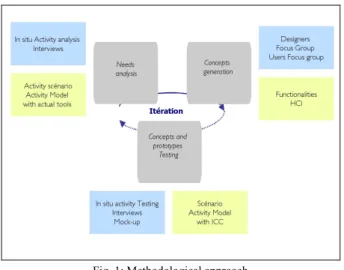
Basing our research on Activity Theory, we are taking a pragmatic standpoint, consisting of field studies that will enable us to understand the current and future activity of professionals in these fields. Our approach is solidly anchored in user activities from the very first phases of designing the tool. It is continually enriched by using an iterative process throughout all phases. !The first phase is an analysis of needs. It aims to gather information on general aspects of the work performed by architects and engineers, to target pertinent situations for application of the tool and also to analyze pertinent in situ activities of users and their current tools (paper and pencil, conventional CAD software, etc.).
!The second phase consists of generating tool development concepts based on the results of user activity analyses, and this work is substantiated through the focus group consisting of developers and user groups. This phase also serves to develop the tool’s functions and interface characteristics. The idea is to use real contextualized activities that are natural for the user in order to draw lessons for developing the tool.
Fig. 1: Methodological approach
The last phase is the evaluation phase, where the various concepts and prototypes are tested. Since this implies returning to real situations, new needs can be identified and new concepts generated, which in turn will be evaluated. This continually renewed iteration continues until the final evaluation of the tool. Figure 1 outlines the phases of the methodological approach.
Analysis of needs
The first part of the analysis of needs consists of understanding the architectural and industrial design process, so as to identify pertinent situations where freehand drawing is performed and finalized. This aspect was examined in a preliminary study where we interviewed six architects and six engineers, three of whom worked in a design office, one was responsible for positioning cranes on worksites for a lifting company, and two worked in the area of mechanical design. At this level, our object for each situation identified consisted of defining the type and context for
using the drawing (Figure 2).
The next part of the analysis of needs examined previously identified situations in which the designer’s spontaneous graphic expression can be usefully finalized. The activity of making scale drawings appeared to be the most pertinent of these situations, both for architects and engineers. This activity became the focal point of our investigation. We accompanied five architects and one engineer when they were doing their scale drawings. In this manner we were able to observe the progress of the scale drawing, and also its finalization. We filmed each of these activities in order to identify the context of making a scale plan. We questioned each person on the objective of the scale drawing, for whom it was destined, and what prior information was available to the person making the drawing. A number of clarifications were requested at various moments during scale drawing and finalization. Some examples of these questions are: “What are you
measuring?” or “When you once again draw this room on the computer, how do you define the angles that are not on your scale drawing?”
Fig. 2: Process of identifying target situations Generating concepts
The analysis of scale drawing and finalizing activity in real situations enabled us to make certain recommendations and to perceive their implications for the design of the tool. These recommendations are organized into categories based on relationships between the elements of the activity, namely on subject-instrument-object. They are: 1) the context of the activity, 2) the actions of the subject on the object, 3) the use of the instrument. On the basis of these recommendations, two types of focus groups were organized
Focus group with designers and developers
Every two months, a focus group is organized with all members of the team, architects, designers and the mechanics, developers, computer specialists and ergonomists. During meetings of this focus group, we presented the team with recommendations based on the activities and illustrated them with examples observed during fieldwork. Each recommendation was discussed with the intention of developing one or more concepts for the future tool.
Focus group with users
Other focus groups were made up of representatives of the users and ergonomists. One of their roles was to develop new concepts and functions that had not been anticipated by the project members. Another rule was to discuss and use structured exercises to test the concepts developed by the project group. Two groups of seven users were formed. Each group met once every two months. The first group consisted of five architects and three engineers; the second of five architects and one engineer. Using this formula to test certain concepts offers the advantage of rapidly providing an idea of the merit of the concept, and it enables the project team to receive alternative concepts from the users.
Evaluation
Some of these concepts were embodied in specifications, so as to be implemented and then tested. Others, that implied more significant programming and development, were first tested using mock-ups or other sorts of simulation, and subsequently implemented or not on the basis of test results. Transforming concepts into a new function or a new possible way of using the future tool is an aspect regularly discussed with the developers.
Follow-up document for recommendations
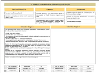
In this manner, each recommendation was individually analyzed and then centralized in a recapitulation document, which was updated after each advance: type of testing and results, implementation or modification. This document can be consulted by each member of the team, and it is presented as support for discussion during focus group meetings with developers. According to Vinck (1999), it is not sufficient to juxtapose points of view from different fields; it is also necessary to establish connections between them and to compare them. In this manner, the quality of exchange depends on the “intermediary objects” that are produced and mobilized in the action. The follow-up document of recommendations is a common object here, containing the points of view of the ergonomists in terms of recommendations, integrating the points of view of the designers in terms of concepts and of developers in terms of the detailed specifications. Figure 3 below shows the example of a page of the follow-up document of recommendations.
Fig. 3: One page of the follow-up document of recommendations The title line at the top of the page indicates the object analyzed in this activity. The next three columns show the recommendations made, the concepts developed by the whole team (designers and ergonomists) and any possible remarks. The first of the next two large boxes contains detailed specifications on how the user should use the tool to carry out the action in question. The second box is used to indicate possible modifications after testing. The boxes at the bottom are checked on the basis of the situation. The box “have a meeting” is checked when the object of the activity to be analyzed needs to be discussed more precisely before further implementation. The box “make a mock-up” is checked when the concept evidently needs prior testing in the form of a simulation. The box “to be implemented” is checked when the technical development is more easily implemented, and modifiable in case testing leads to a negative evaluation of the function. The next three boxes specify the type of testing to be carried out, namely “in situ”, “during focus groups with users” and “in the laboratory in the form of controlled experiments”. These last three boxes indicate the level of progress after testing the object of the activity concerned.
The testing having been carried out at this stage, the specifications can be accepted (“OK”), can be modified or implemented. In the case of modification, a new set of specifications is drawn up and new testing is carried out.
In situ tests lead to other analyses of activities, which may lead to new recommendations. These new recommendations are then subjected to the same process, leading to actual implementation of the concepts involved.
RESULTS
Our preliminary analyses consisted of understanding the context of making and using plans in the professional situations of architects and engineers, as well as identifying what activities occur at what times and in what contexts.
Activity of architectural design
During the design process, the architect uses various drawings:
• The scale drawing is carried out in the initial phases of the design process. Most architects consider it as important, because it is a good means of immerging oneself in the site and, when building transformation is involved, of understanding how the building was constructed.
• The sketches are made on the basis of the scale drawings and information in the program. They usually consist of several lines and annotations intended to organize the architect’s thought. They contain practically no symbols and are only meant to roughly fill in the various spaces. They are intended for the architect’s personal use and are rarely shown to the client. • The project plan is the finalized plan that will
be presented to the client. It consists of a top plan of each level and a cross-section. Some architects add a 3-D view or a perspective drawing. The walls, windows and furnishings are indicated, as well as the dimensions of the rooms, the exterior dimensions of the building, the windows, distances from site boundaries, and building location. The project plan may be modified a number of times on the basis of discussions with the client.
• The building permit includes all technical data. • A proposal plan is completed with all technical
details and specifications that include materials to be used, measurements and amounts necessary.
• The working plans are the plans used on the worksite. These plans may be modified during the construction in order to resolve problems. • The “as built” plans are the final plans at the
end of the building construction.
Activity of industrial design
The field of industrial design varies greatly, with highly specialized sectors ranging from automotive design to strength of materials, and including printed circuits. The drawings for most of the sectors are made directly using CAD software. In fact, there are very few areas in the field of mechanics where two-dimensional drawings are used. Most engineers work directly in 3-D. It seems that mechanical designers tend to replace paper and pencil with functional analyses in text format.
On the basis of these observations and the definition of the tools, the decision was made to focus on two types of activity: the engineering design office and lifting companies. These two sectors have common characteristics, particularly in terms of frequent field trips (for scale drawings or other needs) and their nearly exclusive use of two-dimensional plans.
Engineering design offices may carry out preliminary studies for long projects. This phase consists of
evaluating the means needed to carry out the project. It is based on existing plans.
To the extent possible, design is based on plans. If no plans are available, a succinct scale drawing is used. A solution is proposed on the basis of sketches. The following stage is where the sketches are verified by being drawn to scale in blueprints. The object is then to update plans with new elements. It seems that designing is increasingly done directly on CAD software. The design often involves a number of people, and it appears that computer monitors are not an adequate media for discussion.
The border between “design” and “updating” is not always completely clear: when a new element is designed for a mechanical assembly, all plans of this assembly are automatically updated. This means that during an update some parts of the assembly may be completely omitted from the plans received. Retracing these elements is part of the work of industrial design. Plans may arrive at the design office in various formats: CAD file, bitmap file or on paper. Sometimes there are no plans at the outset. The process consists of using existing assembly plans to verify the dimensions and information necessary for the plans needed, and to control or modify plans so that they correspond to realities in the field.
The work of lifting companies is to place various cranes on the worksite, and to handle and deliver loads to specific places at specific times. The engineer uses worksite plans to decide where the cranes will be placed.
In our initial analysis, the activity of scale drawings and modification and updating of plans appeared to be the most pertinent aspects for developing a tool. The graphic work in both of these activities is carried out freehand, with plans finalized afterwards. Consequently, these are the activities that we analyzed in detail, using analyses of the videos made in the field. At this stage of the study, only the activity of scale drawing and finalization were evaluated.
Activity of scale drawing
The detail drawing can be made in the various contexts depending on the type of architectural or industrial project: detail drawing of a worksite, parcel, building or a part of the building. The dimensions of a site to be drawn may range from 1 meter, in the case of a stairwell, to a number of kilometers for certain industrial sites. In the same respect, the environment may vary from very hot to very cold. The noise level may be relatively high and the area of the scale drawing may be very dusty.
In addition, the scale drawing is usually done with a pencil, ball point pen and a paper tablet, usually in A4 format. This media can be turned in every direction, oriented so that the person doing the drawing can face the section that is being drawn. At any time, this media can be used and placed on support that is stable or not when the professional takes measurements or needs more freedom of movement.
The scale drawings may be made on a number of sheets of white paper or scale paper or on existing plans consisting of a copy of a CAD plan or scanned blueprint.
The contents of the scale drawing also vary on the basis of its objective. The scale drawing for a building renovation may be accurate to a centimeter, whereas scale drawings of a stairway need accuracy in millimeters. The precision of the measurements only needs to be relative for the building renovation, but is critical for a stairway. Scale drawings of a site that is going to be transformed require updated building and site plans and additional plans for placement of machinery and cranes in the case of a hoisting and listing company, which has to place its objects in relation to the particular characteristics indicated in an existing plan. In addition, scale drawings may contain various sorts of annotations (specifying existing materials, explanations of the elements indicated, reference to another drawing or to a photograph, etc.), which are directly or indirectly related to an element of the plan, and which may be written in any direction on the media, up and down the sides, upright or upside down.
The professional can enhance scale drawings by adding specific detailed drawings for specific parts of the general blueprint, or add elevation drawings. Sometimes colors are used, particularly to differentiate plan lines from lines indicating dimensions. The person may overload a single page or decide to continue a single drawing on the next page. And errors may occur during these scale drawings, which means returning to the site to verify some measurements or to complete others, in order to finalize the drawings. Figure 4 illustrates the activity of scale drawing.
Fig. 4: Activity of scale drawing Activity of finalizing
Scale drawings are finalized in a more or less precise manner, depending on the intended use of the plan. This means that the number and types of measurements or the elements necessary may vary, in exactly the same sense as the precision of the measurements. The eventual use also determines the standard chosen for colors that correspond to line thickness.
We observed that the actual activity of finalizing a drawing includes a set of elaborate cognitive processes, and is not limited to simply making a clean copy. This implies that it is difficult for an architect to finalize scale drawings done by another architect, even if both
have the same level of knowledge. It would also seem difficult for an architect to return to his own scale drawings if they were made too long before. Professionals explain these difficulties on the basis of several elements. On one hand, the symbols and abbreviations used by one person are not necessarily the same as those used by another. On the other hand, during their scale drawing an architect stores information “in his head”, information that does not exist or only partially exist in his notes. When the scale drawing is being finalized, this information is necessary to complete the plan and to eliminate uncertainties, incoherencies and imprecision in the measurements. This information is completed by photographs that recall particular aspects of the building or the element that was drawn to scale. Other information is then added. It consists of the architect’s implicit knowledge in the domain of the object that is being drawn to scale. This knowledge will enable the architect to determine the acceptable degree of imprecision, a factor that depends on the context and the nature of the scale drawing. Figure 5 illustrates the activity of finalizing.
Fig. 5: Activity of finalizing
In the next part of this paper, we present the results of our field studies and focus group meetings with users, both in terms of recommendations and implications for tool design. This will be illustrated by several examples of concepts developed during the focus group meetings that included all members of the team, designers, developers and ergonomists.
Implications for design
A number of important elements emerged from this research.
Portability
First, we consider the scale drawing. The analysis of various contexts for carrying out a scale drawing led us to expand the concept of portability. The tool not only has to be portable and relatively light, it also has to be easy-to-use and handle, while robustly resisting shocks and atmospheric conditions, and it must provide proper voice recognition in noisy environments.
One of the first concepts was a PC tablet, which offers the advantage of being portable, and combines the normal features of a digital pad and a computer in a single tool. However, tests carried out with the PC tablet (figure 6) showed it lacked the light weight, easy handling and robustness required. Other solutions are currently being evaluated, in an attempt to find the best response to requirements of this task.
Fig. 6: Activity of scale drawing with the PC tablet
Handling characteristics
Being able to turn a media in any direction is a technological challenge that has to be overcome in providing a tool for these engineers and architects. This ability to turn the media is no small point: it enables the user to face the part of his environment that is being represented. By repositioning the drawing, the person eliminates what would be an additional task, that of reconverting the image in relation to the environment.
Importing the plan
We also studied the possibility of doing the scale drawing on an existing plan, which led us to very different types of base plans, namely active and inactive. Active base plans are vectorized plans imported from another system, and that can be modified on the basis of the user’s needs, providing a finalization that includes the user’s changes. Inactive base plans consist of bitmap images that can be used for reference, by placing them under the scale drawing itself. The function of modifying vectorized plans raises many problems, such as understanding what the modification of an element should contain in relation to other unconnected elements, without complicating the user’s task. This question will require further study.
The variety of content in scale drawings results from the goal of the drawing. This is the reason why we believe it is important to understand the scale drawing in its more global context, to provide properly adapted support for this activity.
Actions on the plan
The types of actions carried out on the plan, just like the representation of a detailed plan or elevation plan, lead us to consider various functions that would enable the user to carry out these actions while maintaining a coherency that could be used by the tool. Some operations, such as zooming in or cutting part of the plan are derived from these recommendations. In the same respect, the tool has to be able to function when errors are made. We also considered the type of feedback and how to inform the user without disturbing this person in the middle of a task.
The activity of finalization raises other important points in the development of the tool.
Finalized plan
In this respect, both the architect and the engineer use different internal and external resources to finalize a scale drawing: notes alone are not sufficient. Each
organizes his thoughts on the basis of a number of representations that each constitutes part of a puzzle. The professional assembles these parts to produce a clear and accurate plan. This means the transition from a scale drawing in the field to a finalized plan implies that both the architect and the engineer take into account field notes on the site or building and other information that is stored “in his head”. Among other things, this mental approach integrates all implicit knowledge of the person in the domain concerned by the scale drawing. These considerations now lead us to resituate the plan finalization within a broader cognitive context and to consider the manner in which the tool could support these tasks, while maintaining a balance between the functions of the professional and operations that can be automated.
DISCUSSION
The activities involved in architectural and industrial design are analyzed from the angle of drawings that organize the activity, and more particularly, on understanding how these drawings are made (freehand then finalized, directly finalized and freehand but not finalized) enable us to target the situation of the scale drawing as being the most pertinent situation in the development of the tool, and this holds true for both architects and engineers.
The two activities that make up the situation of the scale drawing (the scale drawing and its finalization) were subsequently analyzed from the point of view of each of the relationships that make up the context of the activity, with this analysis based on Activity Theory and Instrumental Approach.
The situation of the actual scale drawing, and the combination of the scale drawing and its finalization are distinct activities, carried out one after the other but in different timeframes. The results of this analysis have implications for the development of the tool, and these implications are connected with the actual method that is implemented during a scale drawing or its finalization:
• The study of the context surrounding the activity of the scale drawing enabled us to broaden the concept of portability into a finer grained concept of ease-of-handling and robustness
• The analysis of the relationship between the subject and the actual instrument orients us towards ease-of-handling, where the media can be turned in a manner that is nonrestrictive • the study of the relationship between the
subject and the object of the subject’s activity (the scale drawing and the finalized plan) specifies the context for using this object (import and that export), but also the actions that the subject performs on the object and which should now be possible with the new tool
• Finally, the analysis of the activity of finalizing a plan enables us to understand that this is not
simply a clean version of the plan. The subject relies on notes taken during the scale drawing, as well as other information simply maintained “in his head”, or that comes from knowledge and personal experience. As in Distributed Cognition (Hutchins, 1995), we can observe that internal representations (information maintained “in the head” and implicit knowledge) and external representations (scale drawing, annotations and photos), are two essential parts of the representational system of the architect or engineer who is finalizing a scale drawing. Zhang and Norman (1993) emphasize this fact in relation to any distributed cognitive task.
This final consideration has an important impact on the design of the tool. When the initial objective consists of automatically finalizing the scale drawing in real time using signs, symbols, images and voice recognition input, it is now evident that this input would not be sufficient to produce a correct finalization of the plan. The data that the designer has is necessary for making decisions and compromises necessary to arrive at a finalized plan. This being the case, the subject must participate in the finalization process carried out by the system. Yet, this finalization, which is supposed to be “in real time”, is simultaneous with the freehand scale drawing itself.
At this point we can anticipate a change in the nature of the activity of the professional. The activities of making the scale drawing and finalizing the plan, which are accomplished at distinct moments in a conventional situation, would now form a single and same activity with the ICC tool. This change in the nature of the activity remains to be evaluated in terms of the modifications that will confront the subject. Activity Theory would predict that this new technology will bring numerous advantages to the activity, such as gaining time by avoiding going back and forth, support for carrying out the tedious task of finalizing plans, etc.; but that undoubtedly it will also create new problems. We have demonstrated the nature of the change in the activity before and after the ICC tool. It now remains for us to evaluate and anticipate the effects of this change on the professionals, their scale drawing and perhaps even on the rest of the project that follows. What are the effects on the internal representations of the site, worksite and building? Should they be more rapidly organized around one whole object or can they remain in separate parts up to the end? Will the finalized form change the original conception that the subject had of the building? If there is a change in these representations, will they influence in the future design? These are the questions that we have to answer in the future.
So, with Activity Theory, we have analyzed the scale drawing and finalizing activities with an external eye to
understand the structures of these activities, the use of tools inside them and the architects and engineers’ difficulties facing to obtain correct finalizing plan. Under this point of view, have we identified a new dimension of finalizing activity in which the professional uses implicit knowledge, like internal and external representations to concretize his goal. This new dimension has to be analyzed with a more precise view on the professional himself and on his cognition. Distributed Cognition (Hutchins, 1995) seems to be an appropriated framework to understand how professionals use external representations for some parts of their plan and remain other parts in mind to finally use both of them to finalize their plans. This is the question of our future works.
ACKNOWLEDGMENTS
We thank the Directorate General for Technologies, Research and Energy (DGTRE) of the Walloon Region of Belgium, which financed this project. We also thank the LuciD Group, where we worked on this project, as well as the numerous professionals who cooperated in the development of the tool.
REFERENCES