HAL Id: hal-01921270
https://hal.archives-ouvertes.fr/hal-01921270
Submitted on 22 Nov 2018HAL is a multi-disciplinary open access archive for the deposit and dissemination of sci-entific research documents, whether they are pub-lished or not. The documents may come from teaching and research institutions in France or abroad, or from public or private research centers.
L’archive ouverte pluridisciplinaire HAL, est destinée au dépôt et à la diffusion de documents scientifiques de niveau recherche, publiés ou non, émanant des établissements d’enseignement et de recherche français ou étrangers, des laboratoires publics ou privés.
manufacturing
R Ponche, Jean-Yves Hascoet, Olivier Kerbrat, P Mognol
To cite this version:
R Ponche, Jean-Yves Hascoet, Olivier Kerbrat, P Mognol. A new global approach to design for additive manufacturing. Additive manufacturing handbook: Product development for the defense industry, 2017. �hal-01921270�
169
A new global approach to design
for additive manufacturing
R. Ponche, J. Y. Hascoet, O. Kerbrat, and P. Mognol
Nowadays, due to rapid prototyping processes improvements, a functional part can be built directly through additive manufacturing (AM). It is now accepted that these new processes can increase productivity while enabling a mass and cost reduction and an increase of the parts functionality. However, in order to achieve this, new design meth-ods have to be developed to take into account the specificities of these processes, with
Contents
11.1 Introduction ...170
11.1.1 Design for additive manufacturing ...170
11.1.2 Partial approach versus global approach ...171
11.1.3 Scope of the paper ...172
11.2 Proposed requirements for a global DFAM ...172
11.2.1 Functional specifications ...172
11.2.2 Context ...173
11.2.3 Manufacturing characteristics ...173
11.2.4 Finishing process characteristics...173
11.3 The proposed design methodology ...173
11.3.1 Step 1: Analysis ...173
11.3.2 Step 2: Determination of the functional volumes ...174
11.3.3 Step 3: Determination of the linking volumes ...175
11.4 Example ...177
11.4.1 Input data ...177
11.4.1.1 Functional specifications ...177
11.4.1.2 Context...177
11.4.2 Manufacturing characteristics ...178
11.4.2.1 The additive manufacturing process ...178
11.4.2.2 The finishing process ...179
11.4.3 Step 1: Analysis ...179
11.4.4 Step 2: Determination of the functional volumes ...179
11.4.5 Step 3: Determination of the linking volumes ...180
11.4.5.1 Case 1: When Z1 is favored ...180
11.4.5.2 Case 2: When Z2 is favored ...182
11.4.6 Final result ...183
11.5 Conclusion ...184
the design for additive manufacturing (DFAM) concept. In this context, a methodology to obtain a suitable design of parts built through AM is proposed; both design requirements and manufacturing constraints are taken into account.
11.1 Introduction
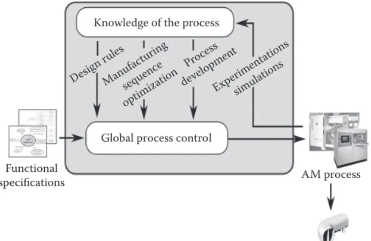
Recent progress has permitted transition from rapid prototyping to AM. Indeed, today, with this kind of manufacturing process, not only prototypes can be produced but also real functional parts in current materials including metals, polymers, and ceramics can be produced [1]. Because AM for production eliminates the need of tooling and can gener-ate free forms, many of the current restrictions of design for manufacturing (DFM) and assembly are no longer valid [2]. However, whatever the technology used [3], as in all the manufacturing processes, the AM ones have characteristics and specificities of their own which may have an impact on the manufactured parts’ quality. In order to utilize the AM possibilities in the best way in terms of design and to ensure the quality of the produced parts, a global numerical chain which allows moving from functional specifications of a part to its manufacturing must be defined (Figure 11.1). The purpose of this numerical chain [4] is to reach a global process control from knowledge of process obtained from experimentations, measurements, and simulations. Among the prerequisite to achieving such numerical chain, a DFM [5] approach is required which allows the AM processes’ capabilities to be taken into account and limits directly from the design stage.
11.1.1 Design for additive manufacturing
Several works have been carried out concerning the classical DFM approach [6] for AM. By concerning manufacturability estimation, manufacturing cost and time have been ana-lyzed [7,8] according to the manufacturing sequence. Similarly, the relationship between parts surfaces quality and manufacturing sequence has been studied [9,10]. From these different specific works, [11] proposed a methodology to map parts in relation to its manu-facturability. Based only on geometrical analysis, these studies are limited because they do not take into account the physical phenomena that occur during the manufacturing
Knowledge of the process
Global process control Functional specifications AM process Manufactured part Design rule s Manuf acturing sequen ce optimi zation Process developmen t Experim entatio ns simulat ions
process [12,13], which may have an impact on parts quality [14] and therefore on their manufacturing time and cost. Concerning manufacturability improvement, there have been very few studies reported on AM processes. General build guidelines have been established [15,16] and a methodology proposed by [17] enables modification of some non-critical geometric features. Moreover, a method for providing mesostructures within a part so as to achieve improved functional requirements part has been established [18]. Here again, the purpose is to minimize fabrication cost and time without a real awareness of the process planning, which do not allow to guarantee the parts quality expected. In addition to these limitations, classical DFM approaches may restrict the new perspectives of design opened up by the AM processes.
11.1.2 Partial approach versus global approach
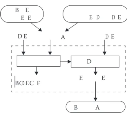
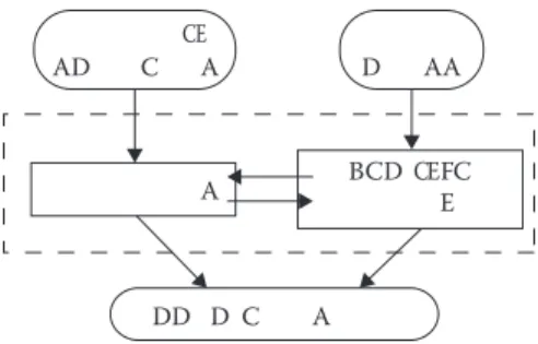
Indeed, all these works enable to determine and to improve the manufacturability of a part from its computer aided design (CAD) model for a given AM process. Because they start from an initial geometry (given by the initial CAD model), these analysis can be qualified as partial approaches (Figure 11.2). In this case, it is difficult to determine the real optimized characteristics for a given AM process while fulfilling original functional specifications. Indeed, the initial CAD model was thought to be manufactured by an initial manufactur-ing process often very different from an AM process (e.g., machinmanufactur-ing which is the most often used); moreover the proposed modifications are local, and the result is never far from the initial design. The CAD model that is obtained is thus never really designed for the AM process that is chosen. On the contrary, a global approach (Figure 11.3) starts directly from both the chosen manufacturing process characteristics and the functional specifica-tions of the parts to design. Designers can thus determine the geometry which optimizes the use of the chosen AM process characteristics while meeting the functional specifica-tions. The purpose is not to limit geometry by an initial idea of the part shapes but to define it only from the manufacturing process and the functional specifications. This new way of thinking is in opposite with traditional DFM methodologies. However, capitaliza-tion of the entire knowledge about the manufacturing processes is needed. A beginning of a global approach, based on topology optimization with manufacturing constraints, has been applied to casting process [19].
B E E E E E E E A D D D D D E E A B B ECCD F
11.1.3 Scope of the paper
Although the global approach seems very interesting, no existing work has been carried out in this way in AM. Because these processes are quite new, still little known and very different from the other manufacturing processes, the psychological inertia phenomena may prevent the designer from utilizing all their capabilities in the best way [20].
Moreover, most of the AM processes are based on a layer-by-layer manufacturing where the material is locally merged, thanks to a local moving energy source (usually a laser or an electron bean) which follows a programmed manufacturing trajectory. It entails that the characteristics of the manufactured volumes, in terms of microstructure [21], geometry [14], and manufacturing time [10] depend first on the manufacturing direc-tion (MD) and secondly on the manufacturing trajectories (MT). In addidirec-tion to the con-sideration of the processes’ characteristics, the choice of the MD and the MT according to functional specifications is thus the key of a global DFAM which would facilitate designers to explore new design spaces. That is why a new methodology which starts directly from both the functional specifications and the process characteristics is proposed in this paper.
First, in Section 11.2, the required data are presented. Then in Section 11.3, the different steps of the methodology, based on the choice of MD, are explained. The methodology has been applied on a part manufactured by a powder-based metal deposition (PBMD) process [22]; this constitutes the fourth section.
11.2 Proposed requirements for a global DFAM
In this section, requirements for a global DFAM are presented. They constitute the required data for the proposed methodology.
11.2.1 Functional specifications
The global purpose is to propose a structured approach which would help the designer to integrate the knowledge of the chosen AM process in his design to meet the functional specifications. The functional specifications can be detailed as follows:
• Functional surfaces (FS): type, dimensions, and position. • Dimensional and geometrical specifications linked to the FS.
• Mechanical requirements: They depend on the chosen material characteristics.
• Empty volumes: dimensions and position. They correspond to the volumes which must not contain material, due to the assembly constraints of the designed part into the system to which it belongs.
A A A DD D C BCD C E AA D C C AD F E C E
11.2.2 Context
The study context is an influential factor. Because it can be translated into a concrete objec-tive in terms of mass, cost, or manufacturing time, it has thus to be taken into account too.
11.2.3 Manufacturing characteristics
Manufacturing characteristics are linked to one another, and they cannot be seen sepa-rately; a global view which draws upon all the knowledge and experience of the com-munity is consequently needed. The main characteristics of the manufacturing machines which must be taken into account are
• Kinematics
• Maximal and minimal dimensions • Capability in terms of accuracy • Required accessibility
But the physical phenomena that are involved in the manufacturing process and which are decisive in terms of final properties of parts, are also linked to the manufacturing sequence.
11.2.4 Finishing process characteristics
Similarly, if specifications (geometrical and dimensional) cannot be directly reached by the AM process that is chosen, a finishing process is needed. Because it can influence the final geometry, particularly in terms of overthickness and required accessibility, it has to be taken into account.
11.3 The proposed design methodology
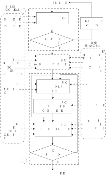
From this data, a structured methodology can help designers in taking into account the manufacturing constraints while suggesting him an appropriate design for AM. The methodology is presented in Figure 11.4. It is divided into three main steps which enable to include gradually manufacturing knowledge in the shapes and the volumes of the parts to be designed. The first step is a global analysis which allows delimiting the design prob-lem in terms of geometrical dimensions in relation to the dimensional characteristics of the AM process. The second one allows to fulfil the dimensional and geometrical specifi-cations in relation to the AM process capability and the finishing process characteristics. Finally, the third step allows to fulfil the physical and assembly requirements in relation to the capability of the AM process.
11.3.1 Step 1: Analysis
The FS are obtained from the functional analysis of the product and are given by the designer. The first methodology step enables to find out if all the surfaces can be merged with one another by the chosen AM process into a single part. A first geometrical analysis is carried out; it takes into account the maximal and minimal dimensions, which can be obtained by the chosen manufacturing machine. If the dimensions are not suitable, the product has to be modified or divided into different parts by the designer, and the func-tional specifications of these new parts are then studied.
11.3.2 Step 2: Determination of the functional volumes
The functional volumes (FV) are defined directly from the FS on to which a thickness is added. Indeed, only the tolerances in the normal direction of the surfaces are significant in terms of functionality. The others are initially ignored. The thickness, denoted E, depends on
• Dimensional accuracy of the AM process denoted a. • Tolerances linked to the FS, denoted p.
D D E E E EE E E E E C C C C EF F F B F F A F F B F F B B B B B B F B F F F B F F F F F F B B A A E C D E E E C C C D C E E E C C E E E E E E E E C D D E E C D E D E C C E E E E E E B C CEEEE E E E E D C D B CD C B D D E E E E E C EE A E D
For each FS, there are two different possibilities: first, if a finishing step is not needed (p ≥ a), thickness is determined from Equation 11.1 which ensures the functional minimal thickness and from Equation 11.2 which ensures the compatibility with the AM process.
E t≥ + a
2 (11.1)
E n d= . −(n−1 α (11.2)). .d
where:
t is the minimal thickness corresponding to the local mechanical requirements. d is the minimal dimension that can be obtained by the chosen AM process. α is the overlap between two adjacent paths.
n is a positive integer.
Equation 11.1 is illustrated in Figure 11.5a. If a finishing step is needed (p < a), then the thickness is determined from Equations 11.2 through 11.4 (Figure 11.5a).
E t≥ + +a e
2 min (11.3)
E t≤ + +a e
2 max (11.4)
where emin and emax are the minimal and maximal overthicknesses, which depend on the finishing process and the surfaces geometry. There can be different values of the parameters d, α, and a (according to the MD).
11.3.3 Step 3: Determination of the linking volumes
The purpose of this step is to merge the FV to define the volumes of the part while tak-ing into account at best both design requirements and manufacturtak-ing constraints. In the
F
(a) D C (b)
B E
EC E E EC A CD
case of AM, volumes are usually obtained layer-by-layer. It involves that their geometries strongly depend on the MD. Indeed, the choices of the MD have a direct influence on mate-rial quantity (need of supports), build time [23], and mechanical properties [24]. Moreover, the MT defining the energy source path during the process have a strong impact on the physical phenomena that occur during the manufacturing process and therefore on the final part quality [25]. That is why, the determination of the MD and MT is at the center of the methodology. The linking volume (LV) definition is divided into four steps. The first step is to determine the most critical MD, which can be characterized by the shape or the number of FV which can be manufactured in the same way. It is carried out according to the study context and the capability of the process given by its kinematics and the physical phe-nomena involved. The second step is, in the chosen MD, to merge the selected FV which can be manufactured from the same substrate. It is carried out according to the empty volumes, which must not be, in the MD, between two FV manufactured from a same substrate. In the third step, the substrates and supports’ shapes are determined according to
• The selected FV. • The other FV.
• The kinematics of the process.
• The accessibility required by the process. • The mechanical requirements.
• The empty volumes. • The study context.
• The physical phenomena that occur during the process.
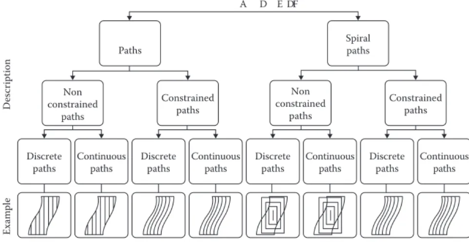
The latter being strongly linked to the type and the shape of the MT that are used, it is essential to select suitable MT among all the possibilities to control them and to guaranty the expected geometrical quality. A classification of the different MT that are possible has been done (Figure 11.6) to describe and parameterize each one of them.
The last step is to check if all the volumes are merged. If it is not the case, the first three steps are repeated while taking into account the FS that have not yet been analyzed and
Non constrained paths Discrete paths Descri ption Exam ple Constrained paths Continuous
paths Discretepaths Continuouspaths Discretepaths Continuouspaths Discretepaths Continuouspaths
Paths Spiralpaths
A D E DF Non constrained paths Constrained paths
the substrates obtained previously, and so on, until all the FV are merged. In the end, the process is complete, and an appropriate design for the chosen AM process is obtained. Indeed, the AM process specifications are taken into account step by step in parallel with the functional requirements. This ensures that the most possible process-related knowl-edge is taken into account to obtain the final shapes of the studied part.
11.4 Example
The proposed methodology has been applied to a case of a robot hinge in stainless steel (Figure 11.7). The study input data are detailed, and the three steps of the DFAM method-ology are illustrated in this section.
11.4.1 Input data
11.4.1.1 Functional specifications
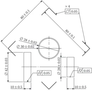
The case is composed of 20 FS: four bearing holders (hollow cylinders) and 16 flat surfaces, which are shown with their nominal dimensions in black in Figure 11.8. To enable the assembly of the case with the other parts of the robot, some empty volumes are defined. They are represented by the transparent volumes.
The functional analysis of the robot has enabled to determine the geometrical and dimensional specifications linked with each surfaces. An extract is shown in Figure 11.9. The mechanical requirements are translated into a final minimal thickness t for each sur-face. It is 5 mm for the hollow cylinders and 3 mm for the based planes.
11.4.1.2 Context
Because of the robotic context, the global objective is to minimize the mass of the studied part. E EF EF ABCD C C
11.4.2 Manufacturing characteristics
11.4.2.1 The additive manufacturing process
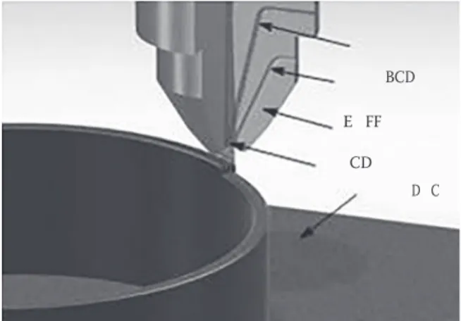
The AM process chosen to manufacture this case is the construction laser additive direct or direct laser additive construction (CLAD) process (Figure 11.10). It is a PBMD pro-cess, based on the 3D layer-by-layer deposition of laser-melted powders. Its main char-acteristics are presented in Table 11.1.
15 ± 0.3 10 ± 0.3 85 ± 0.5
Figure 11.8 The FS and the empty volumes of the part to design.
0.05 0.05 0.05 ∅ 30 ± 0.02 ∅ 42 ± 0.03 ∅ 28 ± 0.02 10 ± 0.5 10 ± 0.5 × 4 80 ± 0.1 80 ± 0.1 ∅ 28 ± 0.02
In this example, the assumptions that parameters d, a, and α are equal in all the directions are made.
The constraints due to the physical phenomena linked with the process (in particular, the thermal phenomena) are considered in ways: first, the substrates’ thickness must be at least equal to the thicknesses of the volumes that it enables to manufacture. Second, because the discontinuities in the MT may generate an unwanted variation of the process parameters and also a gap between the designed and the manufactured part, the geom-etry will be chosen to limit them.
11.4.2.2 The finishing process
The finishing process that is chosen is high-speed milling; in view of the specification related to the FS, this choice involves a minimal and a maximal overthicknesses of 0.5 mm and 1 mm, respectively.
11.4.3 Step 1: Analysis
According to the geometrical analysis of the FS (Figures 11.8 and 11.9) and to the maxi-mal and minimaxi-mal dimensions imposed by the manufacturing process (Table 11.1), all the dimensions are compatible, and all the FS can be merged in only one part.
11.4.4 Step 2: Determination of the functional volumes
The thicknesses E are determined from the different parameters of Equations 11.2 and 11.3; for each FS, the results are given in Table 11.2. All the FV are shown in Figure 11.11a.
BC E CD D C FF D
Figure 11.10 Clad process.
Table 11.1 CLAD process characteristics
Kinematics accessibility (mm)Required dimensions (mm)Maximal d (mm) a (mm) a (mm)
11.4.5 Step 3: Determination of the linking volumes
The MD are determined, due to the robotic context, to minimize the mass of the part and therefore the support structures’ quantity. A geometrical analysis of the FV enables to determine two MD: Z1 and Z2 (Figure 11.11a). Z1 enables to manufacture heighten FV (in dark gray), and Z2 enables to obtain the two last (in light grey). If one or other of the MD is favored (which means that it is analysed in first), the final part geometry could not be the same. Both cases will be therefore analyzed, and the geometry which represented the best way of satisfying the study context will be selected. In case 1, Z1 is favored whereas in case 2, Z2 is favored.
11.4.5.1 Case 1: When Z1 is favored
LVs in Z1 To minimize supports in the empty volumes shown in Figure 11.8 and thus to
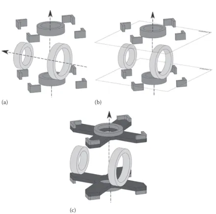
min-imize the finishing operations, all the selected FV linked to Z1 must not be manufactured together but from two different substrates. Their positions are determined (Figure 11.11b)
(b) (a)
(c)
Figure 11.11 Definition of the LV in Z1 when Z1 is favored (a) the FV, (b) position of the substrates,
and (c) the LV geometry in Z1.
Table 11.2 Definition of the FS thicknesses
Surface type t (mm) a (mm) emin (mm) emax (mm) d (mm) E (mm)
Cylinder 5 0.2 0.5 1 0.8 5.9
to minimize supports and time of finishing and to guarantee accessibility for the powder feed nozzle.
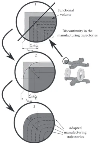
The selected FV geometry is locally modified in relation to the value of emax and emin to minimize the discontinuity of the MT. In particular, in the case of the raster discrete paths, it involves to define a radius R (Figure 11.12), which is given by Equation 11.5:
R=
( )
emax emin( )
− − 2 2 1 .( ) (11.5) Then the geometry of the substrates is defined according to the FV position and their thickness (in black in Figure 11.11c). Because all FV are not merged, a second MD is analyzed.LVs in Z2 As previously discussed, because of the empty volumes, the two cylinders
linked to Z2 cannot be manufactured together. It involves two substrates (Figure 11.13a). Moreover, the space between these FV and those already analyzed (those linked to Z1) being lower than the required one by the powder feed nozzle of the CLAD machine (Table 11.1), the accessibility requirements are not satisfied, and the MD Z2 cannot be used; the process is repeated one more time.
Adapted manufacturing trajectories Discontinuity in the manufacturing trajectories Functional volume 3 2 1 emax emin emax emin R R
LVs in Z3 A third MD Z3 is determined from the previous substrates (linked to Z1) and FV (Figure 11.13b). The substrate and supports linked to Z3 are determined, as previously, due to the context, to minimize the material quantity and to avoid, as much as possible, the empty volumes. The substrate dimensions are given by the volumes that it merges. The supports geometry are simply defined by the orthogonal projection of the volumes linked to Z3 onto the substrate (Figure 11.13c). Finally, all the FV are merged, the design process is then complete, and the final blank part is obtained.
11.4.5.2 Case 2: When Z2 is favored
From the FV in Figure 11.11a, the same reasoning is applied, starting with the analyzed Z2.
LVs in Z2 In the same way as above, because of the empty volumes, the two cylinders
linked to Z2 cannot be manufactured together. Two substrates whose geometry is shown in black in Figure 11.14a are therefore defined.
LVs in Z1 Similarly, all the FV linked to Z1 cannot be manufactured together. First, as
in the case where Z1 was favored, to minimize supports in the empty volumes, a minimum of two separated substrates is needed. Moreover, because of the manufacturing of the cyl-inders linked to Z2, the accessibility required by the powder feed nozzle involves that each one of these two substrates has to be subdivided once again into tree-separated substrates. In the same way as previously, the geometry of the FV linked to Z1 is locally modified in relation to the value of emax and emin, and then the substrates’ geometry is defined (in black in the Figure 11.14b).
(a) (b)
(c)
Figure 11.13 Definition of the LV in Z2 and Z3, when Z1 is favored (a) position of the substrates in
New LVs in Z2 As all the FV are not merged, another MD should be, thus, analyzed. Because of the accessibility requirement, all the substrates previously obtained cannot be merged to one another following only one MD. Z2, being already selected and allow-ing to merge again several volumes of the part, is reanalyzed. The result is shown in
Figure 11.14c.
LVs in Z3 Because all the FV are still not merged, the design process is repeated once
again. All the previous substrates (defined in Z2 and Z1) can be merged into a third MD: Z3. The substrate position and geometry are determined; then the supports are defined by the orthogonal projection of the volumes linked to Z3 onto the substrate (Figure 11.14d).
Finally, all the FV are merged; the design process is thus complete, and the final blank part is obtained.
11.4.6 Final result
Thanks to the proposed methodology, each shape of the part has been designed in order to utilize the CLADő process characteristics and capabilities to fulfil the study functional specifications while taking into account its general context. In the initial stage, from the geometrical analysis of the FS and according to the objective of minimizing the final part mass, two MDs have been selected (Z1 and Z2). Because the favoring of the one or other may have an impact on the final part geometry, the two cases have been studied. The
(a)
(c) (d)
(b)
Figure 11.14 Definition of the different LV, when Z2 is favored (a) the LV geometry in Z2, (b) the LV
final results, obtained after considering the finishing operation which enables to meet the required specifications (geometrical and dimensional) and to remove the material in the empty volumes, are shown in Figure 11.15. A finite element method analysis has been done to simulate the mechanical behavior of the proposed designs under the robot normal condition of use. Because, the results are quite close to each other compared with the mate-rial limits, they do not really enable to make a choice between both proposed solutions. However, as it is shown in Table 11.3, the favoring of Z2 over Z1 results in a lower mass of the blank part (around 19%) and of the finished part (around 9%). It allows, therefore, a lower manufacturing cost and to meet the global objective given by the robotic context of the study better. This solution is thus finally selected.
11.5 Conclusion
This paper described the initial stage of a promising research project which deals with a global DFAM approach. A new methodology is proposed to obtain an appropriate design for AM processes. In contrary to the classical DFM approaches, to prevent the psychologi-cal inertia phenomena which may limit the design innovation and to best utilize the AM processes’ capabilities, the proposed methodology starts directly from both functional specifications and AM processes’ characteristics. The required data for such a global DFAM approach have been presented. Then the three steps of the methodology allowing to reach to take into account all of them has been detailed and illustrated by a case study taken from the robotic field.
Further research will be conducted to optimize the methodology in particular regard-ing the local optimization of the shapes and the internal structures of the LVs in terms of functionality as it is done, for example, by [26]. In parallel, new criteria of choice for
(a) (b)
Figure 11.15 The final geometry: (a) when Z1 is favored and (b) when Z2 is favored.
Table 11.3 Characteristics of the two prosed solutions When Z1
is favored
When Z2
is favored Blank part mass (g) 775.9 627.5 Finished part mass (g) 548.6 499.0 Maximal von-Mises stress (MPa) 15.3 22.6 Maximal displacement (mm) 0.041 0.015
MT will be developed to always adapt the local geometry more regarding the physical phenomena which occur during the manufacturing process.
References
1. P. Mognol, P. Muller, and J. Y. Hascoet. A novel approach to produce functionally graded mate-rials for additive manufacturing. In Proceedings of the Conference on Advanced Research in Virtual
and Rapid Prototyping, CRC Press, Leiria, Portugal, 2011.
2. E. Pessard, P. Mognol, J. Y. Hascoët, and C. Gerometta. Complex cast parts with rapid tool-ing: Rapid manufacturing point of view. The International Journal of Advanced Manufacturing
Technology, 39(9–10):898–904, 2007.
3. T. Wohlers. Wohlers report: Additive Manufacturing State of the Industry. Wohlers associates, Fort Collins, CO, 2010.
4. R. Bonnard, P. Mognol, and J. Y. Hascoët. A new digital chain for additive manufacturing processes. Virtual and Physical Prototyping, 5(2):75–88, 2010.
5. S. K. Gupta, W. C. Regli, D. Das, and D. S. Nau. Automated manufacturability analysis: A survey.
Research in Engineering Design, 9(3):168–190, 1997.
6. S. A. Shukor, and D. A. Axinte. Manufacturability analysis system: Issues and future trends.
International Journal of Production Research, 47(5):1369–1390, 2009.
7. P. Alexander. Part orientation and build cost determination in layered manufacturing.
Computed-Aided Design, 30(5):343–356, 1998.
8. M. Ruffo, C. Tuck, and R. Hague. Cost estimation for rapid manufacturing laser sintering pro-duction for low to medium volumes. Journal of Engineering Manufacture, 220(9):1417–1427, 2006. 9. R. Arni, and S. K. Gupta. Manufacturability analysis of flatness tolerances in solid freeform
fabrication. Journal of Mechanical Design, 123(1):148, 2001.
10. M. Anca˘u, and C. Caizar. The computation of Pareto-optimal set in multicriterial optimization of rapid prototyping processes. Computers & Industrial Engineering, 58(4):696–708, 2010.
11. O. Kerbrat, P. Mognol, and J. Y. Hascoet. Manufacturability analysis to combine additive and subtractive processes. Rapid Prototyping Journal, 16(1):63–72, 2010.
12. X. He, and J. Mazumder. Transport phenomena during direct metal deposition. Journal of
Applied Physics, 101(5):053113, 2007.
13. S. Y. Wen, Y. C. Shin, J. Y. Murthy, and P. E. Sojka. Modeling of coaxial powder flow for the laser direct deposition process. International Journal of Heat and Mass Transfer, 52(25–26):5867– 5877, 2009.
14. M. Alimardani, E. Toyserkani, and J. Huissoon. A 3D dynamic numerical approach for temper-ature and thermal stress distributions in multilayer laser solid freeform fabrication process.
Optics and Lasers in Engineering, 45(12):1115–1130, 2007.
15. S. Filippi, and I. Cristofolini. The Design Guidelines (DGLs), a knowledge-based system for industrial design developed accordingly to ISO-GPS (Geometrical Product Specifications) con-cepts. Research in Engineering Design, 18(1):1–19, 2007.
16. G. A. Teitelbaum. Proposed Build Guidelines for Use in Fused Deposition Modeling to Reduce
Build Time and Material Volume. Master of Science in Mechanical Engineering, University of Maryland, College park, MD 2009.
17. S. Sambu, Y. Chen, and D. W. Rosen. Geometric tailoring: A design for manufacturing method for rapid prototyping and rapid tooling. Journal of Mechanical Design, 126(4):571–580, 2004. 18. D. W. Rosen. Computer-aided design for additive manufacturing of cellular structures.
Computer-Aided Design & Applications, 4(5):585–594, 2007.
19. L. Harzheim, and G. Graf. A review of optimization of cast parts using topology optimization part II. Structural and Multidisciplinary Optimization, 31(5):388–399, 2005.
20. R. Hague. Unlocking the design potential of rapid manufacturing. In Rapid Manufacturing:
An Industrial Revolution for the Digital Age, Loughborough University, Loughborough, UK, 2006.
21. L. Costa, R. Vilar, T. Reti, and A. Deus. Rapid tooling by laser powder deposition: Process simulation using finite element analysis. Acta Materialia, 53(14):3987–3999, 2005.
22. J. Ruan, T. E. Sparks, Z. Fan, J. K. Stroble, and A. Panackal. A review of layer based manufactur-ing processes for metals. In Proceedmanufactur-ings of the Seventeenth Solid Freeform Fabrication Symposium, Austin, Texas, USA, pp. 233–245, 2006.
23. P. Singh, and D. Dutta. Multi-Direction slicing for layered manufacturing. Journal of Computing
and Information Science in Engineering, 1(2):129, 2001.
24. B. Caulfield, P. E. McHugh, and S. Lohfeld. Dependence of mechanical properties of polyamide components on build parameters in the SLS process. Journal of Materials Processing Technology, 182(1–3):477–488, 2007.
25. E. Foroozmehr, and R. Kovacevic. Effect of path planning on the laser powder deposition pro-cess: Thermal and structural evaluation. The International Journal of Advanced Manufacturing
Technology, 51(5–8):659–669, 2010.
26. H. De Amorim Almeida, and P. Jorge Da Silva Bártolo. Virtual topological optimisation of scaffolds for rapid prototyping. Medical Engineering & Physics, 32(7):775–82, 2010.