HAL Id: hal-01008547
https://hal.archives-ouvertes.fr/hal-01008547
Submitted on 8 Jul 2018HAL is a multi-disciplinary open access archive for the deposit and dissemination of sci-entific research documents, whether they are pub-lished or not. The documents may come from teaching and research institutions in France or abroad, or from public or private research centers.
L’archive ouverte pluridisciplinaire HAL, est destinée au dépôt et à la diffusion de documents scientifiques de niveau recherche, publiés ou non, émanant des établissements d’enseignement et de recherche français ou étrangers, des laboratoires publics ou privés.
Numerical modeling of material flow with an internal
length
Frédéric Dufour, Gilles Pijaudier-Cabot
To cite this version:
Frédéric Dufour, Gilles Pijaudier-Cabot. Numerical modeling of material flow with an internal length. 17th ASCE Engineerings Mechanics Conference, Jun 2004, Newark, United States. �hal-01008547�
NUMERICAL MODELING OF MATERIAL FLOW WITH AN INTERNAL LENGTH
F. Dufour1and G. Pijaudier-Cabot2
ABSTRACT
In this paper we propose a new numerical method to study material flow with an internal length. The finite element method with Lagrangian interpolation points (FEMLIP) is used for its capability to model large deformation processes for any type of materials. It is widely accepted in the litterature that fresh concrete rheology is very well estimated by Bigham model in the classical continuum approach. Nevertheless in most cases the form size and the distance between reinforced bars are about few times greater than aggregate size itself. This means that the microstructure has a non negligible effect on the flow (aggregate rotation independent of material rotation + boundary layer effect) and that it must be taken into account to get a good estimation of the filling capability of the material. We propose to use a Cosserat continuum with a Bingham law to tackle this work.
Keywords:Cosserat model, Bingham rheology, fresh concrete flow. INTRODUCTION
The objectives of this work are to model heterogeneous two-phase fluid like fresh concrete flow during filling form processes with a particular concern about aggregate segregation and/or locking effect around reinforced bars. The aggregate mean size is only few times smaller than the distance between the bars or between the bars and the mould. Therefore, microstructure must be taken into account to get a good estimation of the concrete flow and boundary condi-tions must be addressed carefully.
We already have modelled (Dufour, 2002) concrete flow either with an homogeneous or an heterogeneous approach within the classical continuum framework. In the first approach, informations about material microstructure are clearly missing (e.g. material locking between bars cannot be modelled) whereas the second approach is very much demanding on computer ressources and cannot be used for large scale applications.
Therefore, we propose in this work to combine the Bingham model with a Cosserat contin-uum in order to enhance microstructure effects into the model without having to use very fine and numerically costly meshes. We wish to avoid as much as possible heterogeneous modelling for large scale problems because of memory and computational time limits. Along these lines, heterogeneous modelling will be used only for validations purposes.
1
Corresponding author: ERT R&DO, Institut de Recherche GeM, Ecole Centrale de Nantes, 1 rue de la no¨e, 44321 Nantes, FRANCE, e-mail: [email protected]
2
NUMERICAL METHOD
To tackle these objectives, we use a finite element method with Lagrangian interpolation points (FEMLIP) implemented in our ellipsis code (Moresi et al., 2002) where the problem domain is represented by an Eulerian mesh with an embedded set of Lagrangian integration points or particles. Unknowns (i.e. velocity field) are computed at the mesh nodes and the Lagrangian particles carry history variables during the large deformation process including material properties. This method is ideally suited to model fluid-like behavior of continuum solids like two-phase fluid. From the material properties point of view, unlike in a pure Eulerian method, material interfaces do not show convection during computations as fictitious lines representing interfaces are preserved during flow between two adjacent particles with different properties. From the computational point of view, interfaces are taken into account in one finite element for which rheological properties are averaged for integration. The consequence is that the modelling of heterogeneous material needs very fine meshes with the FEMLIP same as for any numerical method based on integration over volumes.
RHEOLOGICAL LAWS
Concrete, in its fresh state, can be considered as a homogeneous fluid, provided that a certain degree of flow can be achieved and that the mix is quasi-homogeneous with regularly dispersed aggregate particles (in space and size). Modelling concrete rheology is a very difficult task as every concrete behaves differently depending on their composition and mixing method. Therefore it is impossible to write a relation between the stress and the strain rate based on every single parameter at the microscale, quantities and nature of each admixtures in particular, which are nowadays more and more numerous. Here, the concrete rheology is thought at a mesoscale and it is written as a relation between the shear stress τ and the shear strain rate ˙γ. A complete review of rheological models for cement based materials has been done by Yahia and Khayat (2003). We discuss here only the three simplest ones, namely Newton’s, Bingham’s and Herschel-Bulkley’s models.
The simplest model (one parameter) assumes that concrete is a Newtonian fluid:
τ = η ˙γ (1)
where η is the viscosity but Tatersall (1973) has shown that a single parameter is not enough to model concrete flow. At least two parameters are needed to model concrete with a slump lower than 30 cm. The first one needs to be related to the static behaviour (slump test) and the second one to the dynamic fluid response (rheometer test). Hence, a stress threshold has been added to the Newton’s model to give the Bingham’s model:
τ = τ0+ η ˙γ if τ ≥ τ0 (2)
˙γ = 0 if τ ≤ τ0 where τ0is the yield stress and η is the plastic viscosity.
When experimental data are fitted for many different concretes and for self-compacting concrete especially, it often yields a negative value of the yield stress although very small. For this reason de Larrard et al. (1998) prefered to use a Herschel-Bulkley’s model (3 parameters):
τ = τ00+ a ˙γb (3)
Ferraris and de Larrard (1998) have found a mean value for b of 1.53 for concrete without superplasticizer and 1.36 for others. However the Bingham’s model (e.g. b = 1) is most widely
used (Tsong et al., 1999) because it needs less experimental tests to be calibrated. For the same reason, we have chosen to use the Bingham’s model in this study.
One example for each rheological model is plotted in Figure 1.
4 5 6 0 1000 2000 3000 4000 Strain rate (s-1)
Shear stress (Pa)
(a) (b) (c) 3 2 1 0
FIG. 1. Different rheological models for fluid-like materials. (a) Newton (η = 650Pa.s), (b) Bingham (τ0 = 500Pa,η = 500Pa.s) and (c) Herschel-Bulkley (τ00 = 400Pa, a = 500
Pa.sb andb = 1.2).
For an easier numerical implementation, the Bingham’s model needs to be smoothed (Pa-panastasiou, 1987) in order to avoid the corner at τ = τ0 on the material response and the use
of two equations under and above the shear stress threshold. This yields: η = η0+τ˙γ0
¡
1 − e−m ˙γ¢ (4)
where m is the stress growth rate parameter. The higher m, the more accurate the approxima-tion. We found out, for the range of strain rates reached during our numerical tests, that a value m=5000 is high enough as we observed no differences with results obtained with a value of m=10000.
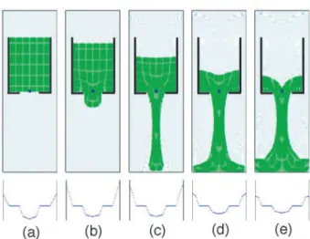
(Dufour and Pijaudier-Cabot, 2004) have already shown the ability of this rheological law together with the FEMLIP to model concrete flow during slump test (Fig.2) and Lbox filling (3).
The use of Bingham’s law in for a classical continuum needs two different types of exper-imental tests. The first one, the slump test, to identify the yield stress and the second one, a rheometer test, to identify the plastic viscosity. For the rheometer test we have chosen to mea-sure the flow time of fresh concrete in a funnel. The reason is that it can be easily modelled by ellipsis as the flow is nearly 2D.
ENHANCED MODEL
In a 2D conventional continuum the deviatoric part of an isotropic material is characterised by a shear viscosity η. For a Cosserat continuum we also have a Cosserat shear viscosity ηc and a bending viscosity M . The constitutive relation for a generalised Newtonian fluid can be
(a) (b)
(c)
(d)
FIG. 2. Different snapshots of slump test on SCC at time 0 s. (a), 0.36 s. (b), 1.87 s. (c) and 7.24 s. (d).
(a)
(d) (c)
(b)
FIG. 3. Different snapshots of the Lbox test on SCC at time 0 s. (a), 0.45 s. (b), 0.85 s. (c) and 7.63 s. (d).
written in the usual pseudo-vector form:
τ = ΛD (5)
where τ is the deviatoric stress vector and the matrix Λ is expressed as: η η 0 0 0 0 η 0 0 0 0 η + ηc η − ηc 0 0 η + ηc 0 0 symm. M 0 M (6)
It means that when the Bingham’s law for a Cosserat continuum is implemented two ad-ditional parameters are required. Choi and M¨uhlhaus (1991) have proposed relations between bending viscosity and viscosity η and internal length d such as:
M = 2ηd (7)
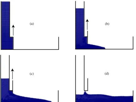
If we assume that the internal length of such a material is the granular size, then only one more parameter needs to be identified. One example of behaviour of this Cosserat continuum is studied for Newtonian material. We consider the discharge of a Cosserat material from a model silo (Fig.4). In this case we are interested in the influence of the internal length parameter on the discharge velocity (Fig.5) of a Cosserat fluid as described by (5–6)
FIG. 4. Snapshots of the model. (a) Initial conditions, (b) t = 4.75 10−4 sec.,
(c) t = 1.42 10−3 sec., (d) t = 2.85 10−3 sec. and (e) t = 3.8 10−3sec.. The plot
below each picture corresponds to the vertical velocity profile throughout the silo aperture.
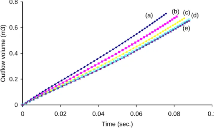
In Fig. 5 we plot the volume flowing out the reservoir versus time and for different values of the ratio α = d/a where a is the silo aperture and d is the internal length of the material. The flow rate is almost identical for all values of α (Fig. 5-d and 5-e) larger than the aperture (1.0) which corresponds, in the elastic case, to a situation in which no flow can occur. Note that in purely viscous materials static equilibrium states do not exist, ensuring that stable arches do not form. For 0 ≤ α ≤ 1.0, the smaller the internal length the faster the outflow. Indeed Dufour et al. (2001) have observed the same effects in the case of an infinite shearlayer. The first effect is a boundary layer effect along the boundaries. Here is a possibility to force the material rotation to zero for non spherical aggregates which can slide without rotating. The second effect is that for the same body force, a Cosserat fluid will flow slower than a classical one because energy is stored within the material due to bending stiffness. Frictional contacts between aggregates are modeled by Cosserat couple stresses.
BINGHAM’S FLOW WITHIN A COSSERAT CONTINUUM
To get the microstructure description of a Cosserat model together with the Bingham rhe-ology we propose to model Bingham’s flow within a Cosserat continuum. In the Cosserat constitutive matrix the viscosity η can be identified to the Bingham’s viscosity, ηc and M
0 0.2 0.4 0.6 0.8 0 0.02 0.04 0.06 0.08 0.1 Time (sec.) Outflow volume (m3) (a) (b) (c)(d) (e)
FIG. 5. Outgoing volume for (a)α=0, (b)α=1/3, (c)α=2/3, (d)α=5/3 and (e)α=10/3
needs to be identified. The first term is a constant fraction of the Bingham’s viscosity and the second one is calculated as a function of the internal length taken equal to the granular size D50. The coupling of the Bingham’s law with a Cosserat model allows the use of coarser
mesh with a homogeneous fluid approach compared to the modelling of heterogeneous fluid. The microstructure effect is brought into equations instead of the geometry. This coupling will be used in the future whenever boundary layer effects are of importance in the concrete flow for instance in the Lbox problem or in order to study concrete flow in the casting of densely reinforced strutural elements.
REFERENCES
Choi, S. K. and M¨uhlhaus, H.-B. (1991). Distinct elements vs Cosserat theory: A comparison for the case of an infinite shearlayer, 315–319. Eds. Beer, Booker and Carter.
de Larrard, F., Ferraris, C. F., and Sedran, T. (1998). “Fresh concrete : a herschel-bulkley material.” Materials and Structures, 31(211), 494–498.
Dufour, F. (2002). “D´eveloppements de la m´ethode des ´el´ements finis avec des points d’int´egration lagrangiens : Application `a la g´eom´ecanique,” PhD thesis, Ecole Centrale de Nantes.
Dufour, F., M¨uhlhaus, H.-B., and Moresi, L. (2001). “A particle-in-cell formulation for large deformation in cosserat continua.” Bifurcation and Localization Theory in Geomechanics, H.-B. M¨uhlhaus, A. Dyskin, and E. Pasternak, eds., Lisse. Swets & Zeitlinger, 133–138. Dufour, F. and Pijaudier-Cabot, G. (2004). “Numerical modelling of concrete flow:
homoge-neous approach.” International Journal for Numerical and Analytical Methods in Geome-chanics. submitted.
Ferraris, C. F. and de Larrard, F. (1998). “Testing and modelling of fresh concrete rheology.” NISTIR 6094, 59 p.
Moresi, L., Dufour, F., and M¨uhlhaus, H.-B. (2002). “Mantle convection models with vis-coelastic/brittle lithosphere: Numerical methodology and plate tectonic modeling.” Pure & Applied Geophysics, 159, 2335–2356.
Papanastasiou, T. C. (1987). “Flows of materials with yield.” Journal of Rheology, 31, 385– 404.
Tatersall, G. (1973). The rationale of a two-point workability test, Vol. 25.
Tsong, Y., Chao-Wei, T., Chao-Shun, C., and Kuang-Hong, C. (1999). “Flow behaviour of high strength high-performance concrete.” Cement and Concrete Composites, 21(5-6), 413–424. Yahia, A. and Khayat, K. (2003). “Applicability of rheological models to high-performance
grouts containing supplementary cementitious materials and viscosity enhancing admix-ture.” Materials and Structures, 36, 402–412.