En vue de l'obtention du
DOCTORAT DE L'UNIVERSITÉ DE TOULOUSE
Délivré par :Institut National Polytechnique de Toulouse (Toulouse INP)
Discipline ou spécialité :
Dynamique des fluides
Présentée et soutenue par :
M. THOMAS KAISER le jeudi 31 janvier 2019
Titre :
Unité de recherche : Ecole doctorale :
Impact of Flow Rotation on Flame Dynamics and Hydrodynamic Stability
Mécanique, Energétique, Génie civil, Procédés (MEGeP) Institut de Mécanique des Fluides de Toulouse (I.M.F.T.)
Directeur(s) de Thèse :
M. THIERRY POINSOT M. LAURENT SELLE
Rapporteurs :
M. PASCAL BRUEL, CNRS
M. RONAN VICQUELIN, CENTRALESUPELEC GIF SUR YVETTE
Membre(s) du jury :
M. JEAN-MARC CHOMAZ, CNRS PARIS, Président
M. KILIAN OBERLEITHNER, TECHNISCHE UNIVERSITAT BERLIN, Membre M. MATTHEW JUNIPER, UNIVERSITE DE CAMBRIDGE, Membre
M. THIERRY POINSOT, CNRS TOULOUSE, Membre
Wohltätig ist des Feuers Macht,
Wenn sie der Mensch bezähmt, bewacht, Und was er bildet, was er schafft,
Das dankt er dieser Himmelskraft. Auszug aus Das Lied von der Glocke
- Friedrich Schiller
Most wholesome is the force of fire, When man can tame and guard its ire, And from this heavenly force man takes Good help for what he moulds and makes. Excerpt from The song of the bell
- Friedrich Schiller
Acknowledgements
In his poem The song of the bell (see excerpt on the preceding page) the German poet Friedrich Schiller describes the 18th century manufacturing process of a church bell from creating the casting mold until its first stroke. The main focus of the poem is on the human creative urge and his will to “mould” and “make”. And of course especially on the feelings and sentiments that are inherent to the creative process: Joy in creating, passion and diligence, but also despair, fear, loss of control. And finally the feeling of uncertainty, just before the casting mold is broken and the bell arises from the dust. To the authors knowledge, it is unknown if Friedrich Schiller, himself a doctor of medicine and law, was inspired to his poetic masterpiece by his own dissertation and he changed the story line to a manufacturing process in order to make it appealing to a broader audience.
The song of the bell however barely describes one aspect, which probably invokes the most positive sentiments during a creative process: The companions of the creative, be they directly or indirectly involved in the project. Without them it would not only be less joyful, it would be impossible. Similarly, in theses, as they are naturally focused on the results of the work, the appreciation for colleagues, supervisors, family and other supporters cannot be sufficiently expressed. This short text cannot compensate all the help that I received from my companions along this journey during the last three years and before. In fact nothing can. This nevertheless is the attempt to at least give them the stage and laurels they deserve. One person however is mentioned in The song of the bell: It is the master (today called supervisor), who after the dangerous casting process counts the heads of his team and finds in relief that everyone was spared. In my case this role fell onto two persons. Firstly, I would like to thank my first supervisor Thierry Poinsot. Thank you for having trust in me and creating a research environment in which I could follow my research freely. It is impressive how accurately you know, at what moments you have to increase or decrease the pressure on a doctoral student to help him being optimally motivated. Furthermore, I would like to thank Laurent Selle, my co-supervisor. Your active support has helped me to meet the one or other deadline. Also the fact that you are an inexhaustible source of ideas is well known beyond the boarders of Toulouse. This trait of yours often helped me to find new perspectives on organizational and scientific problems. By working with the two of you I had
the possibility to learn countless lessons, which are not only restricted to my professional life. Thank you!
Beyond, I would like to thank Kilian Oberleithner, who helped me taking first steps in hydrodynamic stability analysis. Working with you was not only an immense professional benefit, due to your uncomplicated, down to earth character it was also always a pleasure. Also the collegiality of the whole research team at TU Berlin during my two months stay is gratefully acknowledged. I am glad, that I will have the opportunity to continue my work together with you in Berlin.
I am also grateful towards the reviewers of my doctoral thesis, Pascal Bruel and Ronan Vicquelin and jury members in my defense: Kilian Oberleithner, Jean-Marc Chomaz and Matthew Juniper. I am glad that you are taking the time to read my dissertation and come to my defense in Toulouse.
Thousand thanks also go to my great office mates, Quentin and Christian, and later Dominik and Jimmy. Thank you for all the valuable discussions about work and beyond. Of course my gratitude goes beyond my office doors to all my friends in the (former) Particle Spray and Combustion team at IMFT. When I came to Toulouse, I always felt welcomed in the group, both during and after work. Namely, I would like to mention in this context Maxence, Guillaume, Corentin and Emilien who altogether kicked me off into the numerical combustion world of Toulouse. Furthermore, I would like to thank our combustion experiment team, Daniel, Pradip and Görkem, for providing the valuable experimental data. I thank Abdulla, for his professional support but - in fact especially - for giving me an unforgettable first impression of CERFACS, Aynur for uplifting words not only but also after bicycle accidents and Francois for giving shelter to the homeless.
Without the support of the CFD group at CERFACS, our numerical work at IMFT would have been much harder. In the context of my own work I received valuable help from Gabriel Staffelbach. Thank you for answering all my naive and not naive questions about AVBP. How you manage to keep up with your work load remains a mystery to outsiders.
A special place in these acknowledgements is reserved for my family. Without the uncon-ditional support of my parents, Ludwig and Maria-Theresia, not only this dissertation but much more than that would have been inconceivable. You never let any stone unturned to provide me with all possibilities for my education and clear my way. I am aware what a privilege it is to be born by coincidence in the situation to have parents like you. My gratitude towards you goes beyond what I can express with words. Therefore, this thesis is dedicated to you. Furthermore, I am grateful for the priceless help of my brother Marcus. You were not only a big brother but also a role model to me in the academic world. And that is even though I never really understood what you are doing. Yet, I am relieved that it is the same the other way around. Finally, I would like to thank my girlfriend Anna, who did her studies in Munich while I was in Toulouse for my dissertation. I know, it is not easy
to have a boyfriend who constantly thinks about strange equations and at the same time is often far away for several months. Therefore, I thank you for your patience and I cannot express how happy I am that we mastered this difficult challenge.
Abstract
This thesis investigates large scale flow rotation in two configurations. In the first, the focus is on the effect of flow rotation on a laminar flame. The flame is anchored in the wake of a cylindrical bluff body. The flow rotation is introduced by turning the cylinder along its axis. It is shown by Direct Numerical Simulation (DNS), that the cylinder rotation breaks the symmetry of both flame branches. Flame Transfer Function (FTF) measurements performed by the Wiener-Hopf Inversion suggest, that low rotation rates lead to deep gaps in the gain and the flame becomes almost insensitive to acoustic perturbation at a specific frequency. It furthermore is demonstrated that this decrease in gain of the FTF is due to destructive interference of the heat release signals caused by the two flame branches. The frequency at which the gain becomes almost zero can be adjusted by tuning the cylinder rotation rate. The study suggests that controlling the symmetry of the flame could be a tool of open-loop control of thermoacoustic instabilities.
In the second configuration the cause of flow rotation is a hydrodynamic instability, namely the Precessing Vortex Core (PVC) in an industrial fuel injection system. Experimental measurements and Large Eddy Simulation (LES) show that the non-reacting flow within the primary injector is superimposed by a PVC. The hydrodynamic instability furthermore is investigated by a Linear Stability Analysis (LSA). Both local an BiGlobal approaches are applied and compared regarding their respective results. Experimental, LES and LSA results demonstrate that mounting a central rod in the interior of the primary injector stabilizes the PVC. In addition, the same industrial injector is investigated for a reacting flow via LES. The results demonstrate, that the flame stabilizes the flow concerning the PVC. It is shown by a BiGlobal stability analysis, that the density gradient in the mean flame front has a significant dampening effect on the instability. Finally, the impact of the central rod is investigated also for reacting flows. It is shown, that the central rod only marginally effects the global flame shape, but has a beneficial effect on flame anchoring in the lean regime. Both cases, the one with rod and the one without rod are compared also by a LSA concerning the stability of the PVC. Results suggest, that the rod significantly increases the dampening of the PVC. This could lead to decreased turbulence levels in the flow, prevent flame quenching and therefore explain the beneficial influence of the rod regarding flame anchoring.
Résumé
Cette thèse a pour but l’étude de la rotation de l’écoulement des grandes échelles dans deux configurations. La première configuration se concentre sur l’effet de la rotation de l’écoulement sur une flamme laminaire. Elle est stabilisée dans le sillage d’un cylindre. La rotation de l’écoulement est introduite en faisant tourner le cylindre autour de son axe. La simulation numérique directe (Direct Numerical Simulation (DNS)) montre que la rotation du cylindre rompt la symétrie des deux branches de la flamme. La fonction de transfert de flamme (Flame Transfer Function (FTF)), obtenue grâce à l’inversion de Wiener-Hopf, indique qu’un faible taux de rotation réduit le gain de la FTF et donc la flamme devient presque insensible aux perturbations acoustiques à une fréquence donnée. De plus, il est démontré que cette diminution du gain est due à une interférence destructive des fluctuations de chaleur produites par les deux branches de la flamme. La fréquence à laquelle le gain de la FTF devient presque nul est ajustable par la vitesse de rotation du cylindre. Cette étude suggère que le contrôle de la symétrie de la flamme pourrait être un outil de contrôle en boucle ouverte des instabilités thermoacoustiques.
Dans le cas de la deuxième configuration, la rotation de l’écoulement est induite par une instabilité hydrodynamique, aussi nommée Precessing Vortex Core (PVC) dans un système d’injection de carburant industriel. Des expériences et des simulations aux grandes échelles (Large Eddy Simulation (LES)) montrent que l’écoulement non-réactif dans l’injecteur pri-maire peut être décomposé en une contribution moyenne et un PVC. Cette instabilité hydro-dynamique est étudiée par l’analyse de stabilité linéaire (Linear Stability Analysis (LSA)) en utilisant deux approches différentes (locale et BiGlobale). Les résultats de l’expérience, de la LES et de la LSA démontrent que le montage d’une tige centrale à l’intérieur de l’injecteur stabilise le PVC. De plus, le même injecteur industriel est étudié dans le cas d’un écoule-ment réactif par LES. Les résultats démontrent que la flamme stabilise le PVC. L’analyse de stabilité BiGlobal montre que le gradient de densité dans le front moyen de la flamme a un effet important sur l’amortissement du PVC. Enfin, l’impact de la tige centrale est également étudié pour le cas réactif. La tige centrale impacte marginalement la forme globale de la flamme, mais a un effet positif sur l’accrochage de la flamme dans la zone de combustion pauvre. En comparant deux cas par LSA, celui avec la tige et celui sans la tige, les résultats suggèrent que la tige augmente considérablement l’amortissement du PVC. Cela pourrait
causer une diminution de la turbulence dans l’écoulement et empêcher l’extinction de la flamme et donc expliquer l’influence bénéfique de la tige sur la stabilisation de la flamme.
Contents
List of Symbols xxv
Abbreviations xxix
1 Introduction 1
1.1 Combustion - A Future Technology? . . . 1
1.2 Fundamentals of Thermoacoustics . . . 6
1.2.1 On the Cause and Nature of Thermoacoustic Instabilities . . . 6
1.2.2 Analysis Tools for Thermoacoustic Instabilities in Combustion Systems 9 1.2.2.1 Brute-Force Time Integration of the Full Set of Reactive Navier-Stokes Equations . . . 9
1.2.2.2 Isolation of Physical Phenomena by Low(er) Order Approaches 10 1.3 Impact of Flow Rotation on Flame Dynamics . . . 11
1.4 Objectives . . . 13
I
Symmetry Breaking by Flow Rotation: Impact on the
Ther-moacoustic Behaviour of Laminar Flames
17
2 DNS Tools 19 2.1 Governing Equations . . . 202.1.1 Perfect Gas Law . . . 20
2.1.2 Continuity Equation . . . 21
2.1.3 Momentum Equations . . . 22
2.1.4 Energy Equation . . . 22
2.2 Numerical Discretization . . . 23
2.2.1 The Cell Vertex Method . . . 23
2.2.2 Convection scheme . . . 24
2.3 Chemistry Model . . . 25
CONTENTS
3.1 Experimental Set-Up . . . 29
3.2 Simulation Setup and Meshing . . . 30
3.3 Results of Laminar DNS . . . 33
3.3.1 Steady State Response to Bluff Body Rotation . . . 33
3.3.2 Flame Response to Acoustic Forcing . . . 36
3.3.2.1 System Identification: The Wiener-Hopf Inversion . . . 36
3.3.2.2 Flame Response without Rotation . . . 40
3.3.2.3 Flame Response with Rotation . . . 48
3.3.2.4 Influence of Bluff Body Rotation on Flame Front Dynamics 53 3.4 Conclusion . . . 55
II
Hydrodynamic Instabilities in Fuel Injection Systems
57
4 LES 59 4.1 LES Governing Equations . . . 604.2 Turbulence Modelling . . . 62
4.3 LES Chemistry Model . . . 63
4.3.1 BFER . . . 63
4.3.2 Thickened Flame Model . . . 64
5 Linear Stability Analysis of Hydrodynamic Instabilities 65 5.1 Governing Equations of Hydrodynamic Stability . . . 66
5.1.1 Coherent Structures in Uniform Density Flows . . . 67
5.1.2 Coherent Structures in Non-Uniform Density Flows . . . 69
5.2 Solution Approaches in Hydrodynamic Stability Analysis . . . 71
5.2.1 BiGlobal Stability Analysis for Swirling Jets . . . 72
5.2.1.1 BiGlobal Modal Approach . . . 72
5.2.1.2 Solving BiGlobal Analysis with the Finite Element Method 75 5.2.1.3 Adjoint Modes and Structural Sensitivity . . . 77
5.2.1.4 Validation of the BiGlobal stability code . . . 78
5.2.2 Local Stability Analysis . . . 80
5.2.2.1 Local Modal approach . . . 80
5.2.2.2 Temporal Analysis, Spatial Analysis and Spatio-Temporal Analysis . . . 81
5.2.3 Global Instability in Spatially Developing Flows . . . 85
5.2.4 A Step-by-Step Strategy to Identify the Wave Maker Position and Reconstruct the Global Mode . . . 87
5.2.5 Numerical Approach: The Chebychev Collocation . . . 88
CONTENTS
6 The PreINTRIG Experiment and Cold Flow Simulations 91
6.1 The Set-Up of the PreINTRIG Experiment . . . 92
6.2 Coldflow LES . . . 95
6.2.1 Numerical Set-Up for Non-Reactive LES of the PreINTRIG Configu-ration . . . 95
6.2.2 Validation of LES Results . . . 97
6.2.3 Results of Non-Reactive LES of the PreINTRIG Configuration . . . . 99
6.3 Hydrodynamic Stability Analysis of the PreINTRIG Swirler Flow . . . 104
6.3.1 Results of Local Stability Analysis . . . 105
6.3.2 Results of BiGlobal Stability Analysis . . . 112
6.3.2.1 No-Rod Configuration . . . 113
6.3.2.2 Rod Configuration . . . 117
6.4 Conclusion and Interpretation . . . 118
7 Reactive Simulations of the PreINTRIG Configuration 123 7.1 Reactive LES . . . 123
7.1.1 Numerical Set-Up for Reactive LES of the PreINTRIG Configuration 124 7.1.2 Results . . . 125
7.1.2.1 Influence of the Rod on the Temporal Means . . . 125
7.1.2.2 Blow-off in Lean Flames . . . 126
7.2 Stability Analysis of Passive Flames . . . 126
7.2.1 Influence of Non-uniform Density on the Stability of the PVC . . . . 128
7.2.1.1 Stability Analysis of a Reacting Flow Ignoring the Density Gradient . . . 130
7.2.1.2 Stability Analysis of a Reacting Flow Taking into Account the Density Gradient . . . 130
7.2.2 Influence of the Central Rod on the Stability of the PVC in Reacting Flows . . . 134
7.3 Conclusion . . . 134
Concluding Remarks 137 Appendices 141 A Hydrodynamic Linear Stability Analysis in Rotation Symmetric Flows of Uniform Density 143 A.1 Derivative Operators in Cylindrical Coordinates . . . 143
A.2 Governing Equations . . . 144
A.3 Linearization . . . 145
A.4 BiGlobal Stability . . . 146
CONTENTS
B Hydrodynamic Linear Stability Analysis in Rotation Symmetric Flows of
Non-uniform Density 153
B.1 Derivative Operators in Cylindrical Coordinates . . . 153
B.2 Governing Equations . . . 154
B.3 Linearization . . . 156
B.4 BiGlobal Stability . . . 157
B.5 Local Stability . . . 161
List of Figures
1.1 Share of energy sources in gross power generation in Germany in 2017; Data
based on [268] . . . 3
1.2 Share of primary energy consumption in Germany in 2017; Data based on [267] 3
1.3 Output of renewable energies in Germany in 2017/2018 . . . 4
1.4 Development of global primary energy consumption since 1992; Data based
on [20] . . . 5
1.5 Destructive impact of CIs; Burner nozzle before (left) and after (right) a CI
event . . . 6
1.6 Feedback loop leeding to a thermoacoustic instability in a combustion engine;
based on [133] . . . 7
1.7 Typical pressure trace of the transient to a thermoacoustic oscillation to its
limit cycle; based on [133] . . . 8
1.8 PVC in a swirling jet; taken from [183] . . . 12
1.9 Flame shape of a laminar flame anchored in the wake of a cylindrical bluff body for various rotation rates of the cylinder based on experiments and DNS; non-rotating cylinder at the left top; rotation rate increases from frame 1 to
4; taken from [152] . . . 13
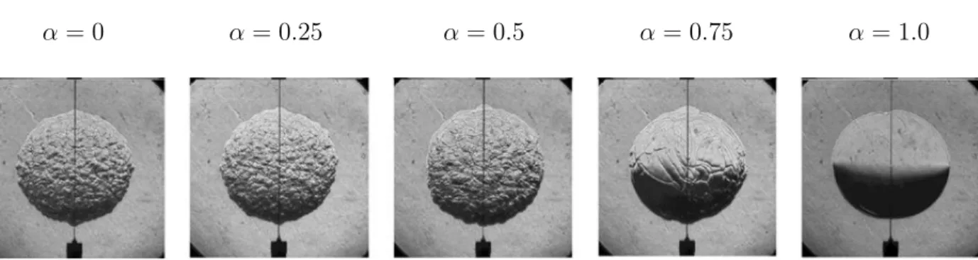
3.1 Spherical flames in air-propane-hydrogen mixtures; α corresponds to the mass
ratio of hydrogen in the fuel. Taken from [119] . . . 28
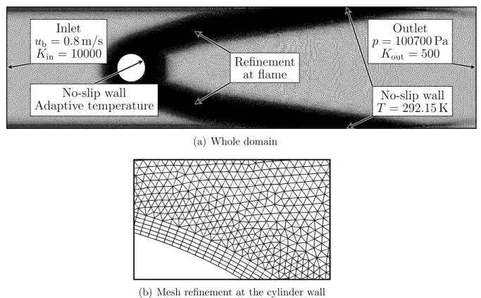
3.2 The INTRIG experiment; (a): Schematic; (b): Photograph of methane-air flame 29 3.3 2D-computational domain and mesh for the INTRIG configuration at a
cylin-der rotation rate of α = 0 (a) and inlay showing the refinement at the cylincylin-der
(b) . . . 31
3.4 Inlet velocity profile in simulation (line) versus experimental hot wire
mea-surements (red circles) . . . 31
LIST OF FIGURES
3.6 Steady state based on DNS; The field shows the flow speed in x-direction, the thin lines correspond to stream lines and the thick black line is the iso-surface of heat release. (a): α = 0; (b): α = 0.625; (c): α = 1.25; (d): α = 2.5; (e):
α = 3.75; (f): Definitions of the flame root positions, xroot,y±, tip positions,
xroot,y± and the bulk velocities in the respective upper and lower half planes,
vy± specified in Tab. 3.2 . . . 35
3.7 Sketch of a LTI system . . . 37
3.8 SI process in temporal domain via WHI and in frequency domain via harmonic
forcing . . . 39
3.9 Convertibility of IR and TF by the (inverse) z-transform . . . 39
3.10 Example of excitation signals for the acoustic forcing in the LDNS . . . 40
3.11 Comparison of flame topologies of the steady flame (black line) and instanta-neous snapshots of a pulsed flame (white iso surface of heat release) at various
phase angles of harmonic velocity perturbation (|u′| = 5%u
b, f = 100 Hz,
α = 0) . . . 41
3.12 (a) Flame normal displacements (see Fig. 3.12(b)) as a function of the flame position for a non rotating bluff body and various phase angles, φ, of harmonic
velocity perturbation of frequency f = 80 Hz and amplitude |u′| = 5%u
b; (b)
Schematics of laminar flame displacements; Thick solid line: unperturbed flame, thick dashed line: displaced flame; Definition of the flame angle, ϕ, flame displacement in flow direction, η, and flame normal displacement, ξ; u
indicates the fresh gas velocity and direction. . . 42
3.13 FTF based on WHI and harmonic forcing for a non rotating bluff body; K = 500 and 10000 curves correspond to the outlet relaxation coefficient in NSCBC
and lead to the same results. . . 43
3.14 IR based on WHI for a non rotating bluff body . . . 44
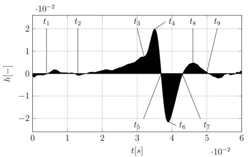
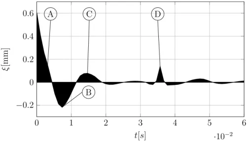
3.15 Flame root displacement, ξ0, caused by a Dirac like acoustic excitation (see
Eqn. (3.3.8)) in dependence of time . . . 45
3.16 Response of the flame topology to a short pulse of inlet velocity (see Eqn. (3.3.8)); Black line: Steady flame, white line: iso-surface of instantaneous heat release of the pulsed case; The times given are with respect to the end of the short
pulse. . . 46
3.17 Response to an acoustic pulse: Velocity fluctuations at the reference point for the determination of the FTF (upper axis) and heat release fluctuations
(lower axis) due to a dirac like acoustic pulse . . . 47
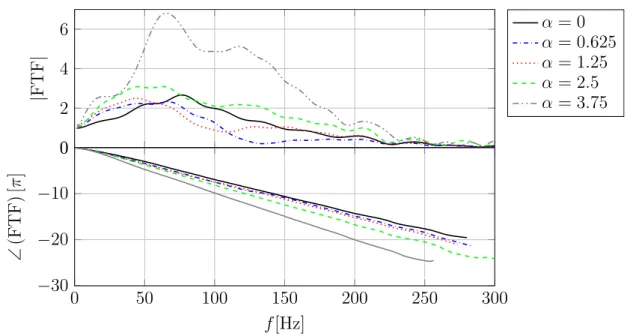
3.18 Global FTFs for various rotation rates based on WHI of DNS results . . . . 48
3.19 FTFs of the upper flame branch (y+) for various rotation rates based on WHI 49
3.20 FTFs of the lower flame branch (y−) for various rotation rates based on WHI 50
3.21 Comparisons of gains of global FTFs and of the single flame branches FTFs; Frequencies of ideal destructive and ideal constructive interference are marked
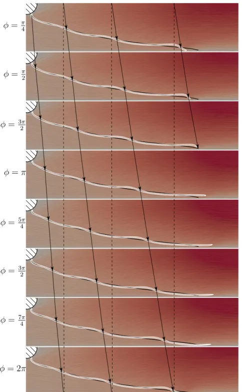
LIST OF FIGURES 3.22 Response of flame topology to acoustic forcing; flame normal displacement,
ξ, as a function of the flame front position, l for the upper and lower branch at various cylinder rotation rates and various phase angles of the harmonic
acoustic forcing of frequency 80 Hz and amplitude 5% ub . . . 54
3.23 Relative flame tip position with respect to the respective branches flame tip
postition of the steady flame, ∆x = xtip− xtip,st, versus the phase angle of
the velocity perturbation, φ; Cylinder rotation rate α = 0.625; pulsation
amplitude |u′| = 2%u
b; pulsation frequency fd,1 = 132 Hz . . . 54
4.1 Comparison of the concepts of DNS, LES and RANS . . . 60
4.2 Instantaneous snapshots of CFD simulations of a turbulent jet for DNS, LES
and RANS [145] . . . 61
4.3 DNS of a flame without artificial flame thickening (left) and with an artificial
thickening of F = 5 (right); taken from [190] . . . 64
5.1 Validation of the BiGlobal code: Radial and axial velocity component of the laminar base flow around a sphere at Re = 280.7; Azimuthal velocity
compo-nent is set to 0. . . 78
5.2 Validation of the BiGlobal code: Comparions of eigenfunctions with results
previously puplished in literature . . . 79
5.3 Schematic representation of a wave packet caused by a pulse introduced in
the flow at x = t = 0 for base flows with different stability properties . . . . 82
5.4 Example for temporal analysis: ωiand ωr as a function of the real axial wave
number for various azimuthal wave numbers in a non-swirling jet; taken from
Gallaire et Chomaz [74] . . . 83
5.5 Local stability analysis of an obstacle-free wake flow at a globally constant Reynolds number Re = 100, taken from Juniper et al. [105]; Streamlines,
and absolute frequency, ω0,i, α+i ( ) and α
−
i ( ) in dependence of streamwise
location; The spatial analysis leading to the α± branches in this case is based
on the frequency of a global LSA. . . 85
6.1 Azimuthal combustion chamber of a helicopter gas turbine; The chamber (see(a)) is fed by 15 two staged counter-rotative injectors, similar in geometry
to the one under investigation in this chapter (see (b) and (c)) . . . 92
6.2 Sketch of the cross section of the swirler . . . 93
6.3 Schematic set up of the preintrig experiment . . . 93
6.4 Experimental SPLs measured at x = 0 and r = 300 mm for the no-rod and
rod case . . . 94
6.5 Numerical domain and grid for the non-reactive simulations . . . 95
LIST OF FIGURES
6.7 Development of LES-pressure drop across the swirler with time during the successive mesh h-refinement (red thin line) in the no-rod case; Experimental
pressure drop (black thick line): ∆pexp = 3768 Pa; based on Daviller et al. [48] 97
6.8 Validation of LES mean flows in the Cartesian z = 0-plane in the free stream field versus the average of experimental PIV snapshots; LES fields are both
temporally and azimuthally averaged. . . 98
6.9 Fourier transform of numerical pressure measurements within the primary
injector for the no-rod and the rod case . . . 98
6.10 Mean fields of radial, azimuthal and axial velocity in the interior of the injector for the no-rod case (left) and the rod case (right); The LIC at the bottom are based on the mean radial and axial velocity component. . . 100 6.11 DMD spectra for the no-rod case and the rod case based on LES snapshots . 101 6.12 DMD-mode shapes in the y-z-plane at x = −3 mm (within the primary
injec-tor) based on three-dimensional LES snapshots for the no-rod PreINGTRIG case; single helix PVC in (a)-(d) corresponding to the dominant peak in Fig.6.11; double helix PVC in (e)-(h) corresponding to its first higher har-monic . . . 102 6.13 Phase averaged light intensity fluctuation of a flame perturbed by a PVC;
taken from [160] . . . 102 6.14 DMD mode shapes in the z-plane based on three-dimensional LES snapshots
of the two PreINTRIG configurations, the no-rod case (left) and the rod case (right); for corresponding DMD spectra, see 6.11; The illustrated mode shapes correspond to the maximum amplitude in the respective spectra. . . 103 6.15 Fields of molecular, LES subgrid, eddy and total viscosity for the PreINTRIG
configuration, averaged in time and azimuthal direction . . . 105 6.16 Base flow as used as input for the Linear Stability Analysis (LSA) obtained
by azimuthally averaging the velocity fields illustrated in Fig. 6.10 . . . 106 6.17 Example of local stability for two different axial positions in the swirler;
Ve-locity profile slighlty upstream (a) and slightly downstream (c) of the exit plane of the primary injector and their respective temporal stability maps (b) and (d) . . . 107 6.18 Estimation of the absolute frequency by localizing the saddle point of ω in the
complex α-plane . . . 108 6.19 Absolute frequency as a function of the streamwise position; the streamwise
coordinate is dedimensionalized by the distance between the dump plane and the center body; . . . 109 6.20 Estimation of the global frequency by localizing the saddle point of ω in the
complex α-plane . . . 110
6.21 α+ and α− branches as a function of the axial position; the swirler drafts in
LIST OF FIGURES 6.22 Mode shapes based on local stability analysis in a plane in the primary injector
(z = −3 mm) . . . 111 6.23 Reconstructed mode shapes based on local stability analysis in the r-z-plane 111 6.24 Numerical domain and grid for the BiGlobal LSA, exemplary for the no-rod
configuration . . . 112 6.25 BiGlobal spectrum of the no-rod case . . . 113 6.26 BiGlobal mode shapes of the no-rod configuration in the r-z-plane . . . 114 6.27 Adjoint BiGlobal mode shapes of the no-rod configuration in the r-z-plane . 114 6.28 Structural sensitivity of the no-rod configuration . . . 115 6.29 BiGlobal spectrum of the rod configuration . . . 116
6.30 BiGlobal Mode shapes of Branches 1, 2 and 3 (see Fig.6.29) in the r-z-plane 116
6.31 BiGLobal mode shapes of the rod configuration in the r-z-plane . . . 117 6.32 Pointcaré plots for the normalized pressure signal for both the no-rod (a) and
the rod case (b) for several time shifts, ∆t = t + nτ . . . 119 7.1 Numerical domain and grid for the reactive simulations . . . 124 7.2 Temporal mean of heat release rates indicating the flame shapes for the rod
and no-rod case for equivalence ratios of Φ = 0.75 and Φ = 1.0; ˙V = 3.4 ls−1 125
7.3 Temporal mean of heat release rates indicating the mean flame shapes for various flow rates in the rod and no-rod configuration; equivalence ratio Φ = 0.725 . . . 127 7.4 BiGlobal mean fields based on reactive Large Eddy Simulation (LES); Φ = 1.0;
˙
V = 1.7 ls−1 . . . 129
7.5 BiGlobal spectrum of the no-rod case for a reacting flow when the non-uniform
mean density field is neglected; Φ = 1.0; ˙V = 1.7 ls−1 . . . 130
7.6 BiGLobal mode shapes of the no-rod case in the r-z-plane for a reacting flow
when the non-uniform mean density field is neglected; Φ = 1.0; ˙V = 1.7 ls−1 . 131
7.7 BiGlobal spectrum of the no-rod case for a reacting flow when the non-uniform
mean density field is taken into account; Φ = 1.0; ˙V = 1.7 ls−1 . . . 132
7.8 BiGLobal mode shapes of the no-rod configuration in the r-z-plane for a reacting flow when the non-uniform mean density field is taken into account;
Φ = 1.0; ˙V = 1.7 ls−1 . . . 133
7.9 BiGlobal spectrum for the rod and the no-rod case for a reacting flow taking
List of Tables
3.1 Key parameters of the flow, including adiabatic flame temperature, Ta and
laminar flame speed sl . . . 32
3.2 Properties taken from the DNS solution for different rotation rates, α;
Defi-nitions of the listed quantities are provided in Fig. 3.6(f) . . . 34
3.3 Time delays of the two flame branches (τy+ and τy− for the upper and lower
branch, respectively) and values of the first two frequencies for destructive
interference (cf. Eq. (3.3.13)). . . 51
5.1 BCs for LSA in case of m = 1; n is the normal vector of the boundary. . . . 77
6.1 Comparison of nondimensional PVC frequencies and growth rates in the no-rod configuration based on the experiment, the LES and BiGlobal and local stability analysis; LES errors are with respect to the experiment, while LSA errors are based on the LES frequencies. Errors of growth rates are based on the frequency of the oscillation. . . 119 8.1 Comparison of computational time LES vs methods of LSA . . . 138
List of Symbols
Latin c Crosscorrelation vector c Group velocity c Speed of sound C Heat capacity d Number of dimensions D Diameter D Diffusion coefficient D Dissipatione Mass specific total energy E Total energy
f Body forces f Frequency F Flux tensor
F Flame thickening factor h Enthalpy h Height H Transfer function I Unity matrix k Species n Gain of FTFs
N Number of chemical species p Pressure
P Stem function for pressure perturbation
qHeat flux vector
q Heat release r Residual R Gas constant s Source term vector t Time
LIST OF SYMBOLS T Period
T Temperature u Velocity
U Stem function for velocity perturbation
v Noise signal in time domain V Diffusion velocity
V Noise signal in frequency domain V Volume
w Width
W Molecular mass
x First Cartesian coordinate x Input signal in time domain X Mole fraction
X Input signal in frequency domain y Output signal in time domain Y Mass fraction
y Second Cartesian coordinate
Y Output signal in frequency domain Z Number of Gauss-Lobatto points Z Complex stream wise coordinate z Third Cartesian coordinate Greek
α Rotation rate
α (Complex) wave number ǫ Emissiency coefficient Γ Autocorrelation matrix κ Adiabatic exponent λ Eigenvalue µ Dynamic viscosity ν Kinematic viscosity ω Chemical source term
ω (Complex) angular frequency Φ Vector of conserved variables Φ Equivalence ratio
Ψ Stem function for density perturbation ρ Density
σ Structural Sensitivity
τ Stress tensor
LIST OF SYMBOLS Dimensionless Quantities Cr Crest factor . . . Cr = … maxn(x2n) 1 N PN n=1x 2 n Ma Mach number . . . Ma = uc Pr Prandtl number . . . Pr = νa Re Reynolds number . . . Re = uD ν Sc Schmidt number . . . Sc = Dν Subscripts
0 Absolute (frequency/wave number) b Bulk speed c Constructive interference c Critical c Cut-off C Cell centered cond Conductive cyl Cylinder d Destructive interference e Eddy eff Effective in Inlet
LES LES sub-grid-scale m molecular out Outlet p Constant pressure rad Radiative reac Reactive ref Reference s Specific s Saddle Point s Sensible st Steady tip Flame tip v Constant volume
Abbreviations
AAVBP A Very Big Project B
BC Boundary Condition C
CFD Computational Fluid Dynamics CFL Courant-Friedrichs-Lewy
CI Combustion Instability CPU Central Processing Unit CRZ Central Recirculation Zone CV Cell Vertex
D
DMD Dynamic Mode Decomposition DNS Direct Numerical Simulation F
FEM Finite Element Method FFT Fast Fourier Transform FTF Flame Transfer Function G
GEVP Generalized Eigenvalue Problem I
ABBREVIATIONS IR Impulse Response L
LDNS Laminar Direct Numerical Simulation LES Large Eddy Simulation
LHS Left Hand Side
LIC Line Integral Convolution LSA Linear Stability Analysis LTI Linear Time Invariant LW Lax-Wendroff
N
NSCBC Navier-Stokes Characteristic Boundary Condition O
ORZ Outer Recirculation Zone P
P2G Power To Gas P2L Power To Liquid P2X Power To X
PIV Particle Image Velocimetry
POD Proper Orthogonal Decomposition PRBS Pseudo Random Binary Signal PVC Precessing Vortex Core
R
RANS Reynolds Averaged Navier-Stokes RHS Right Hand Side
S
SGS Sub-Grid-Scale SI System Identification SPL Sound Pressure Level T
TF Transfer Function
ABBREVIATIONS TTGC Two-Step Taylor-Galerkin C
U
UAV Unmanned Aerial Vehicle W
Chapter 1
Introduction
1.1
Combustion - A Future Technology?
“Most wholesome is the force of fire” wrote Friedrich Schiller, one of the most significant German classical writers, in his epochal poem The song of the bell in 1799. The excerpt (see Page iv of this manuscript) underlines the significance of combustion in this time. Its use, however, was restricted mainly to hand craft, like in the description in The song of the bell. Because then, when the industrial revolution was in full swing in Great Britain, the economy on the European continent and especially in Germany was still characterized by the agricultural sector [91]. The industrial revolution reached Germany late in the 1830s, around three decades after Schiller’s death. During the course of the industrial revolution, the exploitation of fossil fuels in combination with the flourishing art of engineering initiated a global technological, economical and social transition, the intensity and rapidity of which has never been witnessed before in human history. Without this boost and the use of carbon fuels down to the present day, today’s globalized world with its technologies, medicine and new industries would be inconceivable. Friedrich Schiller at his time and location, although referring to fire as a “heavenly force”, could not even grasp the actual potential of the use of combustion and its detrimental role in history that became apparent in retrospect only. Nevertheless, the limitations and downsides of fossil fuels are well known today. The first of which is the amount of fossil fuels available to exploit. Recent studies predict the depletion times of todays known reserves of oil and gas to be in 2040 and 2042, respectively, while
the coal reserves will last at least until the 22nd century [222]1. Of course depletion dates
like this were frequently delayed into the future due to exploration of new reserves and more
1The source was published before the method of hydraulic fracturing was applied on the large scale. The
CHAPTER 1. INTRODUCTION
efficient mining technologies. Nevertheless, the depletion of fossil fuels in general remains without doubt.
The second downside is with respect to the reaction products emerging from combustion processes. Probably the largest concern in this context is the impact of fossil fuel combustion on the global climate, a hypothesis which was firstly proclaimed by the end of the 19th century, amongst others by Arrhenius [7]. Today, the vast majority of scientists agree that
the CO2 emissions caused by the combustion of hydro carbons are the driving factor for an
increase in global temperatures, which have been observed during the last decades [174]. The result of further increasing global temperatures and therefore fossil fuel combustion could be increasing sea levels, harsher winters and more frequent floodings and droughts [108]. A recent study furthermore examines the possibility of self-reinforcing feedback mechanisms, e.g. the melting of permafrost in Siberia, which could cause additional significant increases in global temperatures [231].
Considering these downsides of fossil fuel combustion, the question arises whether the golden age of combustion is over, or if it will continue to shape the future in energy production. In order to address this question, it is helpful to analyze both the current energy markets and the alternatives to fossil fuels. Today’s available alternatives for electricity production is the use of renewable energies, mainly hydro, solar and wind power, and nuclear energy. The advantages of nuclear energy are the low energy costs and its marginal impact on
climate change, since it is almost CO2 neutral. Nevertheless, due to the unsolved question
of the disposal of burnt out fuel rods and several severe accidents in nuclear power plants, with catastrophic consequences, this technology is highly controversial. While some nations (or states), such as France, Turkey and Japan continue their efforts or start applying this technology, others, like Germany, California and Austria decided to either not develop or end their nuclear power programs. If they wish not to increase their share of fossil fuel consumption, renewable energies are their only option left. These countries which take on the challenge of transition to renewable energies face major problems. In the following, some of these problems will be discussed and also how combustion could help to solve them. To do so, the German energy market will serve as an example for a market in energy transition. Fig. 1.1 illustrates the share of energy sources in gross power generation in Germany, i.e. the total amount of produced electricity. Huge efforts have been taken on the political level in Germany in order to elevate the share of renewable energies during the last twenty years. Therefore, the German electricity is produced to one third by renewable energies, today, of which over three quarters are solar, wind and hydro electric energy. Together with nuclear
energy, almost half of the electricity production is CO2 neutral. While this seems like a huge
progress, a glance at Germany’s primary energy consumption (see Fig. 1.2) has a sobering effect. In contrast to the gross power generation the primary energy consumption includes traffic, which is mainly driven by fossil fuels, heating and combustion of primary energy carriers in industry. Here, the share of renewable energies is only at 13.1%, and within this
1.1. COMBUSTION - A FUTURE TECHNOLOGY? 4.3% Others 0.9% Mineral oil 13.2% Natural gas 33.3% Renewables 22.5% Lignite 14.1% Hard coal 22.5% Nuclear
Figure 1.1: Share of energy sources in gross power generation in Germany in 2017; Data based on [268] 1.8% Others 34.6% Mineral oil 23.7% Natural gas 13.1% Renewables 11.2% Lignite
11.0% Hard coal 6.1% Nuclear
Figure 1.2: Share of primary energy consumption in Germany in 2017; Data based on [267]
share almost two thirds are produced via combustion of biomass or waste. Elevating the renewable energies’ share over this threshold is difficult. This is due to the volatility of wind and solar energy. Fig. 1.3 illustrates the cumulative output powers over time of German wind and solar power plants. The volatility of both energy sources is evident. Besides fluctuations of a charactersitic time of hours, seasonal fluctuations are visible in the plots. While more solar power is produced in the summer months than in the winter months, it is opposite for wind power. Sinn [226], a renowned, yet controversial German economist, recently analyzed the available and potential buffering capabilities. He took into account the possibility of constructing new storage power plants and demand management, i.e. the artificial manipulation of demand in order to balance the momentary electric energy output with its consumption. He showed that high frequency fluctuations are comparably easy to buffer. The seasonal fluctuations in storage demand however, which are of much higher amplitude, pose the real challenge. He concludes that in case Germany wants to rely to 100% on solar and wind energy, approximately 40, 000 new hydroelectric storage power plants of average German size would have to be constructed, a number by far exceeding the Germany’s geographic potential for these kind of power plants. Furthermore, demand management, e.g. by smart power grids and consumption, has almost no effect on the seasonal fluctuations since it can only be applied to buffer high frequency fluctuations. But how can combustion help to
CHAPTER 1. INTRODUCTION
JulyAug.Sep.Oct.Nov.Dec.Jan.FebMar.A. pr.MayJune
0 10 20 Months 2017/2018 P [MW ] Mean: 6277 MW
(a) Windpower; Data based on [245]
JulyAug.Sep.Oct.Nov.Dec.Jan.FebMar.A. pr.MayJune
0 5 10 15 Months 2017/2018 P [MW ] Mean: 1588 MW
(b) Solarpower; Data based on [244]
Figure 1.3: Output of renewable energies in Germany in 2017/2018
solve this problem? The answer is called Power To X (P2X). The idea of these technologies is to store the excess energy which is provided by volatile renewable power plants in chemical form. In Power To Gas (P2G), electrical energy is used to produce combustible gases like hydrogen and methane, while in Power To Liquid (P2L), liquid fuels are produced. These technologies have increasingly been in the focus of research since the beginning of the 21st
century, due to the demand of storing electrical energy [204]. The CO2 needed in the P2G
production of methane and in the P2L production of liquid fuels can be captured in the exhaust of combustion power plants or directly from the air [263]. Once the electrical energy is transformed in chemical energy it can be stored even over large time spans [148]. This makes this technology attractive in order to buffer the seasonal fluctuations in the electricity balance. Especially the subsequent combustion in gas turbines has significant advantages: Firstly, gas turbines are highly flexible. Typical start-up times reach from 7 to 20 minutes. And secondly they can be used in a combined cycle with a steam turbine, where the excess heat can still be applied as district heat. This way, the energy in chemical form can not only be transformed in electrical energy, but it can also be used for heating, which today is still mainly covered by fossil fuels. This way P2X provides the potential to increase the share of renewable energies in electricity consumption, but also in heating.
Finally, the P2L technology can be used to tackle the last big sector in primary energy consumption: traffic. Producers of electric cars today struggle with the expensive, heavy and environmentally questionable batteries, which are needed in order to store the electric energy. Especially commercial aviation is highly dependent on fossil fuels today. While the market for Unmanned Aerial Vehicles (UAVs), the so called drones, is booming [31], alternatives to liquid fuels are not in sight in the frame work of large scale passenger and
1.1. COMBUSTION - A FUTURE TECHNOLOGY? cargo transport. At the same time predictions for both cargo and passenger flights are expected to explode during the next decades [101, 69, 2], which will lead to a higher demand in combustible fuels in this sector, which partially could be provided by P2L.
1993199419951996199719981999200020012002200320042005200620072008200920102011201220132014201520162017 0 2 4 6 8 10 12 14 Year B il li on to n n es oi l eq u iv al en t Coal Renewable Nuclear Natural gas Minearal oil
Figure 1.4: Development of global primary energy consumption since 1992; Data based on [20]
The P2X technologies may at some point be an important tool in the framework of renewable energy transition. Nevertheless, on the global level we still are far from this point. In general, the significance of combustion in the present and also the near future’s forecast of energy production is extraordinary. Figure 1.4 shows the development of global primary energy sources during the last 25 years. Without doubt, the share of renewable energy sources has increased. Nevertheless, the recent increase in fossil fuel consumption exceeds the increase in renewable energy many times over, so that today the share of combustion in global energy transition is close to 90% [213, 156]. In line with sustainability and climate protection it is therefore mandatory that fossil fuels are burnt with highest possible efficiency, since they are the predominant energy carrier of the present and will remain so for many years to come [117].
To conclude, combustion did not only allow for the industrial revolution by the consumption of fossil fuels during the preceding centuries, it also is by far the dominant energy source of the present. Furthermore, the use of power to gas it is a promising tool to shape the future of energy production in the framework of transition to renewable energies. It therefore is the task of both research and industry to continue their effort in developing combustion
CHAPTER 1. INTRODUCTION
Figure 1.5: Destructive impact of CIs; Burner nozzle before (left) and after (right) a CI event
engines of increasingly high efficiency in order to both limit the impact of combustion on our environment and to support energy transition to renewable resources.
1.2
Fundamentals of Thermoacoustics
As laid out in the previous chapter one strength of gas turbines is their high flexibility and short start-up time. One factor that can limit this flexibility and prevent stationary gas turbines (but also aeronautical gas turbines and rocket engines) from running at their optimal operating point can be the onset of Combustion Instabilitys (CIs). If not taken care of, these instabilities can cause serious damage to the structural integrity of the combustion chamber. Fig. 1.5 shows the destructive capabilities of CIs. Unfortunately, lean combustion regimes,
which are favored due to lower flame temperatures and therefore lower NOx emissions [24],
are especially vulnerable to these kind of instabilities [52, 28]. Being able to control CIs therefore may reduce nitric oxide emissions and enhance the efficiency of gas turbines.
1.2.1
On the Cause and Nature of Thermoacoustic Instabilities
One source of a fluctuation in heat release in a flame is turbulence. As turbulence typically consists of broad band frequencies, the flame’s response to turbulence is typically broad band and incoherent [26]. These heat release fluctuations in the flame in turn emit sound waves, which are known as combustion noise [58]. While this is typically not a problem concerning safety or efficiency, several recent studies focus on this phenomenon in order to understand combustion noise and thereby reduce unwanted structural vibrations and noise emission of aerospace engines [155, 230, 235, 27].
1.2. FUNDAMENTALS OF THERMOACOUSTICS Acoustic oscillation Heat release oscillation Flow and mixture perturbation amplifies causes causes
Figure 1.6: Feedback loop leeding to a thermoacoustic instability in a combustion engine; based on [133]
In certain cases however, the heat release fluctuation locks in an acoustic mode of the combus-tion chamber. This phenomenon is based on the thermoacoustic effect, i.e. a feedback loop between an acoustic mode of the chamber and the heat release fluctuation in the flame. A schematic representation of an thermoacoustic instability is illustrated in Fig. 1.6. The ther-moacoustic effect was discribed first by Lord Rayleigh at the end of the 20th century [200]. He stated that in order for a thermoacoustic instability to arise, a pressure fluctuation based
on an acoustic mode of a vessel, p′, must be in phase with the heat release fluctuation caused
by the same acoustic mode, q′. This is known as the famous Rayleigh criterion:
Z T 0 Z V 0 p ′(x, t)q′(x, t)dv dt >Z T 0 Z V 0 D(x, t)dv dt, (1.2.1)
where t and T stand for the time and the period of an oscillation, respectively, and V and v for the volume. x is the spatial coordinate, while D stands for the wave energy dissipation. The equation above states, that if the pressure acoustic energy source term on the Left Hand Side (LHS) is greater than the dampening (e.g. by acoustic dampening at walls or partially acoustically open inlets and outlets) then a thermoacoustic instability arises. A typical pressure fluctuation trace of the onset of a thermoacoustic instability is illustrated in Fig. 1.7. A small fluctuation, e.g. caused by turbulence, is sufficient to trigger an acoustic mode. In the linear regime, i.e. where non-linear effects are negligible, the amplitude of pressure fluctuation increases exponentially (t < 50 in Fig 1.7). When non-linear effects become large, the growth in amplitude decreases until a steady limit cycle is reached. In many cases an overshoot between the linear growth and the steady limit cycle is observed as can be seen in Fig. 1.7.
The mechanisms that cause flame fluctuations due to acoustic waves are manifold. They depend both on the combustor type and fuel. Firstly, and most evidently, acoustic waves cause a fluctuation of fresh gas flow rate into the combustion chamber. This leads to a variation of flame surface, which is directly linked to the heat release rate. This mechanism
CHAPTER 1. INTRODUCTION 0 20 40 60 80 100 120 140 −1 0 1 t p ′ Linear regime exponential growth
Overshoot Stable limit cycle
Figure 1.7: Typical pressure trace of the transient to a thermoacoustic oscillation to its limit cycle; based on [133]
was studied in various studies, involving premixed swirled [121, 252] and bunsen flames [217], as well as bluff body stabilized flames [144, 201].
A quite related mechanism is the creation of equivalence ratio fluctuations, based on a different receptivity to acoustics of the fuel and the oxidizer line in partially premixed or non-premixed flames. This mechanism was for example studied for swirled flames [236, 122] and theoretically for Bunsen burners [132].
Another mechanism is the cause of vortex shedding based on the Kelvin-Helmholz insta-bility [32]. As the vortex reaches the flame, this in turn can lead to an increase in flame surface and therefore to heat release fluctuations. This effect was observed amongst others in studies involving bluff body stabilized flames [201, 203, 191] for flames in the wake of a backward facing step [269] and in ramjet exmerimental engines [25]. A review over flame vortex interactions is given by Candel [29]. More recently, Oberleithner et al.[172] showed a direct connection between the shear layer receptivity and the flames response to acoustic forcing.
In the case of liquid fuels the interaction between the liquid phase and the gaseous phase can lead to several mechanisms leading to CIs [44]. Davvur et al. [63] describe the impact of acoustic waves on the droplet evaporation process and show that this interaction can lead to CIs. The slip velocity, i.e. the velocity difference between the fluid phase and the gaseous phase due to their different inertia, was proven to cause thermoacoustic oscillations in some cases [51].
The examples above, that only pose an overview over the various different mechanisms lead-ing to CIs, demonstrate how diverse the causes for thermoacoustic oscillations are. Keeplead-ing in mind the complexity of the phenomena leading to these instabilities, it is not surprising,
1.2. FUNDAMENTALS OF THERMOACOUSTICS that their prediction is difficult and they most often become apparent in the last stages of the development process of a gas turbine or rocket engine [188]. Finding out that the newly developed engine is prone to high amplitude CIs is the worst case scenario for a development team and can make comprehensive changes to the engine design necessary. This in turn can be costly. A well known example for this is the development of the F-1 engine, the first-stage rocket engine that landed men on the moon during the Apollo mission [173]. In order to get the thermoacoustic instabilities under control, 108 different injector plates were tested in 1332 full scale experiments until a sufficiently stable configuration was found[6]. It is supposed to be the most expensive project solely focusing on thermoacoustics in history [45].
1.2.2
Analysis Tools for Thermoacoustic Instabilities in
Combus-tion Systems
In the last decades the prediction tools have developed significantly in comparison with the development of the F-1 engine. Nevertheless, the prediction of combustion instabilities remains a difficult topic. Besides an exhaustive number of experimental investigations on the topic, several new analytic and numeric tools enhanced the knowledge of combustion systems in general and their stability behavior. In the following two categories of the latter will be described.
1.2.2.1 Brute-Force Time Integration of the Full Set of Reactive Navier-Stokes
Equations
Of course, knowing the behavior of a flame in a combustion chamber already at early stages of the development process by the aid of Computational Fluid Dynamics (CFD) is the dream of every gas turbine engineer. Direct Numerical Simulation (DNS), i.e. CFD simulations resolving the Kolmogorov scale and therefore the whole turbulence spectrum, would make this possible. Due to the large difference in orders of magnitude between the length scales of the combustor and the Kolmogorov scale this however is not affordable for the moment [190]. However it might become possible in the not too distant future [147, 163]. Reynolds Av-eraged Navier-Stokes (RANS), i. e. solving the Navier-Stokes equations for the temporal mean values by modelling the fluctuating quantities on the other hand is known not to ac-count for unstable behavior of the flow. A widely applied trade off between precision and affordability are LES [87, 253]. In this approach, small scale turbulence is modeled while large scale turbulence is resolved by the simulation. Besides the smallest turbulence length scale, which limits this approach, there are several aspects that still make this approach a challenge. It is a multiphysics problem, as it includes among others chemistry [76], turbu-lence flame interaction [254, 194], particle flows [219], evaporation processes [94, 1], solid structure interaction [115], correct modeling of acoustic boundary conditions [189, 55] and
CHAPTER 1. INTRODUCTION
the list goes on and on. Nevertheless, due to advancement in the last decades in the topic and a reduction of Central Processing Unit (CPU)-hour costs, today this approach is not only widely applied in research, but also increasingly for industrial purposes.
1.2.2.2 Isolation of Physical Phenomena by Low(er) Order Approaches
In many cases it can be advantageous to isolate certain physical phenomena in a combustion system instead of following the brute-force approach described in the preceding section. This can provide additional information about this phenomenon, which may be difficult to extract from the brute-force approach. Another reason is, that these approaches are typically cheaper and only take a fractional ammount of CPU-hours in comparison with the brute-force approach. A common approach in the framework of thermoacoustics is the analysis of the Helmholtz equation, which is based on a small perturbation approach and describes the acoustics in a vessel assuming that the flow velocity is equal to 0. It reads:
γp0∇ · Ç 1 ρ0 ∇Ùp å + ω2Ùp = iω (γ − 1)q(x).Û (1.2.2)
Here, the variables γ, p0, Ùp, ρ0, ω and q are the isentropic exponent, the mean pressure,Û
the pressure fluctuation, the mean density, the circular frequency of the acoustic mode and the fluctuation of heat release, respectively. For non-reacting flows the Right Hand Side
(RHS) is equal to zero and the equation poses a linear eigenvalue problem for ω2. Solving
the equation over the volume of a vessel with suitable boundary conditions applied yields the eigenvectors describing the pressure mode shapes and the corresponding eigenvalues describe the respective frequencies. In order to evaluate the stability behavior of a combustion system, the interaction of the pressure fluctuations of the mode and the heat release in the flame must be taken in to account, which is described by the term on the RHS of the Helmholtz equation. In this case the Helmholtz equation becomes a non-linear eigenvalue problem for the circular frequency, ω. Yet, the equation remains to be closed by describing the flame’s response in terms of heat release to the pressure fluctuation. This link is provided by the Flame Transfer Function (FTF), which relates the heat release signal to the acoustic velocity
at a reference point, xref. In Crocco’s n-τ-model [41, 42] it is described by
Û
q (x) = n (x)u (xe ref) exp (iωτ ) . (1.2.3)
A FTF can be based on analytical desciriptions [57, 60, 131, 218] and experimental [114, 60, 177, 214] or numerical measurements [109, 78, 35]. Once the FTF is known to sufficient accuracy, the influence of geometry adaptations or boundary conditions on the stability properties of the combustion system can be examined by solving Eqn. (1.2.3).
Further, the application of network models is a promising way to perform parameter studies on thermoacoustics (see e.g. Bellucci et al. [16] and Schuermanns et al. [216]). In this
1.3. IMPACT OF FLOW ROTATION ON FLAME DYNAMICS approach, a combustion system is divided in sub-systems, each of which is described by a scattering function for the one dimensional upstream and downstream traveling acoustic waves. The dynamics of the system are described by combining the sub-systems scattering functions. This approach is an exceptionally CPU-time saving way to investigate CIs. Another phenomenon that occurs in various fields of fluid dynamics and does so as well in combustion systems is the evolution of coherent hydrodynamic structures in free or boundary shear layers. The examples reach from a flame anchoring in the wake of a backward facing step [5, 186] to a bluff body stabilized flame [79, 223]. As mentioned above, they were in many cases shown to interfere with or lead to combustion instabilities [32, 201, 203, 191, 269, 25, 29]. A way to isolate this phenomenon is the LSA. Like the Helmholtz equation, the LSA is based on a small perturbation approach, where the velocities and the pressure are linearized in the Navier-Stokes equations. This method was applied in various fields of fluid dynamics. Amongst those are canonical flows, like the Poiseuille flow and the Couette flow [169], and plasma physics [159]. In recent years, this approach was also applied to study the Precessing Vortex Core (PVC) in the flow field of fuel injection systems. In the following section, this effect will be examined in greater detail.
1.3
Impact of Flow Rotation on Flame Dynamics
The interference of flow rotation, i.e. vortices, and flames is a frequently studied topic. Especially in the context of sub grid scale models in LES and RANS the turbulence flame interaction is of interest. Turbulence in cold flows is already a highly complicated phe-nomenon, which up to today is not well understood. The coupling of turbulence and flame is two-ways, meaning that vortices can have an impact on the chemistry, while flame can also impact turbulence [190]. In some cases a flame can increase the turbulence level [164], while in others it may laminarize the flow [127]. The strongest effect of turbulence on flames is the wrinkling of the flame, first described by Damköhler [47]. Due to this effect the consumption rate increases, which leads on the large scale to an increase in flame speed, which then is called turbulent flame speed.
The origin of turbulence are large scale instabilities, which often manifest as vortices in shear layers. Then the kinetic energy of these large scale instabilities is dissipated down the turbulent energy cascade. But not only the small scale turbulence impacts the flame dynamics, also the large scale hydrodynamic instabilities may have a significant impact on the consumption rate, if they interact with a flame [32, 201, 203, 191].
In fuel injection systems of gas turbines, large scale flow rotation may even occur manifold. Most modern injection systems are swirled, which means the fresh gas is injected in a jet with a strong azimuthal velocity component, and therefore rotation. For sufficiently large
CHAPTER 1. INTRODUCTION
Figure 1.8: PVC in a swirling jet; taken from [183]
swirl, a phenomenon called vortex breakdown, i.e. the evolution of a Central Recirculation Zone (CRZ) at the jet axis, occurs. This provides flame anchoring in the CRZ. Furthermore, swirl is thought of increasing turbulence levels and therefore the turbulent flame speed. Another flow rotation, which enhances this effect is the evolution of a coherent structure in the shear layer between the CRZ and the surrounding jet: The PVC (see Fig. 1.8). This phenomenon is furthermore thought of enhancing fuel atomization and mixing [233]. In recent years, this phenomenon has been more and more in the focus of research due to its beneficial contribution to combustion, but also due to its coherent nature, which might lock in a thermoacoustic instability [160, 80].
Another case where large scale flow rotation has an impact on combustion is the case of a laminar flame stabilized in the wake of a cylindrical flame holder. In case the cylinder is not moving, two symmetric flame branches occur, one at each side of the cylinder [158]. However, turning the cylinder around its axis it creates flow rotation. This flow rotation in turn causes a symmetry break between both steady flame branches [262, 152] (see Fig. 1.9). While the impact of the flow rotation on the steady flame branches was examined in previous studies by Mejia et al. [152] and Xavier et al. [262], its impact on the flame dynamics remains unknown.
1.4. OBJECTIVES Experiments DNS 1 2 3 4
Figure 1.9: Flame shape of a laminar flame anchored in the wake of a cylindrical bluff body for various rotation rates of the cylinder based on experiments and DNS; non-rotating cylinder at the left top; rotation rate increases from frame 1 to 4; taken from [152]
1.4
Objectives
The goal of this thesis is to investigate the origin and the effect of large scale flow rotation on flames. In this context two configurations are considered.
Part I studies the first case. Here, the flow rotation introduced by a rotating cylindrical flame holder in laminar cross flow (see Fig. 1.9) is investigated. Introducing flow rotation by turning the flame holder in this context is an elegant way to change the flame shape, without changing the geometry of the combustion chamber or the operating point. Based on the different shape of both flame branches, it can be assumed that their dynamics may be different as well. The goal of the first part of the thesis is to test this hypothesis. To do so, DNS are applied and the response of the flames to acoustic forcing is investigated. The second part of the thesis focuses on the other large scale flow rotation phenomenon introduced in the last section. Namely, the evolution of hydrodynamic instabilities in shear layers, or more specifically the PVC. This phenomenon has been increasingly investigated in the last years. Several studies identified the phenomenon as a global mode [75, 130, 209], that appears after a supercritical Hopf bifurcation. The parameter the change of which leads to the bifurcation can be the Reynolds number [209] or the swirl number [130]. The PVC was investigated by experimental and numerical means (e.g. [206, 165]). In various studies LSA was applied to understand the origin of the PVC. Mostly simple academic swirlers
CHAPTER 1. INTRODUCTION
were analyzed by local stability analysis, which is restricted to parallel or weakly-nonparallel jets. Global stability analyses, which are not restricted by a parallel flow assumption, were applied, however most solvers use structured meshes. Most real, modern combustion systems however are of highly complex geometry. Therefore, neither the parallel flow assumption is well met, nor structured meshes can be applied.
So far, LSA was applied mainly to understand the PVC in the context of academical config-urations. The goal of the second part of this thesis is to take the first step towards industrial applications, by extending the applicability to complex geometries and develop analysis tools for the control of the PVC. First, local stability analysis is reviewed and a global LSA strat-egy based on an unstructured mesh is presented. The applicability of both approaches on an industrial swirled fuel injection system is investigated, and their results will be applied to find information where the PVC is most receptive to external forcing, and therefore control. Furthermore, geometry changes in the injector and their impact on the PVC remain an open question, which could be answered by LSA. In this context, the influence of a central plug in the primary injector on the PVC will be analyzed in both non-reactive and reactive flows by LES and LSA. Finally, the impact of the density change across the flame front remains not addressed by the global LSA approach and will be investigated in this thesis.
1.4. OBJECTIVES
Part I: Symmetry break-ing by flow rotation
Part II: Flow rotation in fuel injection systems
Ob jectiv es Exp erimen tal Setup Numerical Setup
Analyze flame dynamics of a laminar flame stabilized on a rotating cylinder with respect to
• Flame topology
• Flame Transfer Function
Analyze
• the origin of hydrodynamic instabilities in complex (industrial) geometries
• the influence of a central plug in a fuel in-jection system on the hydrodynamic stbility in both non-reacting and reacting cnofigura-tions
• the effect of a flame on hydrodynamic stabil-ity
The INTRIG experiment of the INTECOCIS project at IMFT (Conducted by Daniel Mejia and Pradip Xavier)
Static cylinder
Rotating cylinder
PreINTRIG setup at IMFT, cold flow through a two-staged industrial swirled injection system (Conducted by Pradip Xavier): PIV and micro-phone measurements; no experiments performed for reacting flows
2-D Laminar Direct Numerical Simulations (the experiment is quasi 2-D) performed with AVBP with detailed chemistry (19 transported species)
• Large Eddy Simulation performed with AVBP; Thickened Flame model and two-step chemistry (BFER)
• Hydrodynamic Linear Stability Analysis: Local approach: Chebychev collocation; Global Approach: Finite-Element method
Ûur Ûuθ Ûuz Ûp
LES/DMD
lo
c.
Part I
Symmetry Breaking by Flow Rotation:
Impact on the Thermoacoustic
Chapter 2
DNS Tools
In every CFD project a trade off has to be made between required accuracy and the avail-ability of computational resources. One of the determining questions in this context is which method for the solution of the Navier-Stokes equations is applied. These methods can be categorized into three groups. In the first two groups - RANS and LES - the computational grid is not sufficiently refined in order to resolve the smallest turbulent length scales, which are attributed to the Kolmogorov scale. In fact, in the case of RANS the equations are solved for the mean flow, meaning no temporal fluctuations of the resolved conservative variables occur. For these two groups of methods, the Reynolds stresses caused by the sub grid velocity fluctuations therefore are a priori unknown and must be provided by an appropriate model, which in general yield a turbulent contribution to diffusion and viscosity. RANS heretofore has been both applied in industry and research due to its unbeatable numerical costs. Its drawbacks on the other hand are that temporal flow fluctuations are not considered and that the approach is often imprecise. In LES on the other hand large eddies are resolved while small eddies are to be modeled. While in the past LES used to be mainly restricted to academical studies, today this approach is increasingly applied for industrial purposes. A more detailed description of the approach will be given in Chapter 4. In contrast to the latter methods, in the third group, the DNS, the numerical mesh is sufficiently refined to account for the smallest fluctuation length scales. The Reynolds stresses which act on the mean field quantities are directly solved for and no models for additional viscosity or diffusion have to be considered. If conducted properly, DNS is a highly reliant tool. Nevertheless, due to its high computational costs applications remain mainly restricted to academic applications today.
In the framework of numerical simulation of laminar flames DNS is a widely used method. It nevertheless is more appropriate to use the phrase Laminar Direct Numerical Simulation (LDNS) in this context, since the Kolmogorov length scale is not resolved due to the absence of turbulence. The maximum length scale for the computational grid therefore is most
![Figure 1.2: Share of primary energy consumption in Germany in 2017; Data based on [267]](https://thumb-eu.123doks.com/thumbv2/123doknet/2961104.81451/37.892.119.800.423.574/figure-share-primary-energy-consumption-germany-data-based.webp)

![Figure 1.7: Typical pressure trace of the transient to a thermoacoustic oscillation to its limit cycle; based on [133]](https://thumb-eu.123doks.com/thumbv2/123doknet/2961104.81451/42.892.108.735.156.395/figure-typical-pressure-trace-transient-thermoacoustic-oscillation-limit.webp)