EUROSTEEL 2011, August 31 - September 2, 2011, Budapest, Hungary
CONNECTIONS WITH FOUR BOLTS PER HORIZONTAL ROW
Application of Eurocode 3Jean-François Demonceau a, Jean-Pierre Jaspart a, Klaus Weynand b, Ralf Oerder b and Christian Müller b
a
Liège University, Dept. Argenco, Belgium b
Feldmann + Weynand GmbH, Aachen, Germany
INTRODUCTION
Eurocode 3 Part 1-8 provides detailed application rules for the design of bolted end-plate connections. Although these rules apply to connections with any number of vertical bolt rows, most of them are limited to configurations with two bolts only in each horizontal row, i.e. one bolt on each side of the beam or column web. However, it is sometimes more economic to place four bolts in one row, for instance when wide flange H-sections are used. This configuration is commonly met in different countries in Europe and, in particular, in Germany where this configuration is even standardized. The theoretical model on which the Eurocode 3 application rules are founded is general and can be potentially applied to connections with four bolts per horizontal row. However, specific design rules are not given in Eurocode 3 and need to be developed. Within the present article, easy-to-apply analytical design rules aimed at predicting the mechanical properties of connections with four bolts per row, being in full agreement with the Eurocode 3 approach, are presented. In particular, comparisons to less recent analytical procedures are given.
1 GENERALITIES
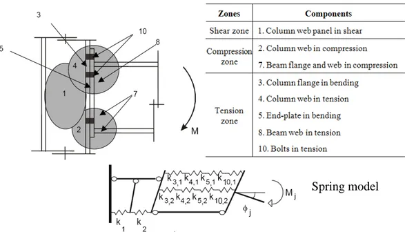
The analytical model recommended in the Eurocodes to characterise the mechanical properties of a joint is founded on the “component method” which is, nowadays, a widely recognised procedure for the evaluation of the design properties of structural joints. This method applies to any type of steel or composite joints, whatever the geometrical configuration, the type of loading (axial force and/or bending moment, ...) and the type of member sections. This method considers any joint as a set of individual basic components. For the particular joint shown in Fig. 1 (steel joint configuration with an extended end-plate connection subjected to hogging bending moments), the relevant components are given.
Each of these basic components possesses its own strength and stiffness either in tension, in compression or in shear (spring model – see Fig. 1). The column web is subjected to coincident compression, tension and shear. The coexistence of several components within the same joint element can obviously lead to stress interactions that are likely to decrease the resistance of the individual basic components; such interactions are taken into account within the method.
The application of the component method requires the following steps: (i) identification of the active components in the joint being considered, (ii) evaluation of the stiffness and/or resistance characteristics for each individual basic component and (iii) assembly of all the constituent components and evaluation of the stiffness and/or resistance characteristics of the whole joint (specific characteristics - initial stiffness Sj,ini, design resistance Mj,Rd, ... - or the whole moment-rotation curve).
In Eurocode 3[1], an analytical assembly procedure is described for the evaluation of the initial stiffness Sj,ini and the design moment resistance Mj,Rd of steel joints. The application of the component method requires a sufficient knowledge of the behaviour of the basic components; as previously mentioned most of the proposed design rules in the Eurocodes only cover joints with two bolts per row.
The components which are the most affected by the presence of four bolts instead of two are the components in bending, i.e. the “column flange in bending” and the “end-plate in bending”. In the
Fig. 1. Steel joint with an extended end-plate connection subjected to hogging moments
2 COMPONENTS IN BENDING WITH FOUR BOLTS PER ROW
2.1 T-stub model
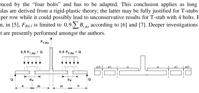
The design rules for these components, as suggested in the Eurocodes, are founded on the “T-stub approach”, firstly introduced by Zoetemeijer [2]. This approach consists in substituting the tensile part of the connection by T-stub sections of appropriate effective length leff, connected by their flange onto a presumably infinitely rigid foundation and subjected to a uniformly distributed force acting in the web plate (Fig. 2).
Fig. 2. T-stub idealization and possible failure modes
Through this approach, three different failure modes may be identified (Fig. 2): onset of a yield lines mechanism in the plate before the strength of the bolts is exhausted (Mode 1), bolt fracture without prying forces, as a result of a very large stiffness of the plate (Mode 3) and mixed failure involving yield lines – but not a full plastic mechanism – in the plate and exhaustion of the bolt strength (Mode 2).
Within the Eurocodes, formulas to predict the design resistance of a T-stub flange with two bolts per row are given for each failure mode; the latter have been extended to T-stub configurations with four bolts per row (see Fig. 3) in [3] and are reported in Table 1. Within this table, it can be observed that the formulas for Mode 1 and 3 remain unchanged; only the one related to Mode 2 is
Mode 1 Mode 2 Mode 3 F Column web or beam web End-plate or column flange Spring model
influenced by the “four bolts” and has to be adapted. This conclusion applies as long as the formulas are derived from a rigid-plastic theory; the latter may be fully justified for T-stubs with 2 bolts per row while it could possibly lead to unconservative results for T-stub with 4 bolts. For this reason, in [5], FRd,3 is limited to 0, 9.
∑
Bt Rd, according to [6] and [7]. Deeper investigations of thisaspect are presently performed amongst the authors.
Fig. 3. Definitions of the parameters for T-stubs with two or four bolts
Table 1. Formulas to predict the design resistance of T-stubs for each possible failure mode
Failure modes T-stub with 2 bolts T-stub with 4 bolts
Mode 1 ,1, ,1 (8 2 ) 2 ( ) − = − + w pl Rd Rd w n e M F mn e m n ,1, ,1 (8 2 ) 2 ( ) − = − + w pl Rd Rd w n e M F mn e m n Mode 2 ,2, , ,2 2 + = +
∑
pl Rd t Rd Rd M n B F m n ,2=min( ,2, ; ,2, ) with Rd Rd p Rd np F F F 2 2 , 1 2 1 2 ,2, 1 2 ,2, 1 2 2 2 2 .( ) 2 ( ) + + + + = + +∑
t Rd pl Rd Rd p B n n n n M n n F m n n , ,1, 1 ,2, 1 2 . 2 ( ) + = +∑
t Rd pl Rd Rd np B M n F m n Mode 3 FRd,3 =∑
Bt Rd, ,3 , ,(but limited in practice to 0,9 ([6] & [7])
=
∑
∑
Rd t Rd t Rd F B B With:• m defined in [1] (see Fig. 3);
• ew = dw/4 (see Fig. 3);
•
Σ
Bt,Rd sum of the design resistances of the bolts connecting the T-stub to the rigid foundation;• 2
,1, =0, 25 ,1 / 0
pl Rd eff f y M
M l t f γ andMpl,2,Rd =0, 25leff,2t f2f y/γM0;
• tf the thickness of the T-stub flange and fy the yield strength of the T-stub steel;
• leff,1 minimum effective length associated to circular or non-circular patterns (see next section); • leff,2 minimum effective length associated to non-circular patterns (see next section)
• For T-stub with 2 bolts, n is defined in Fig. 3 with n ≤ 1,25m;
• For T-stub with 4 bolts, n = e1 + e2 (Fig. 3) with n ≤ 1,25m, n1 = e1 and n2 = e2 with n2 ≤ 1,25m+n1.
For the T-stub approach, the definition of accurate effective lengths is required; the values of the latter are mainly linked to the plastic mechanisms (made of plastic yield lines) which could develop within the considered component. Tables with analytical formulas to compute the latter are proposed in Eurocode 3 for an end-plate or a column flange with two bolts per row [1]. For the joint configuration with four bolts per row, the definition of such effective lengths was not available; it is the subject of the following section.
2.2 Computation of the effective lengths for components in bending with four bolts per row
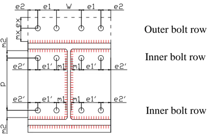
The presence of four bolts per row instead of two influences the development of the plastic yield lines within the components in bending. In Table 2, a summary of the analytical formulas to predict these effective lengths is given for outer bolt rows and inner bolt rows met in standardised “German” joint configurations (see Fig. 4), both for circular and non-circular yield patterns as defined in Eurocode 3 [1]; these formulas are based on the ones defined in [4] for joints with two bolts per row. The parameters which are used in the formulas presented here below are defined in
Fig. 4; the computation of mx, m1, m2 and α has to be performed in agreement with the Eurocode
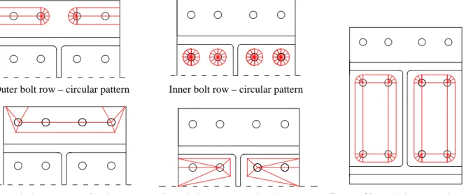
recommendation [1]. Some examples of possible yield patterns for the considered bolt rows are illustrated in Fig. 5; all the possible yield patterns are described in detail in [3].
It is important to notice that a fundamental difference exists in the definition of the equivalent T-stub for the outer and inner bolt rows. For an outer bolt row, the T-T-stub to be considered is a T-T-stub with two bolts (the T-stub web is the beam flange); the presence of four bolts within this row only influences the values of the effective lengths. For an inner bolt row, the T-stub to be considered is a T-stub with four bolts (the T-stub web is the beam web).
Fig. 4. Definition of the parameters used in the computation of the effective lengths
Table 2. Analytical formulas to predict the effective lengths for outer and inner bolt rows
Circular patterns Non-circular patterns
Outer bolt row
, =min , ; , ; , ; ,
eff c eff I eff II eff III eff IV
l l l l l leff nc, =minleff V, ;leff VI, ;leff VII, ;leff VIII, ;leff IX, , =4 eff I x l πm leff V, =2mx+0, 625ex+(e1+e2) , = + +2 1 eff II x l πm w e leff VI, =4mx+1, 25ex+e1 , =2( + 1) eff III x l πm e leff VII, =2mx+0, 625ex+ +e1 0, 5w , = +2(1+ 2) eff IV x l πm e e leff VIII, =0,5(2e1+2e2+w) , =8 +2, 5 eff IX x x l m e
Inner bolt row leff c, =leff X, =4πm1 leff nc, =leff XI, =αm1
Inner bolt row as part of a group
, =min , ; ,
eff c eff XII eff XIII
l l l leff nc, =leff XIV, , = 1+ + 1' eff XII l πm p e , =2( 1+ ) eff XIII l πm p leff XIV, =αm1+0, 5p−(2m1+0, 625( 'e1 +e2'))
Outer bolt row Inner bolt row
Outer bolt row – circular pattern Inner bolt row – circular pattern
Outer bolt row – non-circular pattern Inner bolt row – non-circular pattern Group of inner bolt rows – circ. pattern
Fig. 5. Examples of possible plastic yield patterns for outer and inner bolt rows with four bolts per
row
With the so-defined effective lengths and the resistance formulas presented in the previous section, it is possible to apply the component method to connections with four bolts per row. The so-defined procedure was validated through comparisons to experimental test results obtained at the University of Dortmund and reported in [5].
3 COMPARISON WITH PREVIOUS ANALYTICAL METHODS
In Germany exists a long tradition to use end-plate connections with 4 bolts in a horizontal row. In the 1970’s, an analytical model was developed by the German Steelwork Association (DSTV) to predict the design moment resistance of those end-plate connections. Furthermore, connection details have been standardised. For configurations with 4 bolts in a row, two types have been standardised: type IH 2 for flush end-plates and type IH 4 for extended end-plates. Many tests were carried out at that time to calibrate the analytical model and some empirical “fittings” have been made to profit from a high moment resistance. Unfortunately, those test results are no more available nowadays. Of course this model cannot be extended outside the validated range and the model was developed mainly for connections with thick end-plates. The latest version of tabled resistance values according to this “old” DSTV model is included in [7].
In 2002, a more general model has been developed and new resistance values for the standardised DSTV joints were published [8]. This model is fully in accordance with Eurocode 3. However, due to the absence of experimental test results, a number of quite conservative assumptions were made. This led, in comparison to the “old” DSTV model, to less economical results; see Fig. 6 (blue diamonds).
Comparisons between the “new 4 bolts model” presented in this paper and the previous methods published by DSTV have also been made in order to visualize the differences of the resistance values between the “DSTV 2002 model” and the “new 4 bolts model”. The analytical results from the new model as well as the “old” model from [8] have been set in relation to the resistances from [7] which were based on test results. The comparison leads to a significant increase of the resistances for IH 2 joints with flush end-plates of about 35% in mean. For IH 4 joints with extended end-plates similar resistance values are obtained (see Fig. 6, right chart) because in those configurations, the bolts in the extended part provide the major contribution to the moment resistance of the joints and the new model affects mainly the resistance of the inner bolts.
Finally, it should be clearly said, that such comparisons cannot at all be seen as a kind of safety consideration because here only different design models are compared. As said before, comparisons of the new model with recent test results have been reported in [5].
Fig. 6. Results of comparison between the new model to previous methods. left chart: new model
results in relation to test results from [7] (grey quadrates), “old model” results from [8] in relation to test results from [7] (diamonds); right chart: separated comparisons for IH 2 and IH 4 joints
4 CONCLUSIONS
Eurocode 3 Part 1-8 provides detailed application rules for the design of bolted end-plate connections; most of them are limited to configurations with two bolts only in each horizontal row. However, it is sometimes more economical to place four bolts in one row, for instance when wide flange H-sections are used. This configuration is commonly met in some different countries and, in particular, in Germany where this configuration is even standardized.
Within the present article, an analytical method able to predict the response of connections with four bolts per row and in full agreement with the rules recommended in the Eurocodes has been presented and validated. In particular, the effects of the presence of four bolts per row on the T-stub model have been described and new analytical formulas have been proposed (i) for the definition of the possible effective lengths and (ii) to predict the failure modes for T-stub with four bolts. The proposed analytical method has been validated through comparisons to experimental tests performed at the University of Dortmund.
The proposed model based on the component method is universal and could be easily extended to other types of connections with four bolts per row than the ones considered in the presented study (for instance, connections with stiffeners between the bolts).
REFERENCES
[1] EN 1993-1-8. “Eurocode 3: Design of steel structures – Part 1-8: Design of joints”, European committee
for standardization, May 2005.
[2] Zoetemeijer, P, “A design method for the tension side of statically loaded bolted beam-to-column connections”, Heron, Delft University, Vol. 20, n° 1, 1974.
[3] Demonceau, JF, Weynand, K, Jaspart, JP, Müller, C, “Analytical model to characterize bolted beam-to-column joints with four bolts per row”, Interim report to [5].
[4] Jaspart, JP, “Contribution to recent advances in the field of steel joints. Column bases and further configurations for beam-to-column joints and beam splices”, Thèse d’agrégé de l’enseignement
supérieur, Liège University, 1997.
[5] Ungermann, D, Weynand, K, Müller, C, Oberegge, O, et al.: AiF-Projekt 15059 N/2 “Entwicklung eines Bemessungsmodells für geschraubte, momententragfähige Kopfplattenverbindungen mit 4 Schrauben in einer Schraubenreihe auf der Grundlage der EN 1993-1-8”. Daft Final report, February 2010.
[6] Petersen, Ch, “Stahlbau: Grundlagen der Berechnung und baulichen Ausbildung von Stahlbauten”,
Vieweg-Verlag, Braunschweig, 1993.
[7] Oberegge, O, et al., “Bemessungshilfen für profilorientiertes Konstruieren”, Stahlbau-Verlagsgesellschaft, 3rd Edition, Köln, 1997.
[8] Sedlacek, G, Weynand, K, “Typisierte Anschlüsse im Stahlhochbau – Band 2 – 2”. Auflage, 2002
IH 2
![Fig. 6. Results of comparison between the new model to previous methods. left chart: new model results in relation to test results from [7] (grey quadrates), “old model” results from [8] in relation to](https://thumb-eu.123doks.com/thumbv2/123doknet/6374080.168492/6.892.86.775.88.298/results-comparison-previous-results-relation-results-quadrates-relation.webp)
