Science Arts & Métiers (SAM)
is an open access repository that collects the work of Arts et Métiers Institute of
Technology researchers and makes it freely available over the web where possible.
This is an author-deposited version published in: https://sam.ensam.eu
Handle ID: .http://hdl.handle.net/10985/17969
To cite this version :
Olivier LORRAIN, Véronique FAVIER, Hamid ZAHROUNI, Didier LAWRJANIEC - Friction stir welding using unthreaded tools: Analysis of the flow International Journal of Material Forming -Vol. 3, p.1043-1046 - 2010
Any correspondence concerning this service should be sent to the repository Administrator : [email protected]
____________________
* Corresponding author: Arts et Métiers ParisTech-Metz, CNRS, LPMM, 4 rue Augustin Fresnel, 57078 Metz, France
FRICTION STIR WELDING USING UNTHREADED TOOLS: ANALYSIS
OF THE FLOW
O. Lorrain
1*, V. Favier
2, H. Zahrouni
3, D. Lawrjaniec
41
Arts et Métiers ParisTech-Metz, CNRS, LPMM, 4 rue Augustin Fresnel, 57078 Metz, France
2Arts et Métiers ParisTech-Paris, CNRS, PIMM, 151 bd de l’Hôpital, 75013 Paris, France
3
Université de Metz, CNRS, LPMM, Ile du Saulcy, 57045 Metz, France
4
Institut de soudure, Plateforme Mécanique et Corrosion, Espace Cormontaigne, 4 bd Henri
Becquerel, 57709 Yutz, France
ABSTRACT: Friction stir welding (FSW) is a solid-phase welding process. Material flow during FSW is very complex
and not fully understood. Most of studies in literature used threaded pins since most industrial applications currently use threaded pins. However initially threaded tools may become unthreaded because of the tool wear when used for high melting point alloys or reinforced aluminium alloys. In this study, FSW experiments were performed using two different pin profiles. Both pins are unthreaded but have or do not have flat faces. The primary goal is to analyse the flow when unthreaded pins are used to weld thin (4 mm) plates. Material flow with unthreaded pin was found to have the same features as material flow using classical threaded pins: material is deposited in the advancing side (AS) in the upper part of the weld and in the retreating side (RS) in the lower part of the weld; a rotating layer appears around the tool. The plunge force and the rotational speed were found to affect the thickness of the shoulder dominated zone. This effect is reduced using the cylindrical tapered pin with flats.
KEYWORDS: Friction stir welding, Material flow, Visualisation, Aluminium
1 INTRODUCTION
Friction stir welding (FSW) is a solid-phase welding process. Material flow during FSW is very complex and not fully understood. Most of studies in literature used threaded pins since most industrial applications currently use threaded pins. However initially threaded tools may become unthreaded because of the tool wear when used for high melting point alloys or reinforced aluminium alloys. In this study, FSW experiments were performed using two different pin profiles. Both pins are unthreaded but have or do not have flat faces. We analysed the impact of the process parameters and of the pin geometry on the material flow behavior.
2 EXPERIMENTAL PROCEDURE
The welds were performed using an ESAB Friction Stir Welding dedicated machine at Institut de Soudure (France) near Metz. The workpiece material was 4 mm thick aluminium alloy 7020-T6 rolled plates. Two tools, made of high carbon steel, were used to produce the joints. The tool dimensions and geometry are shown in Figure 1. The tools differ from their pin profile: the first tool has a straight cylindrical pin (SC) whereas the second tool has a tapered cylindrical pin (TC3F) with
three flats. Both tools have unthreaded pin. Their shoulder was concave and they were tilted by 2:5◦ to provide compressive force to the stirred weld zone.
Rotational and feed V speeds ranged respectively from
300 to 1620 rpm and 100 to 900mm/min (Tab.1). The plunge force, F, was adjusted in order to produce external defect free weld. The first kind of experiments consists in plunging the tool at the center of the joint in one plate (stir-in-plate). For the second type of experiments, a thin sheet of copper, 0.2mm thick, was positioned either along the longitudinal seem side or along the transverse seem side of the panels.
Figure 1: FSW pin profiles: (a) SC pin, (b) TC3F pin. The dimensions are in mm.
Table 1: Characteristic lengths of weld zone (in mm) obtained for various values of welding speed (V), plunge force (F) and rotational speed (ω) and for the SC pin.
3 RESULTS AND DISCUSSION
3.1 Analysis of the weld shapes
Macro-sections of the weld joints for various process
parameters (, V, F) and for both pins were
systematically observed. Figure 2 displays the macro-section of a typical weld joint for which a thin sheet of copper was initially positioned along the longitudinal seem side of the panels. Similar results (concerning the shape of the weld and defects) to the ones obtained without the thin sheet of copper were found [1]. The weld has a vase shape as found commonly in literature [2]. The larger part is in the upper portion of the weld revealing the key role of the shoulder on the material stirring. The thinner part is in the lower zone of the weld. In order to compare more accurately the influence of the process parameters on the weld joint shape, we define four characteristic lengths (Fig. 2):
Lr is the width of the weld in its lower portion (root). L1 is the width of the weld at 1mm from the weld root. L2 is the width of the weld at 2mm from the weld root. L3 is the width of the weld at 3mm from the weld root.
Figure 2: Typical micrograph of the weld joint and definition of the characteristic lengths
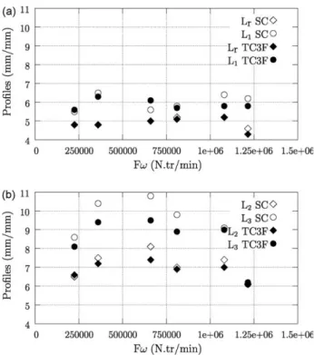
It is difficult to distinguish the results by rotational or welding speed or also by weld pitch for both pins though the characteristic lengths L2 and L3 were found toslightly
increase and then decrease when increasing ω (Tab.1). Figure 3 shows the characteristic lengths versus the product of the plunge force F and the rotational speed ω. For both pins, Lr, L1 do not change significantly with Fω.
However, we found that L2 and L3 increase and then
decrease when increasing Fω (Fig. 3). Though Fω is not an energy, this quantity combines the role of the plunge force and of the rotational speed on contact and frictional heating at the shoulder/plate interface. The plunge force affects the contact area between the shoulder and the
material. The rotational speed affects the frictional heating. The rotation of the shoulder on the top surface causes the temperature, near the shoulder/plate interface, to be higher than the temperature near the bottom surface. So the material near the top surface becomes soften and easier to be stirred. Thus, the shoulder dominated zone extends over the plate thickness when Fω increases. This result is confirmed by numerical simulations performed by Zhang and Zhang [3, 4] who simulated a welding thin plate of 3mm, similar to the current present experimental works. They found that the temperature is higher and more uniform with increasing the rotation speed and/or the external work applied on the numerical FSW system. The subsequent decrease of L2 and L3 with Fω is attributed to two main reasons
assuming that the plunge force is high enough to insure a wide contact with the shoulder.
1. As the workpiece is heated, localized relative softening and/or local melt may occur reducing friction and the heat generation rate [5, 6]. As a result, the shoulder dominated zone is thinner. 2. As the workpiece is heated, strong material softening
may occur. As suggested by Colegrove and Shercliff [7], this localizes the deformation and reduces the deformation region size.
Figure 3: Influence of F on L2 and L3
Note that the last line of Table 1 corresponds to the highest of Fω. The associated value of ω is 1620 rpm (the highest one) but the plunge force was taken quite low (750 kg) and clearly do not insure a firm contact with the top surface. Thus, the momentum transport from the rotating shoulder is not high enough to drive the material flow.
Thus, to sum up, the impact of the shoulder results from two effects: a thermal effect relating to the frictional heating and a mechanical effect related to the capacity of the shoulder to drive the flow. The mechanical effect is related to the material behavior but also to the contact area between the shoulder and the plate.
Interestingly, L2 and L3 are higher for the SC pin than for
the TC3F pin whereas Lr, L1 are nearly identical. These
results reveal that the joint profile evolves more abruptly along with the plate thickness when using the tapered cylindrical pin with three flats. In other words, the upper shoulder dominated zone is thinner when using the TC3F pin than when using the SC pin.
3.2 Analysis of the material flow path using thin foil of copper as tracers
Visualisation of material movement was observed by inserting a copper foil along the longitudinal seem side of the panels. We observe that the thin sheet of copper is cut in several pieces (Fig. 1). Though the copper sheet was initially placed in weld centreline, some pieces are found in both side of the joint line. In the upper portion of the weld, we observe that the copper pieces are in the advancing side (AS) quite far from the weld centreline whereas they are in the retreating side (RS) in the lower
portion and closer from the centreline. It is worth
noticing that the thin sheet of copper follows the shape of the weld at the AS. Fratini et al. [8] found similar observations for very equivalent friction stir welding conditions conducted in a 3mm thick aluminium alloy plate using a straight cylindrical pin.
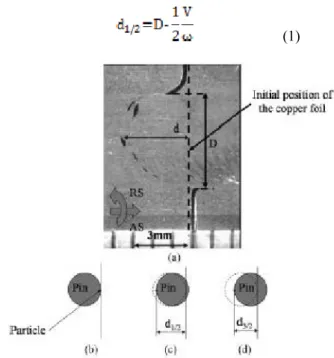
Visualisation of material movement was also observed by inserting a copper foil along the transverse seem side of the panels. Figure 4 shows a typical plan section in the lower portion of the weld (at 3.9mm from the plate surface). We observe that the copper foil is cut in small pieces which are behind the tool and more or less far from the initial foil position along the joint line. A part of foil initially on the AS is carried forward with the motion of the tool. At the RS of the weld, the foil is observed backward relative to the tool motion. This behavior is consistent with that observed in other experimental studies [9-11] and numerical simulations [12]. The distance D (Fig. 4) corresponds more or less to the diameter of the pin for plan sections at the bottom of the weld. Maximal position, d, denotes the highest measured distance between the initial position of the copper foil and the maximal position of a copper piece found behind the tool (Fig. 4). It was systematically estimated from macro-sections and compared to the distance d1/2 (Tab. 2). d1/2 is a hypothetic distance of a
particle estimated by the following procedure. Let us assume that a particle of the copper foil in the weld centreline initially in contact with the pin remains in contact with the pin during the rotation. In other words, we assume no sliding between the pin and the material
point. Let us now assume that this particle is deposited after a half revolution of the tool. The particle would be deposited at d1/2 behind the pin. d1/2 is calculated by
Equation (1).
(1)
Figure 4: Macro-section parallel to the plan section of the weld joint, at the weld root with a transverse copper foil (a) experimental observation, (b) initial position of particle, (c) position after a half a revolution and (d) position after a revolution and a half.
Table 2: Characteristic distances for the joint obtained with various process parameters (V, F, ω) deduced from observations of the weld root with transverse copper foil.
The maximal distance d was systematically found smaller than d1/2. This result means that either the
particles traveled several times around the rotating pin as confirmed by other literature experiments (see e.g. [9]) and two-dimensional numerical studies (see e.g. [7]) or there is a sliding between the particles and the pin as suggested by the three-dimensional numerical results presented by Zhang et al. [13]. Note that both phenomena can occur.
In addition, the maximal position d is found nearly constant, irrespective to the welding parameters but is larger in TC3F pin case than in SC pin case. This result is attributed to the higher radius of action of the TC3F pin with respect to the SC pin. Indeed, the presence of flats creates a natural eccentricity which increases the volume of interest of the stirring action [14-15]. As a result, the radial movement of the marker is larger. Fratini et al. [8] related such an effect comparing the stirring action between cylindrical and tapered pins. In addition, the pulse action generated by the TC3F pin is expected to increase the strain rate for a greater amount of material [7]. The higher strain rate for a greater amount of material increases the temperature which may result in a material softening. This localizes the deformation and reduces the deformation region size. Thus, L2 and L3 are smaller for the TC3F pin than for the
SC pin, despite it involves a larger radial movement for two possible reasons: (1) the three flat faces change the material flow generated by the shoulder and so reduces the thickness of the shoulder dominated zone and (2) the high strain rates and the resulting heating produce a material softening, this localizes the deformation.
4 CONCLUSIONS
The material flow during the FSW of thin plates was analysed when using unthreaded pins. Both pins have or do not have flat faces. Material flow with unthreaded pin was found to have the same primary features as material flow using classical threaded pins. The shoulder and in particular the frictional heating play a key role on the material stirring. The presence of flat faces on a pin creates a pulsating action which changes the flow generated by the shoulder and consequently reduces the role of the shoulder.
ACKNOWLEDGEMENT
The authors wish to acknowledge Institut de Soudure for financial and experimental support and Conseil Régional de Lorraine for financial support for this work. It was performed within the framework of the FSLOR project.
REFERENCES
[1] Lorrain, 0., Favier, V., Zahrouni H., Lawrjaniec D., Understanding the material flow path of friction stir
welding using unthreaded tools, Journal of
Materials Processing Technology,
doi:10.1016/j.jmatprotec.2009.11.005.
[2] Mishra, R.S., Ma, Z.Y., Friction stir welding and processing, Materials Science and Engineering 50, 1–7, 2005.
[3] Zhang, Z., Zhang, H.W., A fully coupled thermo-mechanical model of friction stir welding, International Journal of Advanced Manufacturing Technology 37, 279–293, 2008.
[4] Zhang, Z., Zhang, H.W., Numerical studies on controlling of process parameters in friction stir
welding, Journal of Materials Processing
Technology 209, 241–270, 2009.
[5] Elangovan, K., Balasubramanian, V., Influence of pin profile and rotationa speed of the tool on the formation of friction stir processing zone in AA2219
aluminium alloy, Materials Science and
Engineering, A 459, 7–18, 2007.
[6] Nandan, R., Debroy, T., Bhadeshia, H.K.D.H., Recent advances in friction-stir welding—Process, weldment structure and properties, Progress in Materials Science 53, 980–1023, 2008.
[7] Colegrove, P., Shercliff, H.R., CFD modelling of friction stir welding of thick plate 7449 aluminium alloy. Science and Technology of Welding and Joining 11, 429–441, 2006.
[8] Fratini, L., Buffa, G., Palmeri, D., Hua, J., Shivpuri, R., Material flow in FSW of AA7075-T6 butt joints: continuous dynamic recrystallization phenomena, Journal of Engineering Materials and Technology 128, 428–435, 2006.
[9] Guerra, M., Schmidt, C., McClure, J.C., Murr, L.E., Nunes, A.C., Flow pattern during friction stir welding. Materials Characterization 49, 95–101, 2003.
[10] Liechty, B.C., Webb, B.W., The use of plasticine as an analog to explore material flow in friction stir
welding. Journal of Materials Processing
Technology 184, 240–250, 2007.
[11] Reynolds, A.P., Seidel, T.U., Simonsen, M., 1999. Visualization of material flow in an autogenous friction stir weld. In: Proceedings of the 1st
Internationnal Symposium on Friction Stir Welding,
Thousand Oaks, California, USA, 1999.
[12] Xu, S., Deng, X., A study of texture patterns in friction stir welds. Acta Materialia 56, 1326–1341, 2008.
[13] Zhang, H.W., Zhang, Z., Chen, J.T., 3D modeling of material flow in friction stir welding under different process parameters, Journal of Materials Processing Technology, 183, 62–70, 2007.
[14] Thomas, W.M., Nicholas, E.D., Friction stir welding for the transportation industries. Materials and Design 18, 269–273, 1997.
[15] Elangovan, K., Balasubramanian, V., Influences of tool pin profile and tool shoulder diameter on the formation of friction stir processing zone in AA6061 aluminium alloy. Materials and Design 29, 362–373, 2008.