HAL Id: hal-01630247
https://hal.archives-ouvertes.fr/hal-01630247
Submitted on 14 Dec 2017
HAL is a multi-disciplinary open access
archive for the deposit and dissemination of
sci-entific research documents, whether they are
pub-lished or not. The documents may come from
teaching and research institutions in France or
abroad, or from public or private research centers.
L’archive ouverte pluridisciplinaire HAL, est
destinée au dépôt et à la diffusion de documents
scientifiques de niveau recherche, publiés ou non,
émanant des établissements d’enseignement et de
recherche français ou étrangers, des laboratoires
publics ou privés.
Production of composite particles using an innovative
continuous dry coating process derived from extrusion
Fanny Cavailles, Romain Sescousse, Alain Chamayou, Laurence Galet
To cite this version:
Fanny Cavailles, Romain Sescousse, Alain Chamayou, Laurence Galet. Production of composite
par-ticles using an innovative continuous dry coating process derived from extrusion. Advanced Powder
Technology, Elsevier, 2017, 28 (11), p.2875-2885. �10.1016/j.apt.2017.08.014�. �hal-01630247�
Production of composite particles using an innovative continuous dry
coating process derived from extrusion
Fanny Cavaillès, Romain Sescousse, Alain Chamayou, Laurence Galet
⇑Centre RAPSODEE, UMR CNRS 5302, Université de Toulouse, Ecole des Mines d’Albi-Carmaux, Campus Jarlard, 81013 Albi CT Cedex 09, France
Keywords: Dry particle coating Continuous process Twin-screw extrusion Wettability Talc
a b s t r a c t
Dry particle coating is used to modify surface properties and monitor the end use properties of powders. These processes are mainly running in batch mode. In certain cases, continuous processes may present interest for specific applications (limitation of investments, stability, versatility. . .). In this study, the fea sibility of dry coating particles by an innovative way derived from the well known extrusion process was investigated. Adhesion between host and guest particles is induced by mechanical shear stress during processing. A preliminary parametric study on microcrystalline cellulose particles as host particles was carried out in order to determine the operating condition range. Then, coating was successfully per formed using talc and a microcrystalline cellulose system, which demonstrates the feasibility of this novel process and led to different morphologies according to the operating conditions.
1. Introduction
Numerous industrial areas (Pharmacy, Biology, Food, Fertilizers, Minerals, Materials, Inks industries. . .) require to transform or to produce powdered materials. In such activities, coating processes (dry particle coating in particular) are used for monitoring several end use properties of the obtained composite particles[1].
Dry particle coating processes employ coating agents in partic ulate solid form. These particles, generally called ‘‘guest particles” (0.1 50
l
m size) are located onto the surface of ‘‘host particles” (1 500l
m size) by means of mechanical actions provided by the process. In a first step relatively stable structures (ordered mixing) are obtained due to the Van der Waals or electrostatic interactions. In a second step, the mechanical forces act, according to the phys ical/mechanical properties of the involved materials, to increase the surface adhesion modifying the composite particles. This forms new structures varying from discrete coating bound or embed ded guest particles to continuous film coating[1] mono or mul tilayer coating[2]. The main interest of such processes compared to wet and melt coating is to avoid the use of solvents and subse quent heating and drying steps. These points rank dry coating as an economically efficient and environmentally friendly process: energy costs are reduced as well as organic solvent emission and toxicity risks linked to residual solvent or binder. Moreover, therisk of product degradation due to heating of materials is avoided as well.
Many examples of dry coating applications are mentioned in the literature concerning food, cosmetic or chemical industries: for example controlled release, flame retardant, protection of materials against humidity, oxidation or oil absorbed, improve ment of dispersibility, taste, and odour. Owing to their wide inter ests, composite particles find their place also in the pharmaceutical industry. For instance they can be used to mask the flavour of active pharmaceutical ingredient (API), to produce dry powder inhaler carrier and to improve their properties, to control the sur face properties or end uses properties such as flowability[3], air or liquid dispersibility[4], bulk density[5], wettability[3,6,7].
In the current literature, different dry coating processes, gener ally based on devices diverted from their traditional use, are men tioned [1,8]. For example, Hybridizer, Mechanofusion and Mechanomill processes are some advances of grinding machines or Cyclomix![9 11], are used for dry particle coating. New mixers
are used for coating, such as the resonant acoustic mixer (RAM) in which an acoustic field spreads to provide the necessary energy for coating[12]. During the past five years, several researchers have realized processes that can simultaneously achieve multiple func tions, such as milling and coating. Fluid energy mills (FEM) allow micronization of particles thanks to compressed air or gas[13]. This kind of process has been developed in the pharmaceutical field to increase the specific surface and dissolution rate of API. Nevertheless, this single operation often leads to a decrease of
⇑Corresponding author.
flowability due to a relatively strong cohesion between fine parti cles. To solve this problem, API may be coated with glidants (as nanosilica or talc) to improve various properties: packing density
[3], flowability [3,14], de agglomeration or dispersion [15]. Han et al.[7]have micronized and coated ibuprofen with hydrophilic nano silica in order to produce a formulation for direct compres sion. They show that the API flowability, bulk density and com pressibility are improved after milling and coating by FEM compared to the uncoated API. An additional process step, a premixing between the guest and host particles, is necessary to allow an increase of the flowability in the feeder or a better coating efficiency in the FEM process[16].
All the previous mentioned processes are batch processes, which are time consuming, with limited productivity, and so economically less favourable than continuous processes [17]. Moreover, continuous processes allow a decrease of material handling and avoid scale up problems [18]. They allow greater flexibility concerning products and volumes with a limited product rejection[19]. Concerning the dry particle coating processes, some recent studies have employed a continuous co milling process in order to improve the API or pharmaceutical excipient performances [3,20,21]. The co milling processes are generally used for size reduction and improvement of various properties: flowability, tabletability [5,21,22]. These processes require the pre mixing of particles in order to obtain the desired properties.
The originality of the present work is to study the possibility to perform dry particle coating in a continuous process using twin screw extruder, which could provide major advantages. In pharma ceutical industries, the flexibility and polyvalence of processes are of great interest. In this case, the possibility to use an existing extruder in order to produce in a continuous way, a significant amount of composite particles is a significant advantage independently of the initial investment. Extrusion is widely used in polymer industry for shaping thermoplastics polymers or for compound formulation. In the pharmaceutical industry, this pro cess allows the production of solid dispersion: an API is usually molecularly dispersed in a water soluble polymer in order to enhance its solubility. Extrusion can also be found for food process ing (cereals, pastas, cheese etc.). Due to the flexibility of screw con figurations, temperature and pressure control, extrusion processes offer a variety of applications.
In conventional use, feed materials in powder, granule or pellet form are introduced through a hopper and are conveyed by the rotation of a single or twin screw in a heated barrel. During the transport, the matter is melted and mixed and finally forced through a die. Such a process exposes treated materials to high levels of shear stress and may also be adapted in an innovative way to a continuous dry particle coating process. A co rotative twin screw extruder without a die could also be employed as a dry coating device. The aim of this work is to study and to demon strate the feasibility of dry particle coating using a twin screw extrusion derived process.
As particle breakage is an important issue in pharmaceutical drug powders or cosmetics, this may be performed by choosing operating conditions with enough shearing to perform coating but soft enough to avoid particles damaging, particularly in case of brittle host particles which could be broken by the process. A preliminary study on the effect of operating conditions on particles will always been required.
We avoid the use of abrasive materials (example: nano siliica particles[21]) according to the recommendation of the equipment provider. This exploration and innovative work was for a particle couple well known as excipients in the pharmaceutical industry: cellulose/talc, and previously used in batch process[23]. We chose to highlight the influence of process parameters on the coating
quality for this couple of particles in order to test the coating method.
Microcrystalline cellulose granules (Cellet!) were chosen as
host particles. These particles display a high abrasion resistance and biocompatibility. They are commonly used in pharmaceutical industry as an excipient for controlled release formulations
[24 26]. Cellet! particles were also studied as an adsorbent for
removing dyes in water treatment [27]. Talc was chosen as the guest particles. It is employed in the pharmaceutical industry as an anti sticking agent for tablet production[28]and as a dermato logical protector[29]. Both materials are nonabrasive, which is important to avoid damaging the equipment.
These materials are interesting both in regard to their industrial applications and to their physico chemical differences. Composi tion difference leads to a favourable contrast for scanning electron microscopy (SEM) observations and Energy Dispersive X ray mea surements. The difference in surface properties (hydrophilic and hydrophobic behaviour for cellulose and talc respectively) allows the wettability as an end use characterization depending on the quality of the coating.
The first part of this paper focuses on the impact of the operat ing conditions, screw configurations and rotation speed, on the host particles morphology. The second part concerns the produc tion of composite particles using such a process to perform dry coating. Influence of screw rotation speed on coated particles was also examined.
2. Material and methods 2.1. Materials
Cellet!particles (microcrystalline cellulose provided by Phar
matrans Switzerland, Cellet!100) were used as host particles. They
display a narrow size distribution range from 100 to 200
l
m, with a 160l
m median size (DH) and a 1.47 g cm 3solid density (q
H).The talc used as guest particles is Talc00 lamellar magnesium sili cate Mg3Si4O10(OH)2powder from Luzenac quarry, France, with a
12
l
m median size (DG) and a 2.82 g cm 3solid density (q
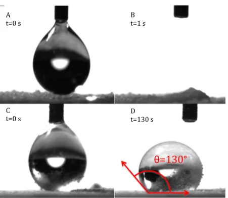
G). Seepart2.3. for characterization methods. SEM images of raw materi als are shown inFig. 1.Fig. 2shows images of a water drop on the surface of Cellet!and talc particles as a function of time. On the
pure Cellet!particles, the water drop takes less than 1 s to be com
pletely absorbed, showing the high hydrophilic property of this cellulosic material. On the contrary, after deposition, the water drop is very stable on the bed of talc particles for several minutes demonstrating its hydrophobic property with a contact angle of 130" (Fig. 2D). To illustrate those two different water affinities of the materials and the water drop behaviours, videos are proposed assupplementary data (Appendix A). Description of measurement equipment is described in Section2.3.
2.2. Coating process
Dry particle coating has been carried out using a co rotative twin screw extruder Pharmalab 16 (Thermo Scientific, Germany). This device is characterised by a 40:1 L/D ratio, where L (640 mm) and D (16 mm) are the length and the internal diame ter of the barrel respectively. The external diameter of the screws is 15.6 mm allowing an air gap of 200
l
m. Host particle size is small enough to allow their transport through the air gap and large enough to provide shearing in this region. Two gravimetric feeders (Brabender, Germany), with capacities of 0.05 2.5 kg and 0.5 10 kg, were used for guest and host particles respectively. These feeders are both placed upstream of the extruder screws. Screw configurations, composed of conveying elements andkneading blocks are totally flexible. Kneading blocks are composed of elliptic elements and the orientation between each elements can be adjusted at 30, 60 or 90" (seeFig. 3). Two types of kneading blocks were used in this study. The first one (A) was composed suc cessively of five elements at 30", three elements at 60" and four elements at 90". The second one (B), composed of successively three elements at 30", three elements at 60" and eight elements at 90" was designed to provide greater shear stresses than the first one. Screw configurations are shown inFig. 3where positions and compositions of A and B kneading blocks are represented. Knead
ing blocks are used for profile screws set up with Config. 2, Config. 3, Config. 4 and Config. 5, while screw Config. 1 was composed of conveying elements only. The barrel temperature was controlled at 22"C. The screw rotation speed was varied between 50 and 800 rpm. Downstream of the screws, the particles are directly col lected in a container without passing through a die.
After a preliminary study examining the effects of screw config urations and rotation speed on host particles alone, coating trials were carried out. In these experiments, Eq.(1)defines the intro duced mass fraction w of guest particles.
Fig. 1. SEM pictures of initial particles: Cellet!(left), Talc (right).
Fig. 2. Drop of pure water deposited onto the raw materials. Pure Cellet!particles: (A) t = 0 s, (B) t = 1 s and Talc particles: (C) t = 0 s, (D) t = 130 s showing a contact angle of
w mG
mGþ mH ð1Þ
where _mGand _mH are the feed mass flows (g/h) of guest and host
particles, respectively.
In order to obtain a full coverage, the mass fraction of guest par ticles should be superior to the one necessary for a monolayer cov erage, expressed by Eq.(2).
wmonolayer 1
1 þVHqH
NVGqG
ð2Þ
where VH,
q
H, VG,q
Gare volumes and solid densities of a single hostand guest particle respectively. N is the maximum number of guest particles coating a host particle’s surface for monolayer coverage. Considering the morphological approximation of spherical shape for host particles (diameter DH) and assuming lamellar disk mor
phology for guest particles (diameter DG), N can be expressed using
Eq.(3):
N $4C2DD2H
D2 G
ð3Þ
where C2Dis the 2 dimension packing fraction, corresponding to the
ratio of projected area of a guest particles monolayer on the avail able host particle surface.
Combining Eqs.(2)and(3), taking into account the morpholog ical assumption cited above, the mass fraction for a complete monolayer is approximately given by Eq.(4):
wmonolayer$ 1
1 þ DHqH
6C2dqGe
ð4Þ
For a random arrangement structure, C2D 0.82 according to
Thomas et al.[30]. In this study, host particles are microcrystalline cellulose, Cellet!, (
q
H 1.47 g cm 3; DH 160
l
m) while guest particles are composed of talc (
q
G 2.82 g cm 3). The thickness e oftalc particles is roughly estimated to 1
l
m according to SEM obser vations, corroborated by a previous work[31].Pre blending as been used by other authors for dry coating stud ies[21]. In our case, to ensure a continuous mixing and to avoid a possible effect on the particle arrangement (ordered mixture or coat ing during the pre blending process), a premix solution was rejected to highlight the specific action of the extrusion process.
The guest particle feed rate has been fixed close to the lower limit of the feeder (220 g/h), while the host particle feed rate has been fixed to a standard value of 1000 g/h according to preliminary stud ies. Consequently, the mass fraction of guest particles is 18%. This ratio is high compared to the above approximation (Eq.(4)) for com plete monolayer coverage (5%). Several coating experiments were carried out using operating conditions summarized inTable 1. 2.3. Particles characterization
2.3.1. Solid density measurement
Solid densities of raw materials (
q
Handq
G) were determinedby helium pycnometry using an AccupycII 1340 device (Micromeritics!, USA).
2.3.2. Particle size distribution
The particle size distributions (PSD) of uncoated and coated samples were determined by laser diffraction using a Mastersizer 2000 device (Malvern Instruments!, UK). This apparatus is equipped Fig. 3. Set-up of screw elements, kneading blocks and configurations used. Direction of processing: from right to left.
with a Sirocco dry powder feeder unit. Controlling the air pressure in a Venturi system ensures the dispersion of the powder. The method can be qualitative and comparative concerning the coating strength. Indeed, Vilela et al.[32]demonstrated that an increase of dispersion pressure can lead to removal of guest particles on the host particles surface. In this work, two levels of dispersion pressures were used: 0.5 and 3.5 bar. The obscuration varied between 2% and 6% to ensure the quality of the measurement. The results are expressed as volume and number distributions.
2.3.3. Sieving step
Free or weakly attached talc were removed from composites by a sieving method in order to assess the efficiency of the process. Around 50 g of samples was sieved in a 80
l
m mesh plate vibra tory sieve shaker device (Retsch, Germany), with an amplitude around 2 mm during 10 min.2.3.4. Microscopy images and surface composition analysis
The morphology of uncoated and coated particles was observed using scanning electron microscopy (SEM), type XL30, Philips, cou
pled with an energy dispersive X ray (EDX) analyser to locate guest particles at the surface of treated particles. During this EDX analysis, the detection of Si and Mg elements confirms the presence of talc. 2.3.5. Wettability assessment using the sessile drop method
Surface wettability of the uncoated and coated Cellet!particles
was investigated using the sessile drop method (DSA30 goniome ter, Krüss). A 10
l
L drop of pure water is deposited onto the surface of a levelled layer of particles. The water drop behaviour on each sample is recorded using a camera (Camera Allied, Vision Technol ogy). Images are extracted as a function of time and when possible, the contact angle of the water drop is measured.3. Results and discussion
3.1. Process parameters: screw configuration and rotation speed A preliminary study evaluates the impact of the screw configu rations and rotation speed on the host particles (size, morphology, damage, abrasion. . .), without the presence of guest particles.
Table 1
Operating conditions and particle characterizations. Powders Feeder flow (g/h) Screw rotation
speed (rpm)
Screw configurations
Introduced guest particles mass fraction w (%)
Particle characterizations
Cellet! Talc Before sieving After sieving
Cellet! 1000 – 100, 200, 400, 800 N"1–2–3–4–5 – SEM, PSD –
Cellet!/Talc 1000 220 50, 100, 150 N"1–4 18 PSD, SEM SEM, EDX, PSD, wettability
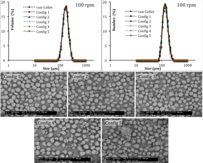
Four rotation speeds are studied as well as five screw configura tions (seeTable 1).Figs. 4 7present SEM pictures and PSD of Cel let! processed in the extruder as a function of the screw
configurations at 100, 200, 400 and 800 rpm respectively. For a 100 rpm rotation speed,Fig. 4indicates that the processed particles show the same PSDs (volume and number) as raw Cellet!
for every screw configuration. Nevertheless SEM pictures present slight damages on processed particles especially for Config. 5.
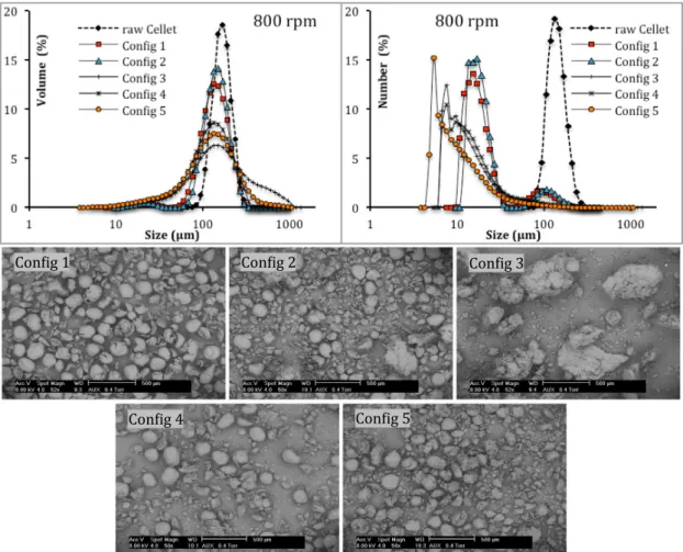
When the screw rotation speed increases, PSDs enlarge and are shifted towards the fine particles. This trend is slightly visible at 200 rpm: only particles processed from Config. 5 are affected (Fig. 5). From 400 rpm, this phenomenon is clearly pronounced (Figs. 6 and 7). All particles processed with kneading blocks are damaged, with an increase in the number and volume of fine par ticles, as can be seen by both the SEM pictures and PSDs. This latter is sensitive to the presence of fine particles. The bimodal number size distributions for Config. 3, Config. 4 and Config. 5 shows a sig nificant increase of fine particles content, confirming that particles have been damaged in the process. Below 400 rpm, conveying ele ments (Config. 1) doesn’t significantly affect PSDs. Config. 2 shifts the PSD towards smaller sizes keeping a monomodal distribution. At 800 rpm (Fig. 7), the damage phenomenon is intensified. All screw configurations provide a clear PSD shift towards the fine par ticles. Particles processed using Config. 1 and Config. 2 display bimodal number distributions while PSD of the other configura tions are monomodal with a larger content of fine particles (<10
l
m). Moreover, at 800 rpm, whatever the configurations,including kneading elements, particle agglomeration occurs during the process. These phenomena (not observed with conveying ele ments alone) are noticeable on both volume PSD and SEM images especially for Config. 3. These agglomerates are probably a conse quence of compression of fine particles in kneading zones.
Fig. 8displays all median diameters (d50from volume PSD) ver
sus rotation speed for the different configurations. It is noticeable that until 400 rpm, d50 decreases with rotation speed whatever
the configuration used. Moreover, the plots (up to 400 rpm) allow the classification of the configurations into three categories: con veying (Config. 1), 1 kneading zone (Config. 2, Config. 3 and Config. 4) and 2 kneading zones (Config. 5). For 800 rpm, d50values show
the occurrence of the agglomeration phenomenon for Config. 3. As conclusion of this parametric study, particle morphology is affected by an increase of shearing. This was provided by kneading elements and by the rotation of the screws. The more the screw rotation speed increases, the higher the shear rate will be, so the higher the shear stress endured by particles. This can lead to par ticle breakage. Concerning screw profiles, the more kneading ele ments are setting up on the screw, the more shearing effects are applied to the particles. Coupling these two operating conditions (high screw rotation speed and highly shearing profile screws con figuration) leads to intensify the friction forces between the parti cles and to their damage.
From the previous discussed results, we propose a classification of screw configurations according to their shearing effect, indirectly measured by their effect on particle size. The smallest
shearing effect undoubtedly occurs when using Config. 1 (convey ing elements only), followed by Config. 2, Config. 3 and Config. 4 are similar, while Config. 5 (two kneading blocks) provides the greatest shearing effect. The location of kneading blocks on profile screw (Config. 2 and Config. 3) seems to play a role as well as the angle between kneading elements and needs an in depth study.
Taking these observations into account, for these host particles, coating experiments could be carried out with a low shearing effect: rotation speed below 200 rpm and avoiding Config. 5 that induces damages at this rotation speed level.
3.2. Dry coating: influence of the screw configurations and rotation speed on the quality of the coated particles
Coating tests were performed using screw profile Config. 1 and Config. 4. For these configurations, the screws rotation speed val ues were fixed at 50, 100 and 150 rpm. The used mass fraction of guest fraction was fixed at 18%.
All processed particles display a bimodal size distribution by volume (not showed in this paper) whatever the applied air disper sive pressure (0.5 and 3.5 bar). The main peak of the bimodal dis tributions is centred on the raw Cellet!peak while the smallest
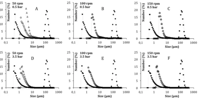
one is in the range of the raw talc size distribution. In order to com pare the efficiency of the coating, a focus on the fine particles is provided by the number PSD.Fig. 9displays number PSDs of com posites for three screw rotation speed values (50, 100 and 150 rpm) and two configurations (Config. 1, conveying and Config.
4, shearing). On each graph, the distributions of processed particles are comprised between host and guest PSDs. In the case of 100 rpm and 150 rpm, PSD from Config. 1 is strictly identical to the one from Config. 4 (Fig. 9B E) whatever the applied air dispersive pressure. For 50 rpm, PSD from Config. 1 and Config. 4 are distinct. When the applied air dispersive pressure increases from 0.5 to 3.5 bar, the distributions are shifted to the fine particles. This phenomenon can be explained by de agglomeration of free talc and/or detach ment of talc from Cellet!surface. It is noticeable that particles pro
cessed using Config. 4 and 50 rpm are the least sensitive to the size reduction when increasing the applied air pressure (Fig. 9A and B). Considering the hypothesis that size reduction with an increase of air dispersive pressure is caused by detachment of talc from Cellet!
surface, these operating conditions would lead to the more cohe sive talc/Cellet!structure. After sieving, number and volume PSDs
are completely superimposed to those of raw Cellet!regardless of
operating conditions and applied air dispersive pressure during measurement (Fig. 10). The sieving mechanical action is sufficient to separate free and weakly attached talc from Cellet! surface,
therefore no fine particles is detected even using a 3.5 bar air dis persive pressure. The mass fraction of retained talc after a sieving step is impossible to determine due to the crossing of talc and Cel let!PSDs; a significant amount of Cellet!falls through the sieve
meshes. Nevertheless, thanks to SEM pictures of sieved compos ites, a qualitative comparison of the coating efficiency can be done (Fig. 11). First of all, concerning the host particle’s morphology, only very few particle breakages are detectable for composites
produced with Config. 4 using 100 and 150 rpm (Fig. 11E and F). The number of damages is much less than the ones observed in the preliminary study at the same operating conditions (see
Fig. 4Config 4 andFig. 11E). Indeed, addition of talc in the system as guest particles leads to the diminution of damages due to its lubricant power [33]. Two different ways of talc (bright spots) repartition on the surface Cellet! can be highlighted. The first
one is a discrete heterogeneous repartition with a high level of talc concentration in some zones. This kind of repartition is observable
from 50 to 150 rpm (Fig. 11A C, E, F). The second one appears as a homogeneous continuous repartition given by Config. n"4 and 50 rpm, represented by the brightness of the particles shown in
Fig. 11D. In order to verify that the apparent homogeneous bright ness of this latter is not an artefact due to a contrast effect, a unique SEM sample was realized with particles obtained from 50 rpm, Config. 1 and Config. 4 (Fig. 12). EDX analysis mapping was also realized on this sample with silicon and magnesium ele ments, representative of talc presence and confirms homogeneous repartition of talc with Config. 4. SEM observations on a single composite particle highlight the difference of morphology for both operating conditions (Fig. 13). The contrast difference between talc and cellulose allows a clear distinction of the talc repartition beha viour on the cellulose surface. With Config. 1, talc is embedded in a discrete manner. The size of talc agglomerates reveals that talc par ticles are not dramatically altered (seeFig. 1for comparison). With Config. 4, the contrast on the particle surface is reduced compared to the previous one, which reveals a more homogeneous and con tinuous repartition. Talc seems to be delaminated and fill the sur face asperities. This measurement confirms our previous conclusion, Config. 4 and 50 rpm seem to be the best operating conditions to obtain a homogeneous talc repartition. This conclu sion can be explained by the fact that mixing elements, present on Config. 4, provide sufficient mechanical shearing to obtain a resistant coating. Even though increasing the screw rotation speed leads to an increase of shearing, which is favourable to a good adhesion, it also leads to a decrease in the particle’s residence time. As the particle’s residence time increases, more collisions occur
Fig. 7. Raw and processed Cellet!PSDs (volume and number) with corresponding SEM pictures. Process parameters: 800 rpm, Config. 1 to Config. 5.
Fig. 8. d50by volume of processed host particles for 5 screw configurations as
between host and guest particles, which leads to a more homoge neous talc repartition. An optimum has to be found between these two phenomena (shearing increase and residence time decrease) in order to obtain an optimal coating. For this talc/Cellet!system and
operating conditions studied, Config. 4 and 50 rpm appears to pro vide the most homogeneous repartition with the best adhesion of guest particles.
Fig. 14 shows images of a water drop on the surface of the Cellet!talc composite particles as a function of time. Concerning
the Cellet!particles coated with talc using Config. 1, the initial
image of the water drop (Fig. 14A) shows few particles inside the water drop. The water drop stays on the surface for a few seconds and penetrates the particle bed in 8 s (Fig. 14C). This behaviour con trasts to the case of pure Cellet!(Fig. 2B) and reveals a less hydro
philic surface of the coated particles. The images of the water drop deposited onto the coated particles processed with Config. 4 reveal
Fig. 9. PSDs by number of raw Cellet!(full diamonds), raw Talc (full squares), composites produced with Config. 1 (empty triangles) and Config. 4 (empty circles) using three
rotation speed values (50, 100, 150 rpm). Air dispersive pressure: 0.5 bar (A–C) and 3.5 bar (D–F).
Fig. 10. PSDs by volume and number (insert) of sieved composites, raw Talc and raw Cellet!. Air dispersive pressure: 3.5 bar.
a totally different behaviour. The water drop is very stable and an equilibrium state is reached beyond 130 s (Fig. 14F) with a contact angle value of around 120", revealing a hydrophobic surface. This effect is due to the complete covering of the Cellet!particles surface
with talc particles. To illustrate those two different water affinities of the composite materials and the water drop behaviours, videos are proposed assupplementary data (Appendix A).
4. Conclusion
An innovative way of dry particle coating based on extrusion derived process was studied. A preliminary study shows the
impact of process parameters (screw configurations and rotation speed) on single host particles morphology. The presence of several kneading elements on the screws associated to a high rotation speed provides strong shearing stress and leads to the damage of particles. A classification of the screw configurations used in this study was established according to their shearing capacity. A study with a more phenomenological approach of the elements types and positions should be interesting for a future work.
Talc coating onto microcrystalline cellulose particles was successfully performed and confirmed by SEM/EDX and PSDs measurements. The coating layers present discrete or continuous morphology depending on the operating conditions used
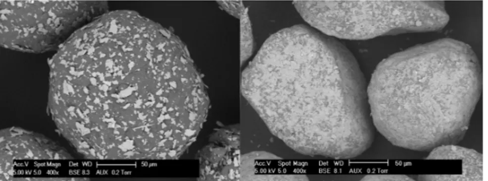
Fig. 12. SEM picture (left) of sieved composite particles produced with Config. 4 (top) and Config. 1 (bottom) using 50 rpm. SEM pictures coupled with EDX cartography analysis of silicon (middle) and magnesium (right) of the same sample.
Fig. 13. SEM pictures of Cellet!particle coated with Talc produced at 50 rpm, Config. 1 (left) and Config. 4 (right).
Fig. 14. Drop of pure water deposited onto the composite particles performed with Config. 1: (A) t = 0 s, (B) t = 5 s, (C) t = 8 s; and performed with Config. 4: (D) t = 0 s, (E) t = 5 s, (F) t = 130 s.
(configuration and screw rotation speed). The operating conditions leading to a relatively homogeneous and strong coating are inves tigated. As a complement to the above cited characterization tech niques, the efficiency of the coating was illustrated by a change of a macroscopic surface property: the wettability. Discrete coating reveals host like contact angle behaviour while homogeneous coating behaves similarly to the guest particles.
This study offers numerous perspectives for composite particle elaboration due to the process being continuous and highly flexi ble, the latter being especially apparent in regard to the tuning of stress levels.
Acknowledgments
The authors would like to acknowledge Christine Rolland for SEM pictures, Séverine Patry for wettability measurements and Benjamin Cowell for English reviewing.
Appendix A. Supplementary material
Four videos of water drop deposited onto the surface of a lev elled layer of particles: Cellet!, Talc, Composite from Config. 1
and Composite from Config. 4. Supplementary data associated with this article can be found, in the online version, athttp://dx.doi.org/ 10.1016/j.apt.2017.08.014.
References
[1]R. Pfeffer, R.N. Davé, D. Wei, M. Ramlakhan, Synthesis of engineered particulates with tailored properties using dry particle coating, Powder Technol. 117 (2001) 40–67.
[2] H. Ichikawa, T. Uemura, Y. Fukumori, Dry particle coating with polymeric nanopowders for fabricating multi-layered, prolonged-release microparticles using Theta-Composer, in: The 10th International Symposium on Agglomeration, September 2–4, 2013, Kobe, Japan.
[3]X. Han, C. Ghoroi, D. To, Y. Chen, R. Davé, Simultaneous micronization and surface modification for improvement of flow and dissolution of drug particles, Int. J. Pharm. 415 (2011) 185–195.
[4]P. Stewart, I. Larson, L. Qu, Q. Zhou, D. Morton, Surface modification of micronized drug powders to improve aerosolization via mechanical dry powder coating: Sciforum Electronic Conference Series, Proceedings of the 1st Electron. Conf. Pharm. Sci., 1–31 March 2011, 2011 (a004).
[5]M.P. Mullarney, L.E. Beach, R.N. Davé, B.A. Langdon, M. Polizzi, D.O. Blackwood, Applying dry powder coatings to pharmaceutical powders using a comil for improving powder flow and bulk density, Powder Technol. 212 (2011) 397– 402.
[6]A. Tilley, D.A.V. Morton, T. Hanley, B.J. Boyd, Liquid crystalline coated drug particles as a potential route to long acting intravitreal steroids, Curr. Drug Deliv. 6 (2009) 322–331.
[7]X. Han, C. Ghoroi, R. Davé, Dry coating of micronized API powders for improved dissolution of directly compacted tablets with high drug loading, Int. J. Pharm. 442 (2013) 74–85.
[8]M. Gera, V. Saharan, M. Kataria, V. Kukkar, Mechanical methods for dry particle coating processes and their applications in drug delivery and development, Recent Pat. Drug Deliv. Formul. 4 (2010) 58–81.
[9]A. Sato, E. Serris, P. Grosseau, G. Thomas, L. Galet, A. Chamayou, et al., Experiment and simulation of dry particle coating, Chem. Eng. Sci. 86 (2013) 164–172.
[10]Y. Ouabbas, A. Chamayou, L. Galet, M. Baron, G. Thomas, R. Grosseau, et al., Surface modification of silica particles by dry coating: characterization and powder ageing, Powder Technol. 190 (2009) 200–209.
[11]G. Lefebvre, L. Galet, A. Chamayou, Dry coating of talc particles with fumed silica: influence of the silica concentration on the wettability and dispersibility of the composite particles, Powder Technol. 208 (2011) 372–377.
[12]Z. Huang, J.V. Scicolone, X. Han, R.N. Davé, Improved blend and tablet properties of fine pharmaceutical powders via dry particle coating, Int. J. Pharm. 478 (2015) 447–455.
[13] J. Yang, R. Davé, C. Gogos, L. Zhu, M. Young, L. Fishbein et al., In-situ milling and coating within a fluid energy mill, in: Karlsruhe, 2006.
[14]Q. Zhang, J. Yang, S. Teng, R.N. Davé, L. Zhu, P. Wang, et al., In-situ, simultaneous milling and coating of particulates with nanoparticles, Powder Technol. 196 (2009) 292–297.
[15]C. Ghoroi, X. Han, D. To, L. Jallo, L. Gurumurthy, R.N. Davé, Dispersion of fine and ultrafine powders through surface modification and rapid expansion, Chem. Eng. Sci. 85 (2013) 11–24.
[16]Q. Zhang, P. Wang, S. Teng, Z. Qian, L. Zhu, C.G. Gogos, Simultaneous milling and coating of inorganic particulates with polymeric coating materials using a fluid energy mill, Polym. Eng. Sci. 50 (2010) 2366–2374.
[17]C. Vervaet, J.P. Remon, Continuous granulation in the pharmaceutical industry, Chem. Eng. Sci. 60 (2005) 3949–3957.
[18]H. Leuenberger, New trends in the production of pharmaceutical granules: batch versus continuous processing, Eur. J. Pharm. Biopharm. 52 (2001) 289– 296.
[19]L. Alinaghian, A. Ates, U. Bititci, T. Harrington, J. Srai, R. Talati, Drivers and barriers of continuous manufacturing in the pharmaceutical industry, 16th Camb. Int. Manuf. Symp., Cambridge, 2012.
[20]C. Knieke, M.A. Azad, D. To, E. Bilgili, R.N. Davé, Sub-100 micron fast dissolving nanocomposite drug powders, Powder Technol. 271 (2015) 49–60. [21]Z. Huang, J.V. Scicolone, L. Gurumuthy, R.N. Davé, Flow and bulk density
enhancements of pharmaceutical powders using a conical screen mill: a continuous dry coating device, Chem. Eng. Sci. 125 (2015) 209–224. [22]J. Yuan, L. Shi, W.J. Sun, J. Chen, Q. Zhou, C.C. Sun, Enabling direct compression
of formulated Danshen powder by surface engineering, Powder Technol. 241 (2013) 211–218.
[23]S. Otles, Modification of surface properties of biopowders by dry particle coating PhD, Université de Toulouse, 2008.
[24]G. Buchholcz, A. Kelemen, K. Pintye-Hodi, Modified-release capsules containing sodium riboflavin 50-phosphate, Drug Dev. Ind. Pharm. 40 (2014) 1632–1636.
[25]S.F. Hung, C.M. Hsieh, Y.C. Chen, C.M. Lin, H.O. Ho, M.T. Sheu, Formulation and process optimization of multiparticulate pulsatile system delivered by osmotic pressure-activated rupturable membrane, Int. J. Pharm. 480 (2015) 15–26. [26]N. Huyghebaert, A. Vermeire, P. Rottiers, E. Remaut, J.P. Remon, Development
of an enteric-coated, layered multi-particulate formulation for ileal delivery of viable recombinant Lactococcus lactis, Eur. J. Pharm. Biopharm. 61 (2005) 134–141.
[27]G.B.D. Suteu, Cellulose cellets as new type of adsorbent for the removal of dyes from aqueous media, Environ. Eng. Manage. J. 5 (2015) 525–535.
[28]P. Leterme, A. Gayot, G. Finet, M. Bizi, M.P. Flament, Influence of the morphogranulometry and hydrophobicity of talc on its antisticking power in the production of tablets, Int. J. Pharm. 289 (2005) 109–115.
[29]M.I. Carretero, M. Pozo, Clay and non-clay minerals in the pharmaceutical and cosmetic industries: part II. Active ingredients, Appl. Clay Sci. 47 (2010) 171– 181.
[30]G. Thomas, Y. Ouabbas, P. Grosseau, M. Baron, A. Chamayou, L. Galet, Modeling the mean interaction forces between powder particles. Application to silica gel-magnesium stearate mixtures, Appl. Surf. Sci. 255 (2009) 7500–7507. [31]L. Godet, Broyage fin du talc par jets d’air opposés PhD thesis, Institut national
polytechnique de Lorraine, 2001.
[32]A. Vilela, L. Concepcion, P. Accart, A. Chamayou, M. Baron, J.A. Dodds, Evaluation of the mechanical resistance of a powder-powder coating by modulated dry feed particle size analysis, Part. Part. Syst. Charact. 23 (2006) 127–132.
[33]S.S. Dawoodbhai, H.R. Chueh, C.T. Rhodes, Glidants and lubricant properties of several types of talcs, Drug Dev. Ind. Pharm. 13 (1987) 2441–2467.