HAL Id: hal-01970072
https://hal.archives-ouvertes.fr/hal-01970072
Submitted on 4 Mar 2019
HAL is a multi-disciplinary open access
archive for the deposit and dissemination of
sci-entific research documents, whether they are
pub-lished or not. The documents may come from
teaching and research institutions in France or
abroad, or from public or private research centers.
L’archive ouverte pluridisciplinaire HAL, est
destinée au dépôt et à la diffusion de documents
scientifiques de niveau recherche, publiés ou non,
émanant des établissements d’enseignement et de
recherche français ou étrangers, des laboratoires
publics ou privés.
Biofuel emulsifier using high velocity impinging flows
and singularities in micro-channels
A. Belkadi, A. Montillet, J. Bellettre
To cite this version:
A. Belkadi, A. Montillet, J. Bellettre. Biofuel emulsifier using high velocity impinging flows and
singularities in micro-channels. ASME 2016 Internal Combustion Engine Division Fall Technical
Conference, Oct 2016, Greenville, United States. �10.1115/ICEF2016-9314�. �hal-01970072�
BIOFUEL EMULSIFIER USING HIGH VELOCITY IMPINGING FLOWS
AND SINGULARITIES IN MICRO-CHANNELS
A. Belkadi
LTN (UMR CNRS Univ. Nantes 6607), 1 rue Christian Pauc, BP 50609,
44300 Nantes, France
A. Montillet
GEPEA (UMR CNRS EMN ONIRIS Univ. de Nantes 6614), 37 bd de l'Université,
44600 Saint-Nazaire, France J. Bellettre
LTN (UMR CNRS Univ. Nantes 6607), 1 rue Christian Pauc, BP 50609,
44300 Nantes, France [email protected]
ABSTRACT
The objective of this work is to design an original microfluidic mixer for continuous emulsification of small fractions of water in a lipid phase. This system is aimed to be integrated on-line in the process so as to avoid the use of a surfactant. The targeted application is a better combustion of alternative biofuels in boilers, turbines or internal combustion engines in general. The developed micro-system which includes impinging flows and elbows, is performed on the basis of a specific design of micro-channels, adapted to the respective flow rates and the characteristics of the fluids to be emulsified (viscosity, surface tension). The variation of different parameters is tested in this study such as the nature of the lipid phase (viscosity, density, surface tension and components), the length of micro-channels in the elbow and the flow rate of the dispersed phase. The dispersion of water is much more efficient with this microsystem using gasoil rather than vegetable oil as the continuous phase.
INTRODUCTION
For the sake of a less polluted environment and the necessity of enhancing efficient consumption of energy, alternative fuels have to be developed and their combustion has to be improved. Some studies [1-5] show that the presence of a low fraction of
finely dispersed water (droplets of the order of 5 to 10 µm) in the fuel lowers the combustion temperature and thus reduces emissions of polluting gasses and particles matters resulted from poor combustion. In this objective, the use of water as a dispersed phase in liquid biofuels is commonly promoted. The emulsified fuel is intended for powering internal combustion engines, turbines and boilers. The dispersed water plays a key role in a phenomenon called micro-explosion, where both thermal and mechanical effects allow optimizing combustion and reduction of emissions of polluting gases and particles. The ambition of this study is to provide a continuous emulsification system dedicated specifically to water in oil emulsification. The final applications concern the field of energy conversion, such as boilers, turbines or internal combustion engines in general. The continuous phase can be made of various sources such as petro-diesel, heavy fuel or lipid waste (waste vegetable oils, animal fats). The difficulties related to the envisaged applications are numerous such as the characteristics of the used fluids, their volumetric ratio in the emulsion and the need to design a compact process to treat sufficient flow rates for the energy plans target. This work was directed towards the proposal of a system based on the use of sub millimeter-sized channels (Dh < 1 mm). Research in the field of microfluidics is very active for two decades and shows particular interest for the development of
Proceedings of the ASME 2016 Internal Combustion Engine Fall Technical Conference ICEF2016 October 9-12, 2016, Greenville, SC, USA
emulsification processes [6, 7]. The state of the art literature shows a significant number of studies dealing with emulsification processes, mainly applied to oil in water mixtures (o/w) [8, 9]. Unquestionably, emulsification of water in oil (w/o), which is treated in this work, is more seldom studied as it requires optimization from an energy point of view.
Two main reasons explain it: the continuous phase exhibits a viscosity which is, generally, several decades higher than that of the water. The ratio of the flow rates for the two phases is such that the emulsification process is consuming much more energy with w/o emulsion than o/w ones.
Generally, the maximal fraction of water that can be included before catastrophic inversion with w/o emulsions is about 20% [10-12].
In particular, concerning the targeted applications, literature points out that small fractions of water (10% or less) are needed [3-5].
A test facility was developed in this work in the aim to test the studied micro-systems in the emulsification conditions corresponding to the final applications (fluid properties and flow rates involved). During these tests, water was used as the aqueous phase in small amounts, not exceeding a fraction of 20 %. Sunflower oil or gasoil are tested as the continuous phase. Because of economic and environmental concerns related to the intended final application for this emulsification process (combustion), no surface agent is used.
EXPERIMENT AND PROCEDURES Experimental facility
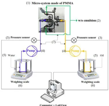
The used test bench is shown in Figure 1. This installation is equipped with double piston displacement pumps (ARMEN - APF-100-251, see Figure 1 - (4)). The maximum working pressure and flow rate of these pumps are respectively 25 bar and 100 ml/min (maximum speed available in the case of the use of water).
In order to measure the flow rates versus time, the experimental set-up is equipped with two weighing scales Sartorius - MSE2203 (see Figure 1 - (6)) allowing a continuous acquisition of measured mass with an accuracy of ± 10-3 g. The
pressure measurement is ensured by two compact pressure transmitters Gems-3100. The measuring range of pressure sensor 0 - 25 bar with an accuracy of ± 0.25% of full scale. The pressure sensors are connected to the emulsification loop between the pump and the inlet of the micro-system (Figure 1 - (3)). The sensors measure the relative and static pressure for each of the two mixed phases. Connections between the pumps and the micro-system are made using fluoropolymer tubes (FEP) with an inner diameter (ID) of 1.55 mm and an outer diameter (OD) of 3.125 mm.
High speed visualization
For the purpose of analyzing the flow prevailing in the microsystem, a high speed visualization using “LaVision HighSpeedStar 6” camera is implemented.
Figure 1. Emulsification setup: (1)- Micro-system comprising a single bend at the emulsion channel, (2)- Water in oil emulsion, (3)- Pressure sensors, (4)- Piston pumps, (5)- Beakers containing water or continuous phase (oil or Diesel), (6)- Weighing scales, (7)- Fluoropolymer tubes (FEP) with ID = 1.55 mm and OD = 3.125 mm.
Characteristics of the used fluids
The main characteristics of the fluids are recapped in Table 1. Sunflower oil and gasoil are respectively used as the continuous phase. It may be noticed that the viscosity of Sunflower oil at the ambient temperature is closed to that of heavy fuel at a temperature of about 60°C.
Table1. Main characteristics of the used fluids.
Liquids characteristics at 25 °C Density Surface tension Viscosity ρ [kg/m3] σd/c / [mN/m] µ [mPa.s] Tap water 998 72 1 Sunflower oil 864 33 52.2 Gasoil 823 23.8 17.7
Interfacial tension (IFT) σwater/oil 27.6 mN/m
σwater/gasoil 25 mN/m
Control of emulsification quality
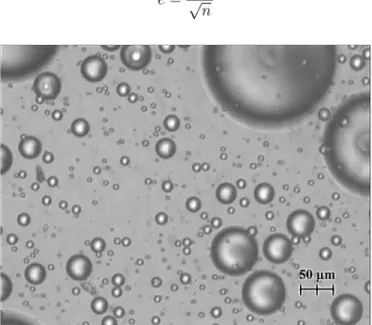
The quality of dispersion is checked using optical microscopy techniques. At each test, a sample of emulsion, is immediately analyzed (Figure 2) on a hemocytometer cell type made of PolyMethyl MethAcrylate (PMMA). Convergence of the statistics regarding mean diameter, d10, and its standard error,
exp, are controlled as the function of the number of analyzed
The mean diameter d10 is defined as following:
Where “n” is the number of analyzed droplets di.
The expression for the experimental standard deviation, calculated for each size diameter, is given by the formula:
The arithmetic uncertainty for each mean droplet size calculation is given below:
Figure 2. Example of water in sunflower oil dispersion under an optical microscope.
Dimensionless numbers
Dimensionless numbers are useful to compare the different flow regimes in our experiments. The following parameters are used to identify the relevant forces involved in the microchannel for the drop formation:
- The capillary number expresses the ratio of viscous forces and interfacial forces: Ca = µc vm / σd/c.
- The Ohnesorge number estimates the ratio of the viscous forces and the combination of inertial forces and interfacial forces. In the case of dispersion, it characterizes simultaneously the deformation and transport (advection) imposed by the continuous phase (vegetable oil or gasoil) on the dispersed phase (water): Oh = µc / (ρd d10σd/c)1/2.
- The Weber number is defined as the ratio of inertial forces on the interfacial forces: We = ρd vd2 dd / σd/c.
MICRO-SYSTEM FOR W/O EMULSIFICATION
The developed microfluidic device is composed of two slabs of PMMA, held together with screws. An O-ring is disposed between slabs in order to ensure the sealing. The micro-channels are machined on a single slab, the second one is used as a cover. The geometry and design of the microfluidic device core is presented in Figure 3. It consists of two crossing micro-channels featuring two inlet sections and two outlet sections. As shown in Figure 3, the channels have a square cross section and are designed to put oil and water streams in a head-on, impinging flow. The originality of the present work is that the section of water inlet is smaller than that of oil. In this configuration, an off-axis is responsible for the occurrence of a hydrodynamic structure called swirl [10].
As mentioned before, this micro-system is designed for continuous water in oil emulsification. One of the aims of this work is to study the influence of the fluid characteristics on the swirl. For this purpose, two liquids have been used as the continuous phase, respectively sunflower oil and gasoil.
In this work, a new original geometry is used, as shown in Figure 4, for which two different configurations are tested, respectively designated as (a) and (b). As formerly explained, both configurations offer a cross which is the seat of the frontal impact of two phases (dispersed and continuous phase). On each of the two channels of the emulsion is disposed one right bend. For both configurations, the cross section of the oil channel and emulsion channels is 600µm x 600µm. The cross section of the water channel is 300µm x 300µm. The only difference between the configurations (a) and (b) is the length. The distance between the intersection and the bend of configuration (a) is indeed two times longer than the same distance in configuration (b).
Figure 3. Design of the impinging zone localized in the crossing zone of the developed microfluidic devices [10].
Figure 4. Schematic representation of the two micro-fluidic configurations tested.
Result of dispersion
Table 2 summarizes the conditions and results of different tests obtained using the two configurations. Each series corresponds to a different flow rate of the dispersed phase while the flow-rate of the continuous phase is kept at the same order of magnitude for a given lipid phase. The pressure drop is respectively about 5 bars and 4 bars with configurations (a) and (b) using sunflower oil as lipid phase. Using gasoil, the pressure drop is respectively about 0.9 bar and 0.7 bar with the configurations (a) and (b). For each lipid phase, the maximal flow-rate available with the pump has been studied. This explains why the maximal flow rate with sunflower oil is lower than that of gasoil.
Table 2. Mean size of droplet determined in the dispersions obtained using the two different continuous phases.
Config. (a)
Sun
Flower Oil (QO - Qw) Gasoil (QG - Qw) d10 e [µm] [ml/min] d10 e
[µm] [ml/min] Series 1 32 ±0,29 (76.4 - 8.3) 23 ±0,22 (100 - 7.5) Series 2 27 ±0,25 (81 - 11.4) 15 ±0,19 (99.5 - 10.5) Series 3 19 ±0,19 (75.2 - 17.4) 13 ±0,18 (97.6 - 15.9) Series 4 19 ±0,18 (70.5-22.3) 12 ±0,18 (97.7 - 21) Config. (b) Sun
Flower Oil (QO - Qw) Gasoil (QG - Qw) d10 [µm] [ml/min] d10 [µm] [ml/min]
Series 1 43 ±0,55 (64.7 - 8.3) 12 ±0,15 (98.1 - 8.4) Series 2 35 ±0,38 (78.8 - 11.9) 12 ±0,14 (97.9 - 12.0) Series 3 23 ±0,18 (80.8 - 17.6) 11 ±0,17 (99.2 - 18.0) Series 4 29 ±0,16 (76.4 - 23.7) 8,5 ±0,14 (99.1 - 24.0)
An example of diameter distribution obtained (gasoil, configuration b, series 1) is plotted in the figure 5. The distribution of size is rather close to a log normal distribution, but it may be emphasized that the measurement of the diameter is limited by a physical cut off due to the use of an optical observation to characterize the droplets. Thus, droplets under 1-2 µm cannot be considered.
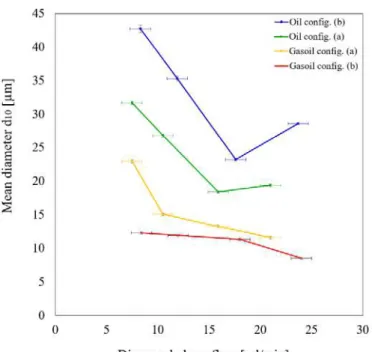
Figure 6 points out the effect of the continuous phase flow rate on the water mean diameter in the configuration (b). Mean diameter of droplets corresponding to the targeted range (5 to 10 µm) can be achieved with flow-rates of about 100 mL/min. Figure 7 allows comparing the performances of the two configurations using similar couples of lipid/water flow-rates. A better dispersion is obtained when using a continuous phase with a relatively low viscosity (gasoil). Compared to the results with configuration (a), it can be observed that shortening the length of channel is useful only with gasoil as continuous phase: mean diameters of droplets respectively obtained with the two configurations are not significantly different, except at the lowest water flow-rate studied. Concerning the sunflower oil phase, the efficiency of the configuration (a) is better, indicating an influence of the length of the channels on the dispersion.
Figure 5. water droplets distribution (gasoil, configuration b, series 1)
Figure 6. Influence of the flow-rate of the continuous phase flow on water droplets using configuration (b).
Table 3 recaps the covered ranges of the capillary number, weber number and Ohnesorge number. The level of the capillary number involved in this study is much higher than what is classically observed in the field of microfluidics. The values of the capillary number indicate that the viscous forces are higher than the interfacial ones in all the experiments. Concerning the inertial forces, they are mainly dominant compared to the interfacial ones at the higher flow-rates investigated. The variation of the Weber number in the studied range indicates that these experiments are implemented in a transitional flow regime. This is confirmed by the flow visualization experiments that are presented in the next section.
Figure 7. Influence of the dispersed phase flow on the mean size of water droplets.
Table 3. Explored range of dimensionless characteristic numbers using configuration (b).
Config. (b) Series 1 Series 2 Series 3 Series 4 Sunflower oil We 0.06 0.10 0.14 0.31 Oh 1.6 1.76 2.18 1.96 Ca 3.37 4.18 4.54 4.62 Gasoil We 0.02 0.04 0.08 0.10 Oh 1.01 1.03 1.05 1.22 Ca 1.75 1.80 1.92 2.02 FLOW VISUALISATION
As mentioned, an experimental investigation using a high speed camera was applied to investigate the flow at the crossing and the outlet of the crossing of the studied micro-system (configuration (b) shown in Figure 4). Images of this investigation are shown in Figure 8.
The flow of the continuous phase (vegetable oil or gasoil) is maintained as constant as possible. The dispersed phase flow rate is strongly varied in order to study the influence on the flow topology and on the size of water droplet.
These images are obtained without the use of particles seeds or liquids tracers. The interface of the dispersed phase (water) and the continuous phase naturally appears as black color, due to the interaction of incident light and water/oil interface. This phenomenon is explained by redirection of the incident light beam which locally produces extinction on this interface.
(a). QO = 64.7 ml/min Qw = 8.3 ml/min (e). QG = 98.1 ml/min Qw = 8.4 ml/min
(b). QO= 74.8 ml/min Qw= 11.9 ml/min (f). QG = 97.9 ml/min Qw= 12.0 ml/min
(c). QO = 80.8 ml/min Qw = 17.6 ml/min (g). QG = 99.2 ml/min Qw = 18.0 ml/min
(d). QO= 76.4 ml/min Qw= 23.7 ml/min (h). QG = 99.1 ml/min Qw= 24.0 ml/min
Figure 8. Flow topology for two different continuous phases using configuration (b).
The difference between the two configurations lies in the difference of the length of the sections of the outlet channels. Each straight section (respectively located before and after the bend) is divided by a factor 2 in the configuration (b) compared to configuration (a). It is observed in our experiments that a longer length is more benefit in the case of sunflower oil as the mean diameter of the emulsion is smaller with this configuration, but the opposite effect is observed with using gasoil as the continuous phase. The length of the channel can have an importance regarding coalescence phenomena and mixing. As no surfactant is used, coalescence which mostly happens in long straight channels has to be avoided. In this work, the shortness of the channels is limited by technical constraints (the use of a seal to avoid leakages) and then can hardly be smaller than 10 mm, as in configuration (b). Secondly, it can be observed that the tested design of the micro-channels, whatever is the length of the outlet channels, is more efficient using a less viscous fluid. In these microsystems, the mechanisms of water dispersion are mainly enhanced by the impact of the fluids, and subsequently by the development of roll structures generated by a step present in the cross. As the value of the interfacial tension is similar for the two couples of fluids tested, the nature of the flow pattern mainly depends on the viscosity of the fluid. A previous study [13] have shown that cross shape micromixers exhibit a good efficiency in mixing fluids of similar viscosities, particularly in the engulfment regime. This is observed in the present work in the case of the diphasic system gasoil/water (Fig. 8). In the case of sunflower oil/water diphasic system, the mixing of the two fluids is more difficult, thus roll structures persists along the outlet channels (Fig. 8) and the mechanism of dispersion is much less completed before the elbow than with the gasoil phase. At higher tested flow rates of water, intermittent structures which are Rayleigh instabilities can be observed (8.c and 8.d). These instabilities contribute to a better dispersion of water. The configuration (a) offers in this case a better development of these structures which leads to a better dispersion than in configuration b).
CONCLUSION
In the present work, an original liquid/liquid mixer is developed. This emulsifier is tested using two different continuous phase. Results show that emulsification with high velocity lipid phase flow allows the production of a fine emulsion (mean water drop diameter around 10 µm). Globally, a better dispersion of water is observed in the present study using gasoil as compared to vegetable oil. This study allows giving some indications concerning the design of micromixers for biofuels emulsification. The effect of the length of the channels has been studied in order to evaluate a possible lowering of the pressure drop while shortening them (configuration (b)). Using low viscous continuous phase like gasoil, the efficiency of the dispersion is not significantly increased using longer channels (configuration (a)) but the level of the pressure drop is relatively
low, then the interest of shortening the length of the channel remains limited.
On the opposite, the dispersion of viscous continuous phase is more efficient using longer channels. In this case, Rayleigh instabilities are developed within the flow. They need time and length to grow up and disperse the water.
Tests with other geometries and fluids are under progress and will further improve the quality and the diversity of the emulsion produced in micro-channel for fuel preparation.
NOMENCLATURE
µc viscosity of the continuous phase
vm mean velocity or the output emulsion velocity obtained
by the formula: vm = (Qc + Qd) / 2 Semul
Semul section of emulsion channel 600µm x 600µm
σd/c tension at the dispersed/continuous interface
σexp standard deviation
ρd dispersed phase density
ρc continuous phase density
dd hydraulic diameter of the inlet channel of the dispersed
phase (water)
d10 arithmetic average diameter of the emulsion
Qd dispersed phase flow rate
Qc continuous phase flow rate
Qw water flow rate
QO sunflower oil flow rate
QG gasoil flow rate
REFERENCES
[1] Jacques, M., Jordan, J., Williams, A. et Hadley-Coates, L., 1977, “The combustion of water-in-oil emulsions and the influence of asphaltene content”, Proceedings of the
Combustion Institute, Vol. 16, issue 1, pp. 307–319.
[2] Mura E., Josset C., Loubar K., Huchet G. et Bellettre J., 2010, “Effects of dispersed water droplets size in Micro-explosion phenomenon for water in oil emulsions”,
Atomization and Sprays, Vol. 9, pp. 791-799.
[3] Tarlet D., Bellettre J., Tazerout M, Rahmouni C., 2009. “Formulation and combustion of emulsified fuel: The changes in emission of carbonaceous residue”,
International Journal of Energy Research, Vol. 34, pp.
688–694.
[4] Attia A. M. a., Kulchitskiy a. R., 2014, “Influence of the structure of water-in-fuel emulsion on diesel engine performance”, Fuel, Vol. 116, pp. 703–708.
[5] Senthil Kumar M., Kerihuel A., Bellettre J., Tazerout M., 2006, “A comparative study of different methods of using animal fat as fuel in a compression ignition engine”. ASME
Journal of Engineering for Gas Turbines and Power, Vol.
[6] Zhao C.-X., Middelberg A. P. J., 2011, “Two-phase microfluidic flows”. Chemical Engineering Science, Vol. 66, issue 7, pp. 1394–1411.
[7] Schubert H. Ã., Engel R., 2004, “Product and formulation engineering of emulsions”, Chemical Engineering, Vol. 82, pp. 1137–1143.
[8] Nisisako T., Hatsuzawa T., 2009, “A microfluidic cross-flowing emulsion generator for producing biphasic droplets and anisotropically shaped polymer particles”
Microfluidics and Nanofluidics, Vol. 9, issue 2-3, pp. 427–
437.
[9] Kiss N., Brennn G., Pucher H., Wieser J., Scheler S. Jennewein H., Suzzi D., Khinast J., 2011, “Formation of O/W emulsions by static mixers for pharmaceutical applications” Chemical Engineering Science, Vol. 66, pp. 5084–5094.
[10] Belkadi, A., Tarlet, D., Montillet, A., Bellettre, J., Massoli, P., 2015, “Water-in-oil emulsification in a microfluidic impinging flow at high capillary numbers”, International
Journal of Multiphase Flow, Vol. 72, pp. 11–23.
[11] Nisisako T., Higuchi T., Torii T., 2002, “Formation of droplets using branch channels in a microfluidic circuit”
Proceedings of the 41st SICE Annual Conference - SICE02, Vol. 2, 957–959.
[12] Nisisako T., Higuchi T., Torii T., 2002, “Droplet formation in a microchannel network”, Lab on a chip, Vol. 2, pp. 24– 6.
[13] Ait Mouheb N., Malsch D., Montillet A., Solliec C., Henkel T., 2012, “Numerical and experimental investigations of mixing in T-shaped and cross-shaped micromixers Chemical Engineering Science Vol. 68 pp 278–289.