THÈSE
En vue de l'obtention du
DOCTORAT DE L'UNIVERSITÉ DE TOULOUSE
Délivré par :Institut National Polytechnique de Toulouse (INP Toulouse) Discipline ou spécialité :
ENERGETIQUE ET TRANSFERTS
Présentée et soutenue par :
Younes CHHITI
Le: lundi 5 septembre 2011
Titre:
Non catalytic steam gasification of wood bio-oil
JURY
Pr. W.P.M. van Swaaij, Université de Twente, Pays Bas - Rapporteur Pr. J. Arauzo Pérez, Université de Zaragoza, Espagne - Rapporteur
Dr. F. Marias, ENSGTI, Pau, France - Membre Dr. F. Broust, CIRAD, Montpellier, France - Membre Dr. J-M. Commandré, ENSTIMAC, Albi, France - Membre
Dr. C. Dupont, CEA, Grenoble, France – Invité
Pr. Sylvain SALVADOR, EMAC, Albi, France – Directeur de thèse
Ecole doctorale :
Mécanique, Energétique, Génie civil et Procédés (MEGeP) Unité de recherche :
Ecole des Mines d'Albi-Carmaux Directeur de Thèse : Pr. Sylvain SALVADOR
Non catalytic steam gasification of
wood bio-oil
Vapogazéification non catalytique des
huiles de pyrolyse de bois
Résumé: Vapogazéification non catalytique des huiles de pyrolyse de bois
La production d'énergie à partir de biomasse ligno-cellulosique via la technologie de gazéification est une option intéressante dans le contexte énergétique actuel. La combinaison d‘une pyrolyse rapide décentralisée de la biomasse pour produire les bio-huiles, suivie par le transport et le vaporeformage dans des bio-raffineries, est apparue comme l'une des méthodes économiquement les plus viables pour la production de gaz de synthèse (H2+CO). L‘objectif de ce travail est de combler le
manque de connaissances concernant les processus de transformation physicochimique de l‘huile de pyrolyse en gaz de synthèse utilisant la gazéification non catalytique dans des réacteurs à flux entrainé. Il s‘agit d‘un processus complexe, mettant en œuvre la vaporisation, les réactions de craquage thermique avec formation de gaz, de tars et de deux résidus solides : le char et les suies, qui sont des produits indésirables. Ceci est suivi par le reformage des gaz et des tars, ainsi que la conversion du char et des suies. Pour mieux comprendre le processus, la première étape de la gazéification (la pyrolyse), et par la suite l'ensemble du processus (pyrolyse + gazéification) ont été étudiés. L‘étude de la pyrolyse est focalisée sur l‘influence de la vitesse de chauffe, de la température ainsi que de la teneur en cendres dans la bio-huile, sur les rendements en char, tars et gaz. A très grande vitesse de chauffe le rendement en char est inferieur à 1%. Les cendres semblent favoriser les réactions de polymérisation et provoquent la diminution du rendement en gaz. Concernant la gazéification, l'effet de la température sur le rendement et la composition du gaz de synthèse a été étudié. Une augmentation de la température de réaction implique une augmentation du rendement en hydrogène et une conversion très élevée du carbone solide. Un calcul d'équilibre thermodynamique a montré que l'équilibre a été atteint à 1400°C. Finalement les mécanismes de formation et d‘oxydation des suies ont été étudiés expérimentalement sous différentes atmosphères : inerte (pyrolyse), riche en vapeur d‘eau (gazéification) et en présence d‘oxygène (oxydation partielle). Un modèle semi empirique est proposé et validé. Il est fondé sur la chimie détaillée pour décrire les réactions en phase gaz, une seule réaction basée sur la concentration de C2H2 pour décrire la formation des suies et principalement une réaction
hétérogène pour décrire l‘oxydation des suies.
Mots clés : bio-huile, gaz de synthèse, gazéification non catalytique, pyrolyse, oxydation partielle, suies.
Abstract: Non catalytic steam gasification of wood bio-oil
Energy production from ligno-cellulosic biomass via gasification technology appears as an attractive option in the current energy context. The combination of decentralized fast pyrolysis of biomass to produce bio-oil, followed by transportation and gasification of bio-oil in bio-refinery has appeared as one of the most economically viable methods for syngas (H2+CO) production. The
objective of this work is to bridge the lack of knowledge concerning the physicochemical transformation of bio-oil into syngas using non catalytic steam gasification in entrained flow reactors. This complex process involves vaporization, thermal cracking reactions with formation of gas, tars and two solid residues - char and soot - that are considered as undesirable products. This is followed by steam reforming of gas and tars, together with char and soot conversion. To better understand the process, the first step of gasification (pyrolysis) and thereafter the whole process (pyrolysis + gasification) were studied. The pyrolysis study focused on the influence of the heating rate, the final pyrolysis temperature and the ash content of bio-oil on char, tars and gas yields. At the higher heating rate char yield is smaller than 1%. In addition, ash seems to promote polymerization reactions and causes a decrease of gas yield. Concerning gasification, the effect of temperature on syngas yield and composition was studied. An increase in the reaction temperature implies higher hydrogen yield and higher solid carbon conversion. A thermodynamic equilibrium calculation showed that equilibrium was reached at 1400°C. Finally, the soot formation and oxidation mechanisms were investigated through experiments in three different atmospheres: inert (pyrolysis), rich in steam (gasification) and in the presence of oxygen (partial oxidation). A semi-empirical model was proposed and validated. It is based on detailed chemistry to describe gas phase reactions, a single reaction using C2H2
concentration to describe soot formation and one main heterogeneous reaction to describe soot oxidation.
ACKNOWLEDGEMENTS
In this moment I am thinking back to the people who accompanied me and to the episodes which occurred during these years: if I had to list all of them, I should probably write another book! However, someone once said that one book per time is enough, when it is not too much, then I will just greet and thank the people who were important during the PhD period and who helped me reach this further goal, starting from the university teaching staff who bore me again after my bachelor and master degrees.
First and foremost, I would like to express my sincere gratitude and appreciation to my supervisor Pr. Sylvain Salvador, for its knowledge and guidance to my research. Over the past three years, Pr. Sylvain Salvador has been providing me strong continuous support both scientifically and personally. This thesis would have been impossible without its great efforts, encouragement, trust, and patience.
I also greatly appreciate Pr. W.P.M. van Swaaij and Pr. Jesús Arauzo Pérez for reviewing this thesis, and for their insightful and valuable suggestions. My special thanks go to the remaining members of my advisory committee Pr. Frederic Marias, Dr. François Broust, Dr. Jean-Michel Commandré and Dr. Capucine Dupont. Their expertise, feedback and guidance were crucial to the completion of my thesis. Also I want to thank CIRAD-Montpellier for the very successful collaboration with Dr. François Broust and Dr. Jean-Michel Commandré, and also with CEA-Grenoble for the successful collaboration with Dr. Marine Péyrot and Dr. Capucine Dupont.
I express My gratitude to Mr. Bernard Auduc technician in Ecole des Mines d'Albi-Carmaux for his technical assistance, and contribution to device design and operation.
I acknowledge gratefully the financial support from EnerBio Program of Fondation Tuck France.
Many thanks go to my friends (in Morocco, Marseille, and Albi) for their understanding, cooperation and support.
Finally, I would like to express my most sincere gratitude to my dear parents, my sisters (Fatima-zahra and Kaoutar), brothers (Mohamed, Redouane and Jawad), all my family, my brother-in-law Mr. Ezziani, my fiancée Kenza and family Charafeddine, for their unconditional encouragement, inspiration and support to my research. Their love and support is the foundation for all that I am, do, and that to which I aspire.
i
TABLE OF CONTENTS
CHAPTER 1 : INTRODUCTION ... 1
1- Research Motivation ... 1 2- Background ... 3 3- Objectives ... 54- Scope of the Thesis ... 6
REFERENCES ... 7
CHAPTER 2: LITERATURE REVIEW
... 9
1- BIOMASS ... 9
1-1 Definition ... 9
1-2 Physical and chemical characteristics of lignocellulosic biomass ... 9
1-2-1 Composition ... 9
1-2-2 Internal structure – physical properties ... 12
1-2-3 Chemical interaction between components ... 17
2- LIGNOCELLULOSIC BIOMASS RESOURCES ... 19
3- BIOMASS CONVERSION ... 20
3-1 Pyrolysis ... 21
3-2 Gasification ... 22
3-3 Combustion ... 22
3-4 Liquefaction ... 22
4- PYROLYSIS AND GASIFICATION: LITERATURE REVIEW ... 23
4-1 Pyrolysis ... 23
4-1-1 Intermediate and slow pyrolysis ... 23
4-1-2 Fast pyrolysis ... 24
4-1-3 Flash pyrolysis ... 24
4-1-4 Fast pyrolysis reactor configuration ... 25
4-1-5 Pyrolysis products ... 25
4-1-6 Pyrolysis reaction schemes ... 26
4-1-7 Secondary reactions ... 29
4-2 Gasification ... 29
4-2-1 Gasification Chemistry ... 29
4-2-2 Gasifier types ... 31
ii
5- BIO-OIL ... 36
5-1 Definition ... 37
5-2 Composition and physicochemical properties ... 38
5-3 Multiphase structure ... 39
5-4 Steam gasification of bio-oil ... 41
6- SOOT FORMATION AND OXIDATION ... 45
6-1 Introduction ... 45
6-2 Soot formation ... 46
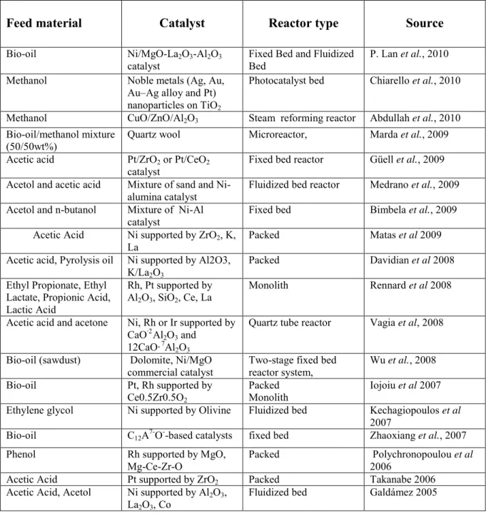
6-3 Composition and structure of soot ... 49
6-4 Soot gasification ... 51
REFERENCES ... 52
CHAPTER 3: MATERIALS AND METHODS
... 61
1- HORIZONTAL TUBULAR REACTOR ... 61
2- ENTRAINED FLOW REACTOR ... 64
a- Steam generator ... 66
b- Gas flow preheater ... 67
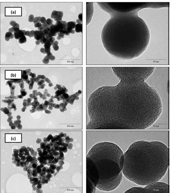
c- Dosing and injection of oil ... 68
d- Sampling device ... 71
e- Determination of gas residence time ... 72
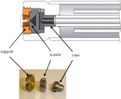
3- SOOT QUANTIFICATION DEVICE ... 74
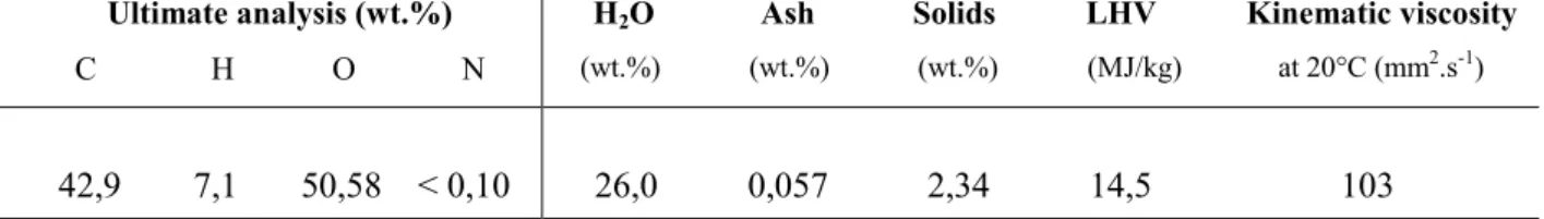
4- FEEDSTOCK ... 79
5- BIO-OIL CHARACTERIZATION BY TG-DSC ... 79
a- Under nitrogen ... 80
b- Under air ... 81
REFERENCES ... 83
CHAPTER 4: WOOD BIO-OIL PYROLYSIS: INFLUENCE OF
TEMPERATURE, HEATING RATE AND ASH CONTENT ON CHAR, GAS
AND TAR YIELD
... 85
ABSTRACT ... 85
1- INTRODUCTION ... 86
2- MATERIALS AND METHODS ... 90
2-1 Description of the laboratory device and of the procedure ... 90
2-1-1 Horizontal Tubular Reactor HTR ... 90
2-1-2 Entrained Flow Reactor EFR ... 91
2-2 Feedstock ... 93
iii
3- RESULTS AND DISCUSSIONS ... 95
3-1 Preliminary runs of bio-oil pyrolysis at two final reactor temperature ... 95
3-2 Effect of heating rate and final temperature on the product yields ... 97
3-3 Effect of ash content ... 102
4- CONCLUSIONS ... 105
REFERENCES ... 106
CHAPTER 5: WOOD BIO-OIL NON CATALYTIC GASIFICATION:
INFLUENCE OF TEMPERATURE, DILUTION BY AN ALCOHOL AND ASH
CONTENT ... 109
ABSTRACT ... 109
1- INTRODUCTION ... 110
1-1 Steam reforming of bio-oil ... 112
2- MATERIALS AND METHODS ... 114
2-1 Description of experimental device ... 114
2-2 Feedstock ... 116
3- RESULTS AND DISCUSSIONS ... 116
3-1 Effect of temperature ... 116
3-2 Equilibrium calculation ... 118
3-3 Effect of dilution by a solvent ... 120
3-4 Effect of ash ... 121
4- CONCLUSIONS ... 123
REFERENCES ... 124
CHAPTER 6: SOOT FORMATION AND OXIDATION DURING BIO-OIL
GASIFICATION: EXPERIMENTS AND MODELING
... 127
ABSTRACT ... 127
1- INTRODUCTION ... 128
2- MATERIALS AND METHODS ... 132
2-1 Description of experimental device ... 132
2-2 Soot quantification device ... 134
2-3 Feedstock ... 138
2-4 Model description and parameter setting... 138
2-5 Experimental conditions ... 142
3- RESULTS AND DISCUSSIONS ... 142
3-1 Profiles of product gas ... 142
iv
3-1-2 CO and CO2 production ... 146
3-1-3 Light hydrocarbon gas production ... 146
3-2 Soot production ... 147
3-3 Discussion: contribution of the model ... 150
a- Pyrolysis situation ... 150
b- Gasification situation ... 151
c- Partial oxidation situation ... 153
4- CONCLUSIONS ... 156
REFERENCES ... 157
GENERAL CONCLUSION
... 161
Perspectives ... 163
v
ABBREVIATIONS
AD Anaerobic Digestion
BCO Bio Crude Oil
BDO Biomass-Derived Oil
BFB Bubbling Fluidized Bed
CIRAD Centre de coopération Internationale en
Recherche Agronomique pour le Développement
CFB Circulating Fluidized Bed
EC Extinction Coefficient
EU European Union
FTIR Fourier Transform InfraRed
GaSPar Gasification of Solid Particles
GHG Greenhouse Gas
HACA H2 abstraction, C2H2 addition
HHV High Heating Value
HTR Horizontal Tubular Reactor
HTU Hydrothermal Upgrading
HT-EFR High Temperature Entrained Flow Reactor
IC Internal Combustion
ICP-OES Inductively Coupled Plasma Optical Emission
Spectrometry
IEA International Energy Agency
LHV Low Heating Value
MHV Medium Heating Value
NA Not Available
NDIR Non-Dispersive InfraRed
NPOX Non-Catalytic Partial Oxidation
NREL Renewable Energy Laboratory
O/C Oxygen to Carbon
ODE Ordinary Differential Equations
OSR Oxidative steam reforming
PAH Polycyclic Aromatic Hydrocarbon
POX Partial oxidation
ppb parts per billion
RAPSODEE Research in Albi on Particulate Solids, Energy and the Environment
S/C Steam to Carbon
S/F Steam to Fuel
SNG Synthetic Natural Gas
SR Steam reforming
SWBR Softwood Bark Residues
TCD Thermal Conductivity Detector
TEM Transmission Electron Microscopy
TGA Thermogravimetric Analysis
TGA-DSC Thermogravimetry-Differential
Scanning Calorimeter
1
CHAPTER 1: INTRODUCTION
1- Research Motivation
Energy and environmental issues are two common concerns of modern society. Energy is a central part of every human being‘s daily life. In all its forms, such as chemical energy (food), thermal energy (heat), or electricity, energy has the ability to transform the daily lives of humans across the world by easing workloads, boosting economies and generally increasing the comfort of our lives. Worldwide energy consumption has been increasing rapidly. This has been accelerated by the improvement of the quality of life that almost directly relates to the amount of energy consumed. At present, fossil fuels based energy resources, such as coal, gas, and oil supply the majority of the total world energy requirement. According to the statistical data from the International Energy Agency (IEA), total world energy consumption without any structural intervention is expected to grow constantly in the next decades (Figure 1).
Energy needs are mainly met by the combustion of fossil fuels: their incidence is nowadays 81% in terms of total primary energy (Figure 2) and 67% for electricity production [EIA 09].
2
Figure 2. World primary energy consumption by fuel (adapted from [EIA 09])
The global warming owing to the emissions of greenhouse gas is the most drastic consequence of the use of fossil fuels. According to experts in the field, global warming can disturb the natural equilibrium of the Earth‘s ecosystem. If CO2 emissions are not regulated,
global warming can have severe consequences for environment. These consequences, although some of them are not fully corroborated, are increasing sea and ocean levels, ocean acidification, change in rainfall patterns, hurricanes, volcanic eruptions, earthquakes and plant or animal extinctions, among others. Hence, new conversion technology should address this increasing concern. Therefore, the reduction of energy-related CO2 emissions is the industrial
societies greatest challenge at the beginning of the 21st century. A reduction of at least 1% per year is postulated to be necessary. However, with the present use of energy fuels, a steady annual increase of 2% is expected if there will not be a major change in energy and climate policies [Jochem 00].
There are several strategies in order to fight the consequences from the use of fossil fuels as major primary energy sources. Besides strategies for energy saving, i.e. a reduction of the energy consumption and an increase of the exergy of an energy carrier, the use of renewable energy sources is the most logical solution for the energy problem. According to the World Energy Outlook[EIA 00], waste and renewable like (direct) solar, wind, tide, wave energy and biomass are expected to be the fastest growing primary energy sources, with an annual growth rate averaging 2.8% over the outlook period.
3
Among the renewable sources of energy, substantial focus of research is currently on the use of biomass. Besides being a renewable source of energy, there are many other advantages associated to the use of biomass. It is available abundantly in the world. Its use does not increase the net amount of CO2 in the atmosphere. Indeed the CO2 released from processing biomass originally came from the atmosphere itself, and was captured by the vegetation during the photosynthesis process, so that by thermally processing biomass, we are simply promoting the CO2 cycle at short time scale.
2- Background
Biomass gasification is a promising technology, which can contribute to develop future energy systems which are efficient and environmentally friendly in order to increase the share of renewable energy for heating, electricity, transport fuels and higher applications.
The process of gasification to produce combustible gas also known as syngas or producer gas from organic feeds was used in blast furnaces over 180 years ago. The possibility of using this gas for heating and power generation was soon realized and then emerged in Europe producer gas systems, which used charcoal and peat as feed material. At the turn of the century petroleum gained wider use as a fuel, but during both world wars and particularly World War II, shortage in petroleum supplies led to widespread re-introduction of gasification. By 1945 the gas was being used to power trucks, buses and agricultural and industrial machines. It is estimated that there were close to 9000,000 vehicles running on producer gas all over the world [Breag 79].
After World War II the lack of strategic impetus and the availability of cheap fossil fuels led to general decline in the producer gas industry. However Sweden continued to work on producer gas technology. A decision was then made to include gasifiers in Swedish strategic emergency plans.
The contemporary interest in small scale gasifier R&D, for most part dates from 1973 oil crisis.
The gasification of carbon-containing materials to produce combustible gas is an established technology. Biomass gasification is a thermochemical process that produces relatively clean and combustible gas through pyrolytic and reforming reactions. The syngas generated can be an important resource suitable for direct combustion, application in prime movers such as
4
engines and turbines, or for the production of synthetic natural gas (SNG) and transportation fuels e.g. Fischer-Tropsch diesel.
For energy production, the major concerns about syngas are its heating value, composition, and possible contamination [Wei 05]. The proportion of the combustible gas hydrogen (H2),
methane (CH4), carbon monoxide (CO), and moisture determines the heating value of the gas.
The composition of syngas depends on the biomass properties and gasifier operating conditions. For a specific gasification system, operating conditions play a vital role in all aspects of biomass gasification. These include carbon conversion, syngas composition, tars and soot formation and oxidation [Devi 03].
The main hurdles for large-scale implementation of energy production from solid biomass are the nature of biomass - non uniform, low-energy density, sometimes large ash content - together with the usual inconsistency between the local availability of biomass and the demand for biomass related products: heat, electricity, fuels and chemicals. Usually, import/transport of fossil fuels is cheaper.
Pyrolysis may be a process to overcome these hurdles: biomass is transformed into a versatile liquid called bio-oil, easy to handle and to transport. This bio-oil would then be transported to centralized air/steam gasification units. Bio-oil is an intermediate product which is produced from relatively dry biomass via fast pyrolysis process. It is a liquid with similar elemental composition to its original feedstock and with high bulk and energy density.
The high bulk and energy density of bio-oil can reduce transportation costs to large scale centralized gasification plants; these costs have been a detrimental factor in large scale use of solid biomass resource. Bio-oil can be produced where the biomass is available and then be transported over long distances to central processing units of similar scales as the current petrochemical industry. Besides technical and logistic advantages, this conversion chain may also give incentives for economic development and job creation especially in rural areas. At the industrial level, one of the major issues in biomass gasification is the soot formed during the process which influences syngas purity. Soot are solid particles that also clog engine parts and thus affect the ability of engines to run smoothly and have also serious environmental effects.
5
3- Objectives
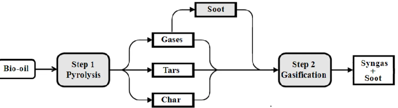
The chemistry of bio-oil gasification is very complex. Biomass gasification proceeds via a two-step process, pyrolysis followed by gasification that includes gas and tars reforming plus char and soot conversion, as illustrated in Figure 3. Pyrolysis is the decomposition of the bio-oil by heat. This step, also known as devolatilization, is endothermic and produces mainly volatile materials in the form of gaseous and condensable hydrocarbons called tars. The remaining nonvolatile material, containing mainly the carbon material, is referred to as char. The volatile hydrocarbons and char are subsequently converted to syngas in the presence of steam in the second step called gasification.
The overall purpose of this research is to investigate the feasibility of a whole bio-oil non catalytic steam gasification process for the production of high quality syngas.
The objectives of this work are as follows:
To better understand the first step of gasification i.e. pyrolysis, and investigate the effect of operating conditions, in particularly the influence of temperature and heat flux density on the pyrolysis products yield;
Thereafter, to study the whole process (pyrolysis+gasification), and to determine the syngas yield and its composition versus operating conditions notably temperature.
Figure 3. Scheme of the non catalytic gasification of wood bio-oil
In addition of pyrolysis of bio-oil product (gases, tars and char), the process may lead to emissions of soot (solid carbonaceous material). In this thesis we are also interested in the soot formation and oxidation behavior. This research all together is expected to produce a reliable model to support the design of future large scale plants for non catalytic gasification of bio-oil.
6
4- Scope of the Thesis
This introduction is considered as Chapter 1.
Chapter 2 gives an overview based on literature review of biomass sources, physical and chemical characteristics of lignocellulosic biomass, biomass conversion, gasifier types, bio-oil characteristics and applications and finally a review of literature on soot formation and oxidation during thermochemical conversion of biomass.
Chapter 3 describes in details the different experimental set-ups that were developed and used. Protocols are explained for the bio-oil pyrolysis, gasification and partial oxidation experiments that were carried on. Details are also given about the developed bio-oil pulverization feeder and the soot quantification device.
Chapters 4, 5 and 6 are the core of the thesis. They contain the results obtained from experimental and modeling work in the form of three journal papers. One of the papers have already been accepted and published; others have been submitted and are being reviewed. The objective of Chapter 4 is to characterise the pyrolysis step of bio-oil. In particular, it will focus on the influence of the heating rate and the final pyrolysis temperature on the products distribution. Two complementary devices, namely: a Horizontal Tubular Reactor (HTR) and a High Temperature - Entrained Flow Reactor (HT-EFR), were used to study a wide range of heating rates, representative of slow and flash pyrolysis, in the range from 2 to 2000°C.s-1 and
final temperature from 550 to 1000°C. Finally the catalytic effect of ash on the bio-oil pyrolysis process has also been studied.
Chapter 5 is focused on the non catalytic steam gasification in the absence of O2 of whole
bio-oil in the HT-EFR. The objectives of this work are to determine the syngas yield and composition versus temperature over a wide range from 1000°C to 1400°C. In parallel a thermodynamic equilibrium calculation is performed in order to determine the theoretical temperature at which the thermodynamic equilibrium is reached. Finally the influence of ash on the gasification process has also been studied.
Chapter 6 relates a study on soot formation and oxidation during bio-oil thermal conversion in the HT-EFR. A model is proposed to describe soot formation and oxidation. It is based on the description of bio-oil heating, devolatilization, reforming of gases and gasification of solids (char and soot). To support the model validation, experiments were carried out. The temperature was varied from 1000 to 1400°C. Three thermochemical situations were studied in order to cover possible industrial applications: default of steam, large excess of steam (H2O/C = 8), and in the presence of oxygen in the range O/C = 0.075 to 0.5.
7 REFERENCES
[Breag 79] Breag GR, Chittenden AE. Producer Gas; Its Potential and Applications in Developing countries, Report No. G130, Tropical Products Institute, London, October 1979. [Devi 03] Devi L, Ptasinski KJ, Janssen FJ.JG. A Review of the Primary Measures for Tar Elimination in Biomass Gasification Processes 2003;24:125-140.
[EIA 09] IEA (International Energy Agency), Key World Energy Statistics, Paris, France, 2009.
[EIA 08] IEA (International Energy Agency), World Energy Outlook, Paris, France, 2008. [EIA 00] IEA (International Energy Agency), World Energy Outlook 2000 www.IEA.org. [Jochem 00] Jochem E. Goldemberg J. Challenges and options for future energy policy. Bulletin - Magazine of the Swiss Federal Institute of Technology in Zurich 2000.
[Wei 05] Wei L. Experimental study on the effects of operational parameters of a downdraft gasifier. PhD Thesis, Mississippi State, USA 2005.
9
CHAPTER 2: LITERATURE REVIEW
In this chapter, a general overview is given of biomass, energy generation processes from biomass, gasifier types, bio-oil characteristics and applications. A literature review is also provided on soot formation and oxidation during themochemical conversion of biomass.
1- BIOMASS
1-1 Definition
The sun provides the majority of energy on earth through solar radiation. Solar energy is a result of nuclear fusion reactions within the sun and this energy radiates to the earth over a range of wavelengths of electromagnetic energy that we know as light and heat. This light energy is naturally harnessed by plants through photosynthesis to create a source of energy in the form of complex carbon, hydrogen, and oxygen.
The word ―biomass‖ consists of ―bio‖ + ‖mass‖ and originally refers in the field of ecology to amount of animals and plants.
The term biomass is defined as any organic matter that is available on a renewable basis, including dedicated energy crops and trees, agricultural food and feed crop residues, aquatic plants, wood and wood residues, animal wastes and other waste materials [Kamm 06]. Lignocellulose is the most abundant renewable biomass. It is constituted of cellulose, hemicelluloses and lignin, as well as other minor components. Both cellulose and hemicelluloses fractions are polymers of sugars.
1-2 Physical and chemical characteristics of lignocellulosic biomass 1-2-1 Composition
Understanding the chemical structure of biomass is extremely important for the development of processes of production of fuels and chemicals from biomass. Biomass has a complex chemical composition, and both organic and inorganic constituents are important for further handling and conversion processes.
The term "lignocellulosic biomass" is used when referring to plants, softwood or hardwood. Figure 1 shows the complete molecular structure of lignocellulosic biomass.
10
Figure 1. Complete molecular structure of biomass containing the three main components cellulose is shown in orange, hemicelluloses in blue, and lignin in green [Ceres Biofuels 07]
- Cellulose is a major structural component of cell walls, and it provides mechanical strength and chemical stability to plants. Solar energy is absorbed through the process of photosynthesis and stored in the form of cellulose [Raven 92]. It has been estimated that around 7.5x10¹⁰ tonnes of cellulose are consumed and regenerated every year
[Kirk-Otmer 01]. It is thereby the most abundant organic compound in the world. Cellulose is a linear crystalline polysaccharide, with general formula (C6H10O5)n. It
serves as the framework substance, making up 40-50% of wood. The polymer is formed from repeating units of cellobiose, a disaccharide of β-linked glucose.
- Hemicelluloses are matrix substances between cellulose microfibrils. They are polysaccharides of variable composition containing both five (including xylose and arabinose) and six carbon monosaccharide units (including galactose, glucose, and mannose). Hemicelluloses constitute 20 to 30% of wood and other biomasses, generally with higher concentrations in hardwoods than softwoods. The most abundant monomeric unit of hemicelluloses is xylan.
- Lignin is a polymer constituted of aromatic compounds produced through a biosynthetic process and forms a protective layer for the plant walls. The lignin is formed of highly branched, substituted, mononuclear polymers of phenylpropane units, derived from coniferyl, sinapyl, and p-coumaryl alcohols. It is often bounding to adjacent cellulose fibers to form a lignocellulosic complex. The structure varies among different plants. Softwood lignin is mainly composed of guaiacyl units
11
stemming from the precursor trans-coniferyl alcohol. Hardwood lignin is mostly composed of guaiacyl and syringyl units derived from coniferyl and trans-sinapyl alcohols. Grass lignin contains p-hydroxyphenyl units deriving from trans-coumaryl alcohol. Almost all plants contain all three guaiacyl, syringyl, and p-hydroxyphenyl units in lignin.
Apart from the three basic chemical compounds, water is also present in the complex forming biomass. Furthermore, minor amounts of proteins, minerals and other components can be found in the lignocellulose composition as well.
The composition of lignocellulose highly depends on its source. There is a significant variation of the lignin and (hemi) cellulose content in lignocellulose depending on whether it is derived from hardwood, softwood, or grass. Table 1 summarizes the composition of lignocellulose encountered in the most common sources of biomass.
Table 1. Composition of lignocellulose in several sources on dry basis [Sun 02] Lignocellulosic materials Cellulose (%) Hemicelluloses
(%) Lignin (%) Hardwoods stems 40–55 24–40 18–25 Softwood stems 45–50 25–35 25–35 Nut shells 25–30 25–30 30–40 Corn cobs 45 35 15 Grasses 25–40 35–50 10–30 Paper 85–99 0 0–15 Wheat straw 30 50 15 Sorted refuse 60 20 20 Leaves 15–20 80–85 0
Cotton seed hairs 80–95 5–20 0
Newspaper 40–55 25–40 18–30
Waste papers from
chemical pulps 60–70 10–20 5–10
Primary wastewater solids 8–15 NA 24–29
Swine waste 6.0 28 NA
Solid cattle manure 1.6–4.7 1.4–3.3 2.7–5.7
Coastal Bermuda grass 25 35.7 6.4
12 1-2-2 Internal structure – physical properties
Lignocellulosic biomass has a complex internal structure. It is formed of a number of major components that have, in their turn, also complex structures. To obtain a clear picture of the material, a more detailed analysis of the structure of each main component is made in this section, as well as a description of the structure of lignocellulose itself. The physical properties of each of the components are also addressed, and how each of these components contributes to the behaviour of the complex structure as a whole.
a- Cellulose
Cellulose is a high molecular-weight (106 g or more) linear polymer of
β-(1→4)-D-glucopyranose units in the 4C
1 conformation. The fully equatorial conformation of β-linked
glucopyranose residues stabilizes the chair structure, minimizing flexibility. Glucose anhydride, which is formed via the removal of water from each glucose unit, is polymerized into long cellulose chains. The basic repeating unit of the cellulose polymer consists of two glucose anhydride units, which form a cellobiose unit.
The chemical formula of cellulose is (C6H10O5)n and the structure of one chain of the polymer
is shown in Figure 2.
Figure 2. Structure of cellulose molecule
Many properties of cellulose depend on its degree of polymerization (DP), i.e. the number of glucose units that make up one polymer molecule. The DP of cellulose can extend to a value of 17,000, even though more commonly a number of 800-10,000 units is encountered [Kirk-Otmer 01].
The nature of the bond between the glucose molecules (β-1,4 glucosidic) allows the polymer to be arranged in long straight chains. The latter arrangement of the molecule, together with the fact that the hydroxides are evenly distributed on both sides of the monomers, allows the formation of hydrogen bonds between the molecules of cellulose. The hydrogen bonds result in the formation of a compound that is constituted of several parallel chains which are attached to each other [Faulon 94].
13
An illustration of the arrangement of the cellulose molecules in parallel chains and of the accompanying hydrogen bonding is given in Figure 3.
Figure 3. Illustration of the arrangement of the cellulose molecules in parallel chains and of the accompanying hydrogen bonding
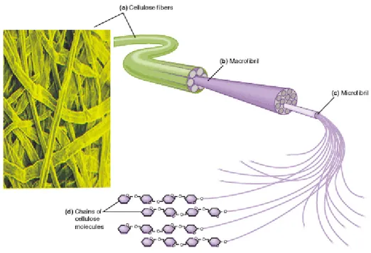
Cellulose is found both in crystalline and non-crystalline structure. The coalescence of several polymer chains leads to the formation of microfibrils, which in turn are united to form fibres. In this way cellulose can obtain a crystalline structure. Figure 4 illustrates structure as well as placement of cellulose in the cell wall.
Figure 4. Formation of micro- and macrofibrils (fibres) of cellulose and their position in the wall
14
Cellulose degradation occurs at 240-350°C to produce anhydrocellulose and levoglucosan. When cellulose is pyrolyzed at a heating rate of 12°C/min under helium gas, endothermic reaction is observed at 335°C (temperature of maximum weight loss). The reaction is completed at 360°C [Mohan 06].
b- Hemicelluloses
Hemicelluloses are a mixture of various polymerized monosaccharides such as glucose, mannose, galactose, xylose, arabinose, 4-O-methyl glucuronic acid and galacturonic acid residues. Hemicelluloses extracted from plants have a high degree of polydispersity, polydiversity and polymolecularity (a broad range of size, shape and mass characteristics). Hemicelluloses exhibit lower molecular weights than cellulose. The number of repeating saccharide monomers is only ∼150, compared to the number in cellulose ∼800-10,000.
Figure 5 shows the molecule of xylan, which is the main component of hemicelluloses. It is based on 1-4 linkages of xylopyranosyl units with α-(4-O)-methyl-D-glucuronopyranosyl units attached to anhydroxylose units. The result is a branched polymer chain that is mainly composed of five carbon sugar monomers, xylose, and to a lesser extent six carbon sugar monomers such as glucose.
Important aspects of the structure and composition of hemicelluloses are the lack of crystalline structure, mainly due to the highly branched structure, and the presence of acetyl groups connected to the polymer chain [Kirk-Otmer 01].
Figure 5. A schematic representation of the hemicelluloses backbone of arborescent plants The onset of hemicelluloses thermal decomposition occurs at low temperatures. The mass loss of hemicelluloses occur in slow pyrolysis of wood in the temperature range of 130-194°C, with most of this loss occurring above 180°C. However, the relevance of this more rapid
15
decomposition of hemicelluloses versus cellulose does not appear to be relevant during fast pyrolysis, which is completed in a few seconds at a rapid heating rate [Runkel 51].
c- Lignin
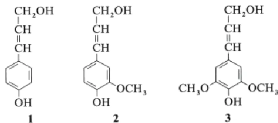
Lignin is the most abundant polymeric aromatic organic substance in the plants. It is an amorphous three-dimensional polymer with phenylpropane units as predominant building blocks. P-coumaryl alcohol, coniferyl alcohol and sinapyl alcohol units (Figure 6) are the most commonly encountered units.
Figure 6. P-coumaryl- , coniferyl- and sinapyl alcohol: dominant building blocks of the three-dimensional polymer lignin
The property of polydispersity, just as with hemicelluloses, characterizes lignin as well. Different branching and bonding in similar molecules are encountered [Lin 02]. Figure 7 shows a model structure of softwood lignin.
Lignin in wood behaves as an insoluble three-dimensional network. It plays an important role in the cell endurance and development, as it affects the transport of water, nutrients and metabolites in the plant cell. It acts as binder between cells and creates a composite material that has a remarkable resistance to impact, compression and bending.
Lignin decomposes when heated at 280-500 ºC. Lignin pyrolysis produces more residual char than does the pyrolysis of cellulose [Mohan 06].
16
Figure 7. A model of chemical structure of softwood lignin [Northey 98]
d- Water
The amount of water in biomass, that is its moisture content, significantly varies from one feedstock to another and may vary between different samples of the same feedstock. Values ranging between 5 and 50% are classically encountered. Moisture content depends on the location of the raw biological material, its surroundings and the season of harvesting. High moisture in feedstock is undesirable for process so that biomass generally passes trhough a stage of drying before conversion.
e- Ash and other components
Ash is the name given to the non-aqueous residual components of biomass that remain after it is burnt. It mainly consists of metal oxides or salts, with 25-45% of the ash being composed of calcium carbonate. The ash component of biomass is non-reactive and cannot be converted into biofuels. Mass fraction of 0.1 to 10% is classically encountered.
Extractives are constituted of the compounds that may be extracted by solvent. They are not integral part of the cellular structure and can be either simple fats, amino acids, chlorophyll or
17
tannin for instance. The type and quantity of extractives found in a given feedstock vary widely from one sample to another [Fengel 89].
1-2-3 Chemical interaction between components
There are four main types of bonds identified in the lignocellulose complex. Those are ether type of bonds, ester bonds, carbon-to-carbon bonds and hydrogen bonds. These four bonds are the main types of bonds that provide linkages within the individual components of lignocellulose (intrapolymer linkages), and connect the different components to form the complex (interpolymer linkages). The position and bonding function of the latter linkages is summarized in Table 2 [Faulon 94].
Table 2. Overview of linkages between the monomer units that form the individual polymers lignin, cellulose and hemicelluloses, and between the polymers to form lignocelluloses Bonds within different components (intrapolymer linkages)
Ether bond Lignin, (hemi)cellulose Carbon to carbon Lignin
Hydrogen bond Cellulose Ester bond Hemicelluloses Bonds connecting different components (interpolymer linkages) Ether bond Cellulose-Lignin Hemicelluloses lignin Ester bond Hemicelluloses-lignin Hydrogen bond Cellulose-hemicelluloses Hemicelluloses-Lignin Cellulose-Lignin
a- Intrapolymer linkages
The main types of bonds that connect the building molecules within the lignin polymer are ether bonds and carbon-to-carbon bonds (Table 2). Ether bonds may appear between allylic and aryl carbon atoms, or between aryl and aryl carbon atoms, or even between two allylic carbon atoms. The total fraction of ether type bonds in the lignin molecule is around 70% of the total bonds between the monomer units. The carbon-to-carbon linkages form the remaining 30% of the total bonds between the units. They can also appear between two aryl carbon atoms or two allylic carbon atoms, or between one aryl and one allylic carbon atom [5 Kirk-Otmer 01].
18
The polymer of cellulose is formed on the basis of two main linkages:
- The glucosidic linkage is the one that forms the initial polymer chain. More specifically, it is a 1-4 β D-glucosidic bond that connects the glucose units together. The glucosidic bond can also be considered as an ether bond, since it is in fact the connection of two carbon atoms with an elementary oxygen interfering [Solomon 88].
- The hydrogen bond is considered to be responsible of the crystalline fibrous structure of cellulose. The arrangement of the polymer in long straight parallel chains together with the fact that the hydroxyl groups are evenly distributed in both sides of the glucose monomer, allow the formation of hydrogen bond between two hydroxyl groups of different polymer chains [Faulon 94].
It has been identified that carboxyl groups are also present in cellulose in a fraction of 1 carboxyl per 100 or 1,000 monomer units of glucose [Krassig 02].
As already mentioned, hemicelluloses consist of polysaccharides other than cellulose. Their structure (Figure 2) reveals that ether type of bonds, such as the fructosic and glucosidic bonds, is the main type of bonds in these molecules. The main difference with cellulose is that the hydrogen bonds are absent and that there is significant amount of carboxyl groups. The carboxyl groups can be present as carboxyl or as esters or even as salts in the molecule [Kirk-Otmer 01].
b- Interpolymer linkages
In order to determine the linkages that connect the different polymers of the lignocellulose complex, lignocellulose is broken down and the individual components are separated. However, their separation is commonly achieved by methods that result in alteration of their original structure. As a consequence, the conclusions on the connecting linkages between the polymers remain questionable.
However, it has been identified that there are hydrogen bonds connecting lignin with cellulose and with hemicelluloses, respectively. Furthermore, the existence of covalent bonds between lignin and polysaccharides is identified. More specifically, it is certain that hemicelluloses connect to lignin via ester bonds. It is also known that there are ether bonds between lignin and the polysaccharides. It is still not clear though whether the ether bonds are formed between lignin and cellulose, or hemicelluloses.
Hydrogen bonding between hemicelluloses and cellulose is also identified. However, this linkage is not expected to be strong due to the fact that hemicelluloses lack of primary alcohol functional group external to the pyranoside ring [Faulon 94].
19
2- LIGNOCELLULOSIC BIOMASS RESOURCES
Up to the 19th century, biomass in the form of firewood and charcoal was the main source of energy, but then it was replaced by coal and oil in the 20th century. In the 21st century,
however, there is interest on biomass again because of the following characteristics: it is renewable, it is storable and substitutive, it is abundant worldwide, and it is carbon neutral. There is no established way of classification of biomass, which is defined differently according to the field; categorization depends on the purpose and application. Generally there are two ways to categorize biomass: one is biological categorization based on types of existing biomass in nature (such as categorization according to ecology or type of vegetation), and the other is based on the use or application as feedstock. The latter is highly significant in terms of making effective use of energy sources.
Biomass can be found in various forms, each of which has specific properties, uses and advantages. The main sources of lignocellulosic biomass are wood from conventional and short-rotation forestry, other energy crops, residues from forestry and agricultural production, and by-products and wastes from industrial and municipal processes.
An example of biomass categorization appears in Table 3. In this categorization, biomass includes not only the conventional products and wastes from agriculture, forestry, and fisheries, but also plantation biomass.
20
Table 3. Examples of biomass resources Category Examples
Dedicated plantations Short-rotation forestry (eucalyptus willow) Perennial crops (miscanthus)
Arable crops (rapeseed, sugarcane, sugarbeet) Residues Wood from forestry thinning
Wood felling residues Straw from cereals
Other residues from food and industrial crops (sugarcane, tea, coffee, rubber trees, oil and
coconut palms) By-products and wastes Sawmill waste Manure
Sewage sludge
Organic fraction of municipal waste Used vegetable oils and fats
3- BIOMASS CONVERSION
Although it is a common source of energy (especially in developing countries), biomass is not an ―ideal‖ fuel due to its fibrous nature, low density and low heating value. Indeed, the energy that can be obtained from a particular resource depends on its chemical composition and moisture content. Except when straightforward combustion is appropriate, it is not usually possible to directly use biomass raw materials. Therefore biomass is treated in various processes to create products which can be more efficiently and economically be used in modern energy equipments. This conversion is generally achieved by some type of biological or thermal processes as shown in Figure 8.
Fermentation and digestion are examples of biological processes. They use microbial or enzymatic activity to convert sugars from biomass into ethanol, or biomass into solid fuels or biogas.
Combustion, gasification and pyrolysis are examples of thermal processes. We are focused on this type of process in this research work and will therefore describe them in more detail in the following sections. They produce either direct heat or gas or bio-oil. The gas can be used
21
to drive a motor or a fuel cell or be converted into liquid or gaseous fuels. The bio-oil can be further transformed into gaseous and upgraded liquid fuels.
Figure 8. Main conversion options for biomass to secondary energy carriers [Turkenburg00]
3-1 Pyrolysis
Pyrolysis is the thermal degradation at temperatures of 300-600°C of carbonaceous material in the absence of an externally supplied oxidizing agent. The products of pyrolysis are char (solid), tar (liquid at room temperature, therefore often referred to as ―bio-oil‖ in the context of this process) and gas. The relative yields of the products depend very much on the process conditions, i.e. heating rate, final temperature, pressure and gas residence time in the reactor. The heating rate of the biomass particles is the most important parameter for pyrolysis with regard to the product yield distribution. Slow pyrolysis (heating rates in the order of 10°C.s-1) is applied for maximum char yields, fast or even flash pyrolysis (heating rates up to 104° C.s-1 provide maximum yields of bio-oil.
22 3-2 Gasification
Gasification is the thermal degradation of carbonaceous material in the presence of an externally supplied oxidizing agent: air, carbon dioxide or steam. The main product of gasification is a mixture of gas mainly constituted of carbon monoxide, hydrogen, carbon dioxide, water, methane, air and nitrogen. The gas may also contain solid particles (ash, soot), oxygenated organics and higher-molecular hydrocarbons, the latter two product classes are commonly referred to as ―tars‖. The quality of the producer gas depends on the same parameters as in the pyrolysis process.
The main purpose of biomass gasification is the production of low or medium heating value (LHV, MHV) gas which can be used as fuel gas in an internal combustion (IC) engine for power production. Gas turbines, fuel cells, the synthesis of liquid fuels or syngas are other applications of the producer gas. Gasification is the process of interest in this work.
3-3 Combustion
Combustion is the complete oxidation of the biomass feedstock. Contrary to pyrolysis and gasification, which are fuel conversion processes, combustion can provide collectible energy (heat). The hot flue gas is used for heating purposes or for steam production by means of subsequent steam turbine processes. Moreover, the Stirling engine provides a possibility for power production by combustion without steam production. Low NOx processes and particle and aerosol reduction are important subjects of the current biomass combustion research.
3-4 Liquefaction
Liquefaction is the thermochemical conversion of biomass in the liquid phase at low temperatures (250-350°C) and high pressures (100-200 bar), usually with a high hydrogen partial pressure and catalysts to enhance the rate of reaction and/or to improve the selectivity of the process. The main goal is to reach maximum liquid-yields with higher quality than from the pyrolysis process, i.e. the produced fuel has a higher heating value and lower oxygen content. The lower oxygen content makes the fuel chemically more stable and requires less upgrading to hydrocarbon product.
23
4- PYROLYSIS AND GASIFICATION: LITERATURE REVIEW
4-1 Pyrolysis
As previously said, pyrolysis is a thermal decomposition process that takes place in the absence of oxygen to convert biomass into solid charcoal, liquid (bio-oil), and gas. Pyrolysis is considered to be an industrial realized process for biomass conversion [IEA 2006] [Maschio 92] [Marsh 07] [Demirbas 01].
As mentioned before, each component of lignocellulosic biomass is pyrolysed at different rates by different mechanisms and pathways. Lignin decomposes over a wider temperature range compared to cellulose and hemicelluloses which rapidly degrade over narrower temperature ranges. Hence there is an apparent thermal stability of lignin during pyrolysis. Thermogravimetry analysis (TGA) testing of biomass shows that there are three stages for a typical biomass pyrolysis process [Maschio 92]. The first stage, pre-pyrolysis, occurs between 120 and 200°C with a slight weight loss, when some internal rearrangements, such as bond breakage, the appearance of free radicals, and the formation of carbonyl groups take place, with a corresponding release of small amounts of water (H2O), carbon monoxide (CO), and
CO2. The second-stage is the main pyrolysis process, during which solid decomposition
occurs, accompanied by a significant weight loss from the initial biomass. The last stage is the continuous char devolatilization, caused by the further cleavage of C-H and C-O bonds. Depending on the reaction temperature and residence time, pyrolysis can be classified into slow pyrolysis, intermediate pyrolysis fast pyrolysis, and flash pyrolysis.
4-1-1 Intermediate and slow pyrolysis
Slow pyrolysis has been applied for thousands of years and has been mainly used for the production of charcoal. In slow pyrolysis, biomass was typically heated to ~ 500 ºC at slow heating rates (up to 10-20°C/min). The vapor residence time varies from 5 min to 30 min [Mohan 06]. Thus, the components in the vapor phase continue to react with each other, as solid char and liquid are being formed.
The main product, charcoal, can be used in a wide range of areas, from domestic cooking and heating to metallurgical or chemical use as the raw material for production of chemicals, activated carbon, fireworks, absorbents, soil conditioners, and pharmaceuticals [Karaosmanoglu 99]. As reported by Mok et al. [Mok 92], a higher yield of charcoal can be obtained from biomass feedstocks with higher lignin contents and lower hemicelluloses
24
contents. In contrast to fast pyrolysis, slow pyrolysis does not necessarily require fine feedstock particle size (smaller than 1 mm).
4-1-2 Fast pyrolysis
Fast pyrolysis is a process in which very high heat flux are imposed to biomass particles, leading to very high heating rates, in the absence of oxygen. Biomass decomposes to generate vapors, aerosol, and char. After cooling and condensation of the vapors and aerosol, a dark brown mobile liquid is formed which has a heating value of about half of the conventional fuel oil.
Fast pyrolysis process produces 60-75 wt% of liquid bio-oil, 15-25-wt% of solid char, and 10-20-wt% of non condensable gas, depending on the feedstock used. No waste is generated because the bio-oil and solid char can each be used as a fuel and the gas can be recycled back in the process. Fast pyrolysis uses much higher heating rates than slow pyrolysis. While slow pyrolysis is related to the traditional pyrolysis processes for making charcoal, fast pyrolysis is an advanced process which is carefully controlled to give high yields of liquid. Research has shown that maximum liquid yields are obtained with high heating rates, at reaction temperatures around 500°C and with short vapour residence times to minimize secondary reactions.
Very short residence times result in incomplete depolymerization of the lignin due to random bond cleavage and inter-reaction of the lignin macromolecule resulting in a less homogenous liquid product, while longer residence times can cause secondary cracking of the primary products, reducing yield and adversely affecting bio-oil properties [Bridgewater 99].
The essential features of fast pyrolysis process are:
very high heating and heat transfer rates, which usually requires a finely ground biomass feed: <1mm
carefully controlled pyrolysis reaction temperature of around 500°C in the vapour phase, with short vapour residence times of typically less than 2 s;
rapid cooling of the pyrolysis vapours to give the bio-oil product. 4-1-3 Flash pyrolysis
Very fast pyrolysis is sometimes referred to as ‗flash pyrolysis‘ [Demirbas 02], usually in the context of laboratory studies involving rapid movement of substrate through a heated tube under gravity or in a gas flow. Higher temperatures and shorter residence times than fast pyrolysis are used; the main product distributions are similar to fast pyrolysis. The distinction
25
between flash and fast pyrolysis has largely disappeared and now the term ‗flash‘ has largely disappeared and is gradually being replaced by a more generalized definition for fast pyrolysis.
4-1-4 Fast pyrolysis reactor configuration
Fast pyrolysis conversion technology has led to design of original reactor systems that provide the essential ingredients of high heating rates, moderate temperatures and short vapour product residence times for liquids. The most commonly used reactors for fast pyrolysis are bubbling fluidized-bed, circulating fluidized-bed, ablative, entrained flow, rotating cone, and vacuum reactors.There are three main methods achieving fast pyrolysis.
1. Ablative pyrolysis, in which heat is transferred by conduction: wood is pressed against a heated surface and rapidly moved during which the wood melts at the heated surface and leaves an oil film behind which evaporates. This process uses large particles of wood and is typically limited by the rate of heat supply to the reactor. It leads to compact and intensive reactors that do not need a carrier gas, but with the penalties of surface area controlled system and moving parts at high temperature.
2. Bubbling fluidized bed and circulating fluidized bed pyrolysis, in which heat is transferred from a heat source to the biomass by a mixture of convection and radiation. The heat transfer limitation is within the particle, thus, requiring very small particles of typically no more than 3 mm to obtain good liquid yields. Substantial carrier gas is needed for fluidisation or transport.
3. Vacuum pyrolysis, which has slow heating rates but removes pyrolysis products as rapidly as in the previous methods, which thus simulates fast pyrolysis. Larger particles can be accepted but the vacuum leads to larger equipment and higher costs. Total liquid yields are typically lower than 60-65% compared to 75-80 wt% with the previous two methods.
4-1-5 Pyrolysis products
a- Char
Char is a porous carbon structure that remains after the hydrogen and oxygen fractions have left the fuel. Char is often defined as the solid residue after pyrolysis. It is often polluted with other components: mineral fractions and after incomplete pyrolysis, large fractions of hydrogen and oxygen, that can still be present in char.
Char is believed to contribute to the formation of polycyclic aromatic hydrocarbon (PAHs) during biomass pyrolysis, particularly at low temperature [Sharma 04]. Char can be used as a
26
fuel in form of briquettes or as a char-oil, char-water slurry; alternatively char can be upgraded to activated carbon and used in purification processes [Islam 05].
The properties of the char obtained after biomass pyrolysis have a direct influence on the subsequent char oxidation step, since the amount and type of pores determine the gas accessibility to the active surface sites. Properties of char are decisively affected not only by properties of parent material but also by pyrolysis operating conditions, mainly the heating rate, the maximum temperature and the residence time at this temperature.
b- Pyrolysis liquid
The liquid product from biomass pyrolysis is known as bio-oil. Bio-oil is not a product of thermodynamic equilibrium during pyrolysis but, as detailed previously, it is produced with short residence times and rapid cooling or quenching from the pyrolysis temperature. This condensate is not at thermodynamic equilibrium at storage temperatures. Hence the bio-oil chemical composition tends to change toward thermodynamic equilibrium during storage. Details on bio-oil will be given in the following sections.
c- Gas
The third main product from pyrolysis is gas. The gas mainly consists of H2, CO2, CO, and
CH4 together with traces of C2 species. CO2 and CO are preferentially produced at low
temperature, while H2 is released at high temperature.
4-1-6 Pyrolysis reaction schemes
The exact pyrolysis mechanisms of biomass are still not clear, although substantial literature sources are available on biomass devolatilization kinetics and mechanisms. Many biomass devolatilization models have been developed. One-step global mechanisms and semi-global multi-step mechanisms can be basically distinguished. The simplified approaches define devolatilization rates with single or two-step Arrhenius reaction schemes involving pseudo-species.
The one-step global mechanisms can be shown as:
The reaction kinetic rate (k) is expressed in single-step Arrhenius law form as k =A exp(-E a/RT), and the devolatilization rate is expressed as:
(2)
27
where mp is the biomass particle mass, mp,0 is the initial particle mass, and fv,0 is the initial
volatile fraction.
For two-step Arrhenius reaction schemes, the kinetic devolatilization rate expressions of the form proposed by Kobayashi [Kobayashi 76] are:
k1 =A1 exp(-E a/RT) (3)
k2 =A2 exp(-E a/RT) (4)
where k1 and k2 are competing rates that may control the devolatilization over different
temperature ranges.
One-step multi-reaction schemes have been developed by Thunman and Leckner [Thunman 02] via three parallel reactions into char, tar and gas and can be shown as follow:
More recent models are adapted to be able to handle different feedstocks. The composition of the feedstock is represented using three model species. In these models the source species like wood or biomass is replaced by a mixture of cellulose, hemicelluloses and lignin.
Most models are only proposed for cellulose, but several schemes were also proposed for the other biomass main components. The rest of this section describes several other proposed kinetic schemes for cellulose pyrolysis.
Broido and Shavizadeh [Broido 76] developed a multistep model. In this scheme cellulose is firstly converted to an active state by an initiation reaction. Hereafter the active cellulose reacts via two competing reactions to produce tar, char and gas.
The two competing reactions represent two pathways that the decomposition of cellulose can follow. The ―char path‖ is favored at low temperature (200-280°C) whereas the ―tar path‖ dominates at elevated temperatures (280-340°C).
(6) (5)
28
Over the years the validity of the Broido-Shafizadeh model has been disputed by several authors. The use of the initiation step was disputed by Varegyi and Jakab [Varhegyi 94] and by Antal and Varhegyi [Antal 95] who claimed that in most cases experimental data could be better modeled without this step.
A different approach was proposed by Alves [Alves 89 a] [Alves 89 b] and Shrivastava [Srivastava 96]. Their model describes the decomposition by three or two consecutive reactions. This approach requires preset yields for each reaction and therefore lacks of predictive capabilities.
A third approach was the Di Blasi model [Di Blasi 96]. It is similar to the model of Thunman. In this model cellulose decomposes via three competing reactions into gas, char and tar. Consecutively the tar is converted by two secondary reactions into secondary gas and char.
The last model discussed here is the Miller-Bellan model [Miller 97]. This model uses an adapted form of the Broido-Shafizadeh model. It uses three model species to model biomass decomposition and has three sets of kinetic constants for each model component.
(7)
29
It also uses a secondary reaction for the conversion of tar to smaller gas species. In this reaction no difference is made concerning the origin of the tar.
4-1-7 Secondary reactions
Tars produced during the decomposition of the virgin fuel can decompose further. Several authors suggest a transformation of tar to char and gas following two independent reactions. Tar decomposition is suggested to be catalyzed by the solid matrix of the fuel resulting in char creation on the pore walls.
It is unclear however how this takes place. Among several others Miller and Bellan [Miller 97] suggest a single tar reaction with only gas as product species.
4-2 Gasification
4-2-1 Gasification Chemistry
Gasification can be seen as an extension of pyrolysis; biomass gasification is a complex thermo-chemical process involving numerous different reactions. The biomass gasification process can be divided into two parts: pyrolysis and gasification. Pyrolysis was discussed in the previous section. In the gasification part the gas, tar and char react further. Gasification, as a core technology for the production of chemicals and clean power, refers to a process converting biomass into either fuel gas (containing CH4 and some N2 usually) or syngas
(containing mainly H2 and CO).
During gasification several reactions take place. A simplified representation of these reactions is given in equations (12)-(18) [de Jong 03] [Moulijn 01] [Van den 85].
(9)
(10)
30 Heterogeneous reactions C(s) + O2
↔
CO2 (12) C(s) + H2O↔
CO + H2 (13) C(s) + CO2↔
2CO (14) C(s) + 2H2↔
CH4 (15) Homogeneous reactions CO + H2O↔
CO2+ H2 (16) CH4+ H2O↔
CO + 3H2 (17) Cracking reaction Tar aCO + bCH4 + cC (18)Evans and Milne [Evans 87] observed three major reaction regimes during the gasification process identified as primary, secondary, and tertiary regimes as shown in Figure 9.
Biomass is mainly converted into a mixture of hydrogen, carbon monoxide, light hydrocarbons, such as methane, and other non combustible gas such as carbon dioxide, water vapour, and nitrogen. In most cases, the product gas can contain particulates such as char, ash, soot, etc.
Reactor temperature is one of the most important operating conditions which affect both the heating value and producer gas composition.
The gasification process is usually performed with aid of a gasification agent. The gasification agent can be steam, or air, or enriched air, or oxygen, or a combination of steam and an oxygen source, or carbon dioxide. The process is performed at relative high temperature 600- 1500°C. There are also small amounts of impurities in the gas: char, soot, tars, alkalis, nitrogen compounds, sulphur compounds, and chlorine compounds.
The composition of the product gas can vary significantly depending on operating conditions (e.g temperature, operating pressure, oxidant agent), type of feed stock, moisture content in the fuel, mode of bringing the reactants into contact inside the gasifier [Basu 06]. Moreover, the quality of the product gas is associated with other factors such as the type of gasifier, the residence time, and the heating rate which is usually associated with the type of feed stock, particle size and temperature.
![Figure 15. Schematic representation of physical model illustrating bio-oil multiphase structure [Pérez 06]](https://thumb-eu.123doks.com/thumbv2/123doknet/3668351.108552/54.892.202.691.449.880/figure-schematic-representation-physical-illustrating-multiphase-structure-pérez.webp)