To cite this document:
Duplaa, Sébastien and Coutier-Delgosha, Olivier and Dazin,
Antoine and Bois, Gérard and Caignaert, Guy Experimental characterization and
modelling of a cavitating centrifugal pump operating in fast start-up conditions. (2010)
In: 13th International Symposium on Transport Phenomena and Dynamics of Rotating
Machinery - ISROMAC-13, 04 April 2010 - 07 April 2010 (Honolulu-Hawaii, United
States).
O
pen
A
rchive
T
oulouse
A
rchive
O
uverte (
OATAO
)
OATAO is an open access repository that collects the work of Toulouse researchers and
makes it freely available over the web where possible.
This is an author-deposited version published in:
http://oatao.univ-toulouse.fr/
Eprints ID: 9271
Any correspondence concerning this service should be sent to the repository
administrator:
[email protected]
EXPERIMENTAL CHARACTERIZATION AND
MODELLING OF A CAVITATING CENTRIFUGAL PUMP
OPERATING IN FAST START-UP CONDITIONS
*S. Duplaa, O. Coutier-Delgosha, A. Dazin, G. Bois, G. Caignaert
Arts et Métiers ParisTech / LML Laboratory, 8 boulevard Louis XIV, 59046 Lille cedex, France *presently at IRENav, Ecole Navale, Brest, France
[email protected] (+33)298233862
BCRM Brest - Ecole navale et groupe des écoles du Poulmic-IRENav - 29240 Brest cedex 9 France
ABSTRACT
The start-up of rocket engine turbopumps is generally performed only in a few seconds. It implies that these pumps reach their nominal operating conditions after only a few rotations. During these first rotations of the blades, the flow evolution in the pump is governed by transient phenomena, based mainly on the flow rate and rotation speed evolution. These phenomena progres-sively become negligible when the steady behavior is reached. The pump transient behaviour induces significant pressure fluctuations which may result in partial flow vaporization, i.e. cavitation. An existing experimental test rig has been updated in the LML labor-atory (Lille, France) for the start-ups of a centrifugal pump. The study focuses on cavitation induced during the pump start-up. Instantaneous measurement of torque, flow rate, inlet and outlet unsteady pressures, and pump rotation velocity enable to charac-terize the pump behaviour during rapid starting periods. Three different types of fast start-up behaviours have been identified and have been presented at ISROMAC 12 (Duplaa et al, 2008). Ac-cording to the final operating point, the start-up is characterized either by a single drop of the delivery static pressure, by several low-frequency drops, or by a water hammer phenomenon that can be observed both a the inlet and outlet of the pump. A physical analysis to explain these three different types of transient flow behaviour has been recently proposed (Duplaa et al, 2010). In the present paper, a modelling of the fast start ups in cavitating condi-tions is proposed. It consists of a two steps adaptation of fast start-up model in non cavitating conditions proposed by Dazin et al (2007). For that, fast X-rays imaging has been performed in the impeller with the collaboration of the French Atomic Agency (CEA) in order to determinate the high frequency evolution of the volume fraction during fast the start-ups. Although the results of the modelling presented here are not definitive, they are very promis-ing.
NOMENCLATURE
A area (m2)
b height of the blade to blade channels (m) Cu tangential component of the velocity (m/s) Cr = Q / (2prb) radial component of the velocity (m/s)
C torque (Nm)
H Total head (m) L equivalent length (m) Ps static pressure in the pump suction pipe (Pa) Pd static pressure in the pump delivery pipe (Pa) Pvs vapor pressure (Pa)
Q Inlet volume flow rate (m3/s) r impeller radius (m) S limit of the fluid volume in the channels (m2)
t time (s)
u tip velocity =w ´ r2 (m/s)
v inlet pipe velocity (m/s)
V Volume (m3)
b relative flow angle (-) b Volume fraction = Vvap/Vw (-)
DP pump static pressure rise (Pa) d flow rate coefficient : = Q / u2r2
2
(-) f flow rate coefficient = Q / 2pr2b2u2 (-)
Y pressure coefficient = DP / ru2 2 (-) w rotation speed (s-1) ws specific speed = wQ 1/2 / (gH)3/4 (-) t = (Ps + ½rv2 – Pvs)/(½ ru22) (-) r density (kg/m3) Subscripts : 1 impeller inlet 2 impeller outlet cav cavitating conditions d diffuser
f final (steady part of the fast start up) n nominal st steady tr transient v volute w Liquid water INTRODUCTION
Space launcher turbopumps are characterized by fast start-ups: actually, the time delay between the inception of the shaft rotation and the nominal flow conditions is usually close to one second. It means that the rotation speed increases from zero up to several tens of thousands of rotations per minute during a single second. Such fast start-up results in severe transient effects that are mainly governed by the speed acceleration dw/dt and the flow rate increase dQ / dt (Dazin et al, 2007).
Transient effects in centrifugal pumps have been studied experi-mentally by several means for about 25 years: fast opening or closure of valves (Tanaka and Tsukamoto, 1999a), fast start-up and shutdown sequences (Tanaka and Tsukamoto, 1999b), (Tanaka and
Tsukamoto, 1999c), (Picavet and Barrand, 1996), (Bolpaire et al, 2002), (Lefebvre and Barker, 1995), and /or rotation speed fluctu-ations (Tsukamoto et al, 1995). It has been found in these previous studies that fast transients result in pronounced unsteady effects involving large pressure and flow rate fluctuations, which may be preponderant in front of the quasi – steady flow evolution. So, the understanding and the prediction of these transient behaviours is of first importance for the design of the feed pumps of rocket engines. For this purpose, an experimental setup has been developed in the LML laboratory. It is presently devoted to the study of a five blades centrifugal impeller. An original start-up sequence based on the use of a rapid coupling is applied in order to simulate rocket engine fast startings and the associated transient effects. Non-cavitating con-ditions have been previously investigated (Picavet and Barrand, 1996), (Bolpaire et al, 2002), and the evolution of global parame-ters of the flow during the start-up (flow rate, pump head, pump rotation speed) has been obtained for various flow conditions. These previous investigations have been mainly conducted in non-cavitating flow conditions. However, pressure fluctuations involved in pump fast start-ups may be responsible for the devel-opment of cavitation in the impeller and in the inlet pipe. Indeed, cavitation is a recurrent source of perturbation for pumps operating at low inlet pressure and/or high rotation speed. Such conditions may be encountered during fast start-ups. Tanaka and Tsukamoto (1999a) have studied the transient flow in a centrifugal pump dur-ing fast start-up or shut down sequence: they have found strong fluctuations of both the flow rates and the pressures at inlet and outlet. While some of these fluctuations, which occur simultane-ously at pump suction and delivery, are attributed by the authors to water hammer phenomenon, other oscillations, only detected at pump outlet, are due to unsteady cavitation. According to the measurements performed by Tanaka and Tsukamoto (1999a), such oscillations depend both on the value of the cavitation number s and on the flow rate.
Duplaa et al (2010) have identified and have repertoried three different cases of fast start-ups in cavitating conditions according to their final operating point. These three cases are succinctly re-minded in this paper as well as the physical analysis which has been proposed.
After the characterization and the cartography of these different cases of fast start-ups, the objective is to be able to predict with accuracy the pump head evolution during the fast start-up. A model of the transient pump head in no cavitating conditions has been developed by Dazin et al (2007). The transient head is written as the sum of one steady term and two transient terms. A two steps ad-aptation of this modelling is proposed to take into account the influence of the unsteady cavitation development during the tran-sient. First, we proposed to estimate the transient pump head drop from the steady states. Second, we proposed to take into account the transient density evolution in the impeller. For that, high frequency X rays measurements have been realized with the collaboration of the French Atomic Agency (CEA). Such tests have been used recently by Stutz and Legoupil (2003) and Coutier-Delgosha et al (2007). These measurements have been realized in stabilized con-ditions. The first ones have been performed on a Venturi profile and have enabled to measure the global evolution of the vapor in the cavity of cavitation. The second ones have been performed on a foil in order to study the structure and the dynamic of a cavity of cavi-tation. The first tests on rotating machinery have been achieved on an inductor by Walid (2005). Note these experiments are completed in stabilized conditions too. The objective was to identify dis-symmetric arrangements of vapor. The rotation of the machinery requires the development of special algorithms to reconstruct the local vapor volume fraction in the inductor during the transient period. In our case, the problematic bear a resemblance to these last researches but with an important difference: the transient phase. This aspect is restrictive to reconstruct the local vapor volume fraction. However here, we will just interest at the global transient density in the impeller for the modeling of the fast start ups.
1. GENERAL EXPERIMENTAL DEVICE
The test rig has been initially constructed in 1993 for the study of fast start-up of centrifugal pumps. It has been used since that time for the investigation of fast transients in various situations of non-cavitating flows (Ghelici, 1993), (Picavet, 1996), (Bolpaire, 2000).
For the purpose of the present study, the set-up has been signifi-cantly modified in order to improve its capabilities of measurement and also to enable different types of initial conditions.
Two different configurations are available (figure 1):
- Configuration #1: suction pipes and delivery pipes of the pump are connected to a single tank, so that the test rig is closed. In this situation, the flow velocity in the rig before the pump start-up is zero.
- Configuration #2: delivery pipes are connected to a second tank, which means that the inlet and outlet initial pressures can be set independently. It enables to impose an initial flow circulation be-fore the pump start up.
The switch between the two configurations is controlled with a valve located on the pump delivery pipe (figure 1). In the present study, configuration #1 is systematically used. In order to achieve fast starting periods, a special conception of the line of shafts is required: the pump is driven by an asynchronous electric motor through an electromagnetic clutch. The fast start-ups are obtained by engaging the clutch, once the motor is running at its final rota-tion speed. Slower start-ups can also be obtained by engaging the clutch before the motor is started.
A single stage vaneless diffuser single volute type radial flow pump is used for the experiments. The main specifications of the impeller are summarized in Table 1 and figure 2.
Figure 2 : Picture of the impeller
Table 1 : Impeller specifications
Several high frequency measurements are available on the instal-lation, in order to characterize the flow evolution during the pump fast start-up:
- A Meiri 0170MS torquemeter is included between the pump and the electromagnetic clutch in order to obtain the instantaneous rotation speed and torque.
- Four Kistler 701A piezoelectric pressure transducers are located on the inlet and delivery pipes. The transducer which is the nearest from the impeller on the suction pipe is located 50mm upstream from the pump, while the first one on the delivery pipe is at located 100 mm downstream from the pump. Their signals are used to obtain as well the high frequency inlet and outlet pressure evolu-tions as the inlet and outlet flow rates, according to the method initially proposed by Ghelici [9]. More details can be found in [1] regarding this method and its accuracy. - The motor shaft rotation speed is measured by a photoelectric cell.
- An accelerometer located on the pump casing is used to obtain the radial vibrations.
Moreover, supplementary low frequency instrumentation is also available in order to control the final flow conditions after the transients or to characterize stabilized flow conditions. For this purpose, two Krohne Optiflux 4300 flow meters are used for the flow rate control at the pump suction and delivery, and two Rose-mount pressure sensors are devoted to the measurements of the inlet static pressure and pump static pressure rise, respectively. These sensors are not used for unsteady conditions measurements because their acquisition frequency is too small: 25 Hz for the flow meters and less than 1Hz for the Rosemount pressure sensors. Such values do not enable to catch the flow rate evolution and the pump static pressure rise evolution during a fast start-up.
The high frequency data from the pressure transducers and the torquemeter are acquired by a National Instrument PXI-PCI system equipped for the simultaneous acquisition of all signals. The sam-pling frequency is 10 kHz, and the acquisition duration is 5s. In the case of fast start-ups, acquisition is triggered by a TTL signal emitted at the engagement of the electromagnetic clutch, so that all experiments have the same reference time.
2. EXPERIMENTAL CHARACTERIZATION OF THE PUMP IN CAVITATING CONDITIONS
Characterization of the steady and transient pump behavior has been completed for cavitating conditions (Duplaa et al, 2010). Only some necessary results are given here. Concerning the steady state, figure 3 displays the cavitating behavior of the pump at 3000 rpm for several flow rates.
Figure 3: Head drop charts for six inlet flow rates at 3000 rpm (DY/Y=0,5%, Dt/t=0,5% and Dd/d=4%).
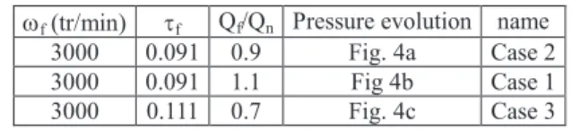
Transient behaviors have been investigated by performing fast start-ups of the pump at several flow rates. All data are obtained for a final rotation speed equal to 3000 rpm. Tests have been conducted for various values of flow rate and cavitation number. The whole tests have been classified into three different cases according to their pressure evolutions: “low frequency oscillations” (case 1), “high frequency fluctuations” (case 2), “water hammer” (case 3). For each case, pressure evolutions of a reference fast start-up are presented hereafter. The final operating points of these fast starts-ups are given in table 2.
wf (tr/min) tf Qf/Qn Pressure evolution name
3000 0.091 0.9 Fig. 4a Case 2 3000 0.091 1.1 Fig 4b Case 1 3000 0.111 0.7 Fig. 4c Case 3 Table 2 : Final operating point for the three reference cases of fast
start-ups
In most of the cases, pressure signals evolutions are similar to the one drawn in figure 4a (case 2). The pressure at pump suction, after the initial fall, remains completely stable during most of the start-up (0.25s < t < 0.45s). The pressure at delivery is characterized by a significant drop at the end of the start-up, which may be related to the temporary decrease of the pump head because of cavitation on the blades. The delivery signal also exhibits high frequency fluc-tuations whose maximum amplitude is about 50% of the pump head. This may be due to vapour collapse at the pump outlet.
For high flow rates (at least 1.1 Qn) slightly different pressure signals are obtained (figure 4b). Low frequency oscillations of the delivery pressure can be observed at the end and after the transient period. This particular behaviour (case 1), may be due to the ob-struction generated by pressure side cavitation on the blades: such blockage results in a significant decrease of the pump head. Low amplitude pressure oscillations can also be observed on the inlet pressure signal, which suggests that this phenomenon is related to a surge type instability that affects the whole pump.
A third typical pattern of the pressure signals is obtained for in-termediate values of the cavitation number and lower flow rates. In such conditions of moderate cavitation, a pressure peak is obtained at the pump suction at the end of the transient (figure 4c). Note that
Geometric specifications Hydraulic parameters
Inlet vane angle 32,2° wn 2900 rpm
Outlet vane angle 23° ws 0,24
Number of vanes 5 Qn 23 m3/h
Inlet diameter D1 38,5 mm DPn 4,9.105 Pa
Outer diameter D2 202,5 mm
a peak of similar magnitude occurs also at the same time at delivery, although it is not so visible because of high frequency pressure fluctuations. Such simultaneous pressure jumps can be associated with a water hammer phenomenon, as it was previously stated by Tanaka et al. (Tanaka and Tsukamoto, 1999b). This configuration corresponds to the case 3.
The whole tests performed in cavitating conditions have been classified into these three different categories of transients, and the resulting map is drawn in figure 5. It confirms that large scale oscillations systematically occur at high flow rate and in conditions of developed cavitation, while water hammer phenomena are de-tected at lower flow rate and for a moderate development of cavi-tation.
For cases 1 to 3, a physical analysis has been proposed by Duplaa et al (2010) to explain the evolution of the pump head during the start-up. It has been shown that low final flow rates usually enable to reach at the end of the start-up low cavitating conditions, whereas increasing the final flow rate results in more developed cavitating conditions, leading to progressive head drop of the pump. Conversely, low final flow rates result in the occurrence of water hammer phenomena that may be related to the complete sudden collapse of the vapour in the pump and/or the inlet pipe.
Figure 4 : Pressure evolutions a) Case 2 – b) Case 1 – c) Case 3)
Figure 5 : Classification of the start-ups
3. X-RAYS MEASUREMENTS
3.a. Specific Experimental Device
The principle of these non intrusive measurements is based on the X absorption by the material. The X-rays alleviation is more im-portant crossing the liquid than the vapor. So, from the signal in-tensity received by the detectors, it is possible to determinate the amount of vapour crossing by the X-rays beam.
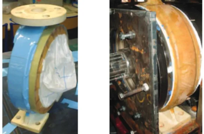
To achieve X-rays measurements the tests ring have to be modified. Actually, the X-beam being absorbed by the material, the X beam absorption by the casing must be limited in order to crossing the impeller with a sufficiently power. For that reason the bronze cas-ing has been replaced by a materiel with a lower density. It has been developed in polyamide by laser sintering. Laser sintering is used to obtain a polyamide part by successive layering, polymerized by a laser (figures 6a and 6b). The main disadvantage of this process is a waterproof lack for pressure upper 1 bar. Composite fibreglass materials, impregnated with resin, have been laid down all around
the casing (figures 7a and 7b). This has allowed making sure it is completely waterproof. Moreover the composite fibreglass material assures the mechanical strength. As the bronze casing, the alumi-num impeller has been replaced by a Plexiglas impeller where the density is lower (Figure 8). The impeller has been manufactured with a 5 axis machine. Note that the impeller geometry is still the same. The flange of the impeller is machined in Plexiglas too. The assembling of two parts is realized by sticking (cyanoacrylate “Loctite 401”).
Figure 6: a) Laser sintering principle b) Casing obtained by sin-tering laser
Figure 7 : a) Laying of composite material on the casing -b) Final result
Figure 8 : Photography of the Plexiglas impeller
A prior dimensioning of mechanical links has been accomplished. Actually, the link between the flange and the impeller on one hand, and the one between the hub and the impeller on the other hand, must tolerate the efforts due to the start-up. Finally, the hub is machined in aluminum with a grooved geometry (see figure 8) in order to tolerate the torque efforts which occurs on it during the fast start-up. Otherwise, the rotation speed of the Plexiglas impeller is limited to 2500 rpm in order to the sticking tolerates the shear stress.
Aluminium grooved hub
So X-rays measurements are realized for a rotation speed equal to 2500 tr/min. However, it has been shown (Duplaa et al, 2010) that a close agreement between dimensionless charts at 2500 rpm and 3000 rpm is obtained for head drop in stabilized and cavitating conditions. It shows that similarity laws can be extended to cavi-tating behavior at such speeds.
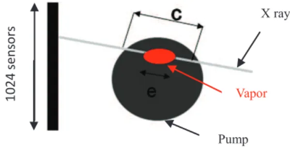
The X experimental setup consists of a X-rays generator on the one hand and 1024 receivers (section equal to 0,4mm*0,3mm) verti-cally positioned on the other hand. Generator and receivers are each pump side opposite in a perpendicular plan to the inlet pipe (Figure 9). The X beam emitted by the generator crosses the casing and the impeller before to be received by the receptors. The acquisition frequency of detectors is equal to 2 kHz and the register time delay is equal to 1,5s. As the other sensors, the detectors are trigged by the electromagnetic clutch. The X beam is sufficiently large in vertically direction to include the entire pump. The width of the X beam in the axial direction is equal to 0,3 mm. The generator and receptors device is so positioned on a motorized plate in order to be able to displace the setup on the axial direction. The entire width of impeller (7mm) can be tested. So it is possible to reconstruct the total vapour volume in the impeller. For security reasons, the x device and the pump are inside a lead structure (figure 10). This last one protects the operators from the X radiations.
Figure 10 : View of the lead structure
3. b. X-Rays Measurements
X-rays measurements have been achieved for different fast start-ups corresponding to the three different cases (low frequency oscillations, water hammer and high frequency fluctuations). The aim is to determinate the density evolution within the impeller during fast start-up in cavitating conditions. For the moment, only results concerning the relative vapor length (e/c) crossed by each
X-ray has been obtained (figure 11). To obtain the temporal density evolutions in the impeller a supplementary treatment of data is necessary and will be soon achieved.
Figure 11: Relative vapour length definition
Measurements have been performed in three plans of the blade to blade channels.Figure 12 shows the results obtained in the middle plan of the blade to blade channel and for each case of fast start-up. The relative vapour length is plotted for the 1024 sensors during the start-up. So, the vertical axis informs on the radial position of the vapour and the horizontal axis informs on the vapour temporal evolution. The colour level indicates the vapour account: dark is relative to the liquid and light to the vapour. The very dark band located on the middle corresponds to the aluminium hub. These data allow estimating the existence time and the radial position of the cavitation in the impeller during the start-up.
On the figure 13 are plotted the relative vapour length profiles viewed by the sensor marked by the line on the figure 12 plots. Unfortunately, temporal density evolutions in the impeller during fast start-up have not been yet obtained. So, in the next paragraph, the density evolutions, which are necessary to the modelling of fast start-ups in cavitating conditions, will be approximated according to the relative vapour length results shown by the figure 13. So, the density evolution then obtained for the start-up “case 1” is given by the figure 14.
Figure 12 : Relative vapour length in the impeller during fast start-ups a) case 2 - b) case 1- c) case3
Figure 13 : Relative vapour length profil a) case 2 - b) case 1- c) case3
Figure 9 : View of X-rays device
X generator 1024 sensors Pump Standard X beam 1 0 2 4 s e n s o r s X ray Pump Vapor 1 0 2 4 s e n s o r s
Figure 14 : Fluid density profil in the impeller during fast start-up ; case 1 : wf=3000rpm, tf=0.091, Qf/Qn= 1.1
4. CAVITATING FAST START-UPS MODELLING
The fast start-up modelling in cavitating conditions is proposed hereafter. This model consists of a model in no cavitating condi-tions adaptation proposed by Dazin et al (2007).
4.1. Fast Start-up Modelling in Non Cavitating Conditions The fast start-up model in no cavitating conditions proposed by Dazin (2007) and denoted hereafter “ECE” model, is based on moment of momentum and energy equations written for the no compressible fluid in the impeller where the domain of control is shown on figure 15. The transient pump head (Eq.1) is conse-quently written as the sum of three terms:
- a steady term
- an angular acceleration term
- an inertial term including the inertial effects in the impeller, the diffuser and the volute.
t
Q
K
t
K
P
P
st
-
+
D
=
D
1r
2w
r
(Eq.1) Whereò
=
2 1tan
(
)
1 R Rdr
r
r
K
b
vol vol d d R R A L A L dr r r b r K =ò
+ + 2 1 . ( )sin ( ) 1 4 1 2 2b
p
K1 and K2 are two constant parameters which depend to the
ge-ometry of the pump.
Figure 15 : Domain of control definition, by Dazin et al (2007)
Additional hypothesis are mentioned by Dazin as :
-The radial component Cr of the velocity is supposed to be de-pending only on the radial position and the time.
-The relative flow angle b depends only on the radial position. -The inertial effects in the diffuser and the volute are modeled by two equivalent pipe length (Ld,Lvol) and sections (Ad, Avol). These
lengths are supposed to be constant and equal to the ones at the final
operating point.
-The hydraulic losses during transient operations, as well as the velocity profiles at the inlet and outlet of the impeller at a given operating point (w, Q) are supposed to be equal to the ones in steady operations at the same operating point. So, the value of the steady term
st
P
D in transient conditions is considered equal to the total head of the pump operating under steady condition.
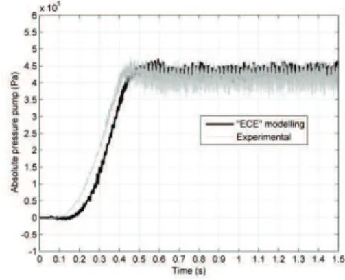
A result obtained from the « ECE » modelling is presented on the figure 16. It concerns the fast start-up defined by wf=3000 rpm,
Qf=1.1Qn. The experimental and model curves are in a good
agreement.
Figure 16 : “ECE” model (wf=3000 rpm, Qf=1.1Qn)
An adaptation of “ECE” model is proposed here in order to mod-elling fast start-up in cavitating conditions. In a first time, the cavitating stationary results are used to adapt the stationary term DPst. In a second time the results of X-rays measurements are used
to take into account the density variations in the impeller during transient period.
4.2. Pseudo-Steady Model
In order to adapt the stationary term DPst, the transient cavitation
development is considered as a quasi-stationary states succession. For each time of the cavitating fast start-up, the inlet pressure Ps is defined from parameters (w, ws, Q, t). For each value of Ps, the
corresponding superpressure drop is determined from stationary drops (figure 3). A bilinear interpolation allows evaluating any stationary superpressure drop corresponding to a given operating point. Then, for each temporal sample of fast start-up, these cor-responds superpressure drops are subtracted from the superpressure given by the ECE modelling. A first estimation of the superpressure delivered by the pump in cavating fast start-up is then obtained. So the new stationary term (DPst-cav) takes into account the influence of
the stationary cavitation development of the pump. The pressure of the pump is then given by the equation 2.
t
Q
K
t
K
P
P
cav st cav
-
+
D
=
D
- 1r
2w
r
(Eq.2)For the fast start-up where the final operating point is defined by wf
=3000 rpm, tf=0.091 and Qf/Qn=1.1, the result of this
pseu-do-steady adaptation is plotted on figure 17. The “ECE” model and the experimental curves are added on the figure in order to identify the influence of the stationary cavitation within the modelling. The two modelling are the same as long as the cavitation don’t modify the stationary term. The experimental curve presents two pressure drops (t=0.36s and t=0.58s). The both pressure drops are predicted by the pseudo-steady model but only the second is cor-rectly predicted (qualitatively and quantitatively). The first one is underestimated and predicted too late. The figure 18 shows that the second drop takes place for an operating point located in the sta-tionary performance drop. So the second drop is due to stasta-tionary
effects and the prediction is correct. This is not the case for the first drop which occurs at t=0.36s. At this moment, the corresponding operating point is located before the stationary performance drop (figure 18) ; so the first drop is mainly due to transient effects and it can’t be correctly predict by the model.
Figure 17 : Pseudo-steady modelling (wf=3000 rpm, Qf=1.1Qn,
tf=0.091) 0 0,05 0,1 0,15 0,2 0,25 0,3 0,35 0,4 0,45 0,5 0,55 0,6 0,02 0,04 0,06 0,08 0,1 0,12 0,14 0,16 t Y d = 1,47E-2 d = 1,68E-2 d = 1,89E-2 d = 2,1E-2 d = 2,32E-2 d = 2,53E-2
Figure 18 : Characterization of the two transient drops inception
4.3. Variable Density Model
To improve the fast start-up model in cavitating conditions, the density evolution in the impeller is taken into account. Then, the pump pressure is now written as:
t
Q
K
t
K
P
t
P
cav st cav
-
+
D
=
D
_ 1 21000
)
(
r
w
r
r
(Eq.3)Here, the transient density evolution is only taken into account in the pseudo-stationary term.
The figure 19 presents the result obtained for the start-up with the same final operating point. It can be observe that the prediction is clearly improved. The first drop is now correctly expected (time and amplitude).
Figure 19 : Variable density modelling (wf=3000 rpm, Qf=1.1Qn,
tf=0.091)
Moreover, the model shows a pressure rebound around t=0,5s. This rebound is correlated with the density rebound occurs at the same moment (figure 14). Maybe it doesn’t appear on the experimental curves because of the important noise.
Finally, on the basis of these results, the good agreement between the “variable density modelling” and experimental curves means that the influence of the cavitation on the transient terms is not significant. To take into account the transient density evolution is very important but not its influence on the transient terms. This last aspect could be important to model the water hammer phenomena. Actually, note the transient terms of equation 3 are obtained for non compressible flow. In cavitating conditions, others transients terms due to the density temporal variation must be written.
CONCLUSION
The three different cases of fast start-ups in cavitating conditions have been remembered. This aim of this paper is to propose a cavitating fast start-ups modelling. In order to predict the pump performance during cavitating fast start-ups, a non cavitating model has been adapted first taking into account the performance drop of the pump in steady conditions, secondly taking into account the transient density evolution in the impeller. The first step of adapta-tion allows predicting correctly the transient pump performance where the cavitation and the transient terms no much together interact. The modelling obtained with the second step is very sat-isfactory for the whole fast start-up. For obtained the density evo-lution, high frequency X rays measurements have been performed in the impeller during the transient for different final operating points. The X rays results have to be analysed and exploited moreover. However, they already show different vapour com-portment in the impeller with the considered case of fast start-up. These different vapor evolutions are correlated with the pressure evolutions. Today the model is based on the non compressible equations written for the non cavitating model “ECE”. Although the results also obtained seem satisfactory, the compressible flow equations must be written. Actually, supplementary unsteady terms appear in the compressible equations and it would be interesting to evaluate their influence on the prediction of cavitating fast start-ups.
First experimental drop
ACKNOWLEDGEMENTS
The present work was performed in the scope of a research grant from the CNES (French Space Agency) and SNECMA Moteurs. The authors wish to express their gratitude to SNECMA Moteurs and the CNES for their continuous support.
REFERENCES
Coutier-Delgosha O., Stutz B., Vabre A., Legoupil S., 2007, “Analysis of cavitating flow structure by experimental and nu-merical investigations”, J. of Fluid Mechanics, 578, 171-222
Dazin A., Caignaert G., Bois G., 2007, “Experimental and Theoretical Analysis of a Centrifugal Pump During Fast Starting Period”, ASME J. Fluids Eng., 129, pp. 1436-1444.
Duplaa S., Coutier-Delgosha O., Dazin A., Roussette O., Bois G., Caignaert G., 2008, « Experimental Characterization of a Cavitating Centrifugal Pump During Fast Start-Ups »,
Communi-cation ISROMAC12.
Duplaa S., Coutier-Delgosha O., Dazin A., Roussette O., Bois G., Caignaert G., 2010, “ Experimental Study of a Cavitating Centrifugal Pump During Fast Start-Ups “, ASME J. Fluids Eng., 132, 021301.
Tanaka T., Tsukamoto H., 1999a, “Transient Behavior of a Cavitating Centrifugal Pump at Rapid Change in Operating Con-ditions—Part 1: Transient Phenomena at Opening / Closure of Discharge Valve”, ASME J. Fluids Eng., 121, pp. 841-849.
Tanaka T., Tsukamoto H., 1999b, “Transient Behavior of a Cavitating Centrifugal Pump at Rapid Change in Operating Con-ditions—Part 2: Transient Phenomena at Pump Start-up/Shutdown”,
ASME J. Fluids Eng., 121, pp. 850-856.
Tanaka T., Tsukamoto H., 1999c, “Transient Behavior of a Cavitating Centrifugal Pump at Rapid Change in Operating Con-ditions—Part 3: Classifications of Transient Phenomena”, ASME J.
Fluids Eng., 121, pp. 857-865.
Tsukamoto H., Yoneda H., Sagara K., 1995, “The Response of a Centrifugal Pump to Fluctuating Rotational Speed”, ASME J.
Fluids Eng., 117, pp 479 – 484.
Picavet A., Barrand J.P., 1996, “Fast Start-up of a Centrif-ugal Pump – Experimental Study”, Pump Congress, Karlsruhe, Deutschland.
Bolpaire S., Barrand J.P., Caignaert G., 2002, “Experi-mental Study of the Flow in the Suction Pipe of a Centrifugal Pump Impeller : Steady Conditions Compared With Fast Start-up”, Int. J.
Rotating Machinery, 8(3), pp. 215-222.
Lefebvre P.J., Barker W.P., 1995, “Centrifugal Pump Per-formance During Transient Operation”, ASME J. Fluids Eng., 117, pp. 123 – 128.
Ghelici N., 1993, “Etude du Régime Transitoire de Dé-marrage Rapide d’une Pompe Centrifuge”, Ph.D. thesis, Ecole Nationale Supérieure d’Arts et Métiers, Lille, France.
Picavet A., 1996, “Etude des Phénomènes Hydrauliques Transitoires lors du Démarrage Rapide d’une Pompe Centrifuge”, Ph.D. thesis, Ecole Nationale Supérieure d’Arts et Métiers, Lille, France.
Bolpaire S., 2000, “Etude des Ecoulements Instationnaires dans une Pompe en Régime de Démarrage ou en Régime Etabli “, Ph.D. thesis, Ecole Nationale Supérieure des Arts et Métiers, Lille, France.
Stutz B., Legoupil S., 2003, X-ray Measurements within unsteady cavitation. Exp. In Fluids, 35(2), 130-138.
Walid H., 2005, « Développement d’un système tomogra-phique pour l’étude expérimentale du volume de vapeur présent au sein des turbopompes des machines spatiales », Ph.D. Institut National Polytechnique de Grenoble.