Science Arts & Métiers (SAM)
is an open access repository that collects the work of Arts et Métiers Institute of Technology researchers and makes it freely available over the web where possible.
This is an author-deposited version published in: https://sam.ensam.eu Handle ID: .http://hdl.handle.net/10985/19556
To cite this version :
Abdelhak MEKAHLIA, Eric SEMAIL, Franck SCUILLER, Hussein ZAHR - Impact of Winding Parameters on Torque Level under Harmonic Injection in Multiphase Induction Machine - In: IECON 2019 - 45th Annual Conference of the IEEE Industrial Electronics Society, Portugal, 2019-10-16 - IECON 2019 Conference - 2019
Any correspondence concerning this service should be sent to the repository Administrator : [email protected]
Impact of Winding Parameters on Torque Level
under Harmonic Injection in Multiphase Induction
Machine
Abdelhak MekahliaUniv. Lille, Centrale Lille, Arts et Metiers ParisTech, HEI, HeSam, EA
2697 - L2EP - Laboratoire d’Electrotechnique et d’Electronique de Puissance. Lille, France. Institut Vedecom. Versailles, France. [email protected] Eric Semail
Univ. Lille, Centrale Lille, Arts et Metiers ParisTech, HEI, HeSam, EA
2697 - L2EP - Laboratoire d’Electrotechnique et d’Electronique de Puissance. Lille, France. [email protected] Hussein Zahr Institut Vedecom. Versailles, France. [email protected] Franck Scuiller
IRENAV – Research Institute of Naval Academy, BCRM Brest – EN/GEP
Brest, France [email protected]
Abstract—Multiphase induction machines have the advantage of producing torque under different current harmonics. Theoretically, with some simplifications, the maximum produced torque can be considered proportional to the harmonic winding factor related to the injected current harmonic. However previous work has shown that this theoretical proportionality between the maximum developed torque and harmonic winding factors is not obtained in the case of a five-phase induction machine with eight-poles and fractional-slot tooth concentrated winding. This paper aims to investigate the effect of winding parameters, especially phase number, fundamental polarity and stator slots number, on the torque production in multiphase induction machine under harmonics injection. A comparative study is done between four five-phase winding configurations, with the same geometry and copper volume, under both first and third harmonic injection. Finally, a special 15-phase winding presenting better consistency between maximum developed torque and harmonic winding factors is proposed.
Keywords—Multiphase Induction Machine, Harmonic Winding Factors, Harmonics Injection, Fundamental Polarity.
I. NOMENCLATURE
- spp: Number of slots per pole and per phase - Ns: Number of stator slots
- p1: Number of pole-pairs under first harmonic
injection (called fundamental polarity in the paper) - ph: Number of pole-pairs (or the polarity) under
injection of harmonic “h”
- khi: Winding factor related to harmonic “i”
- Dph-pp: Coils distribution vector per phase and per
pole-pair
- ωs: Stator pulsation (stator current fundamental
frequency multiplied by 2π)
- ωr: Rotor pulsation (rotor current fundamental
frequency multiplied by 2π) - Ωmec: Mechanical speed
- s: Slip.
- F-E: Finite Element
II. INTRODUCTION
The multiphase induction machine is becoming more and more attractive in several applications as automotive [1], naval
[2] and aeronautics [3]. Thanks to the possibility of producing smooth torque by more than one current harmonic, unlike the three-phase machine, the multiphase machines offer more degrees of freedom, especially regarding torque density improvement [4] [5], speed-range extension [6] and fault-tolerant operating [7] [8]. This kind of machines is supplied by multiphase inverters for variable speed operations.
Classically in a three-phase induction machine, overlapping windings with distributed coils are widely used, thanks to their sinusoidal winding function which permits to optimize machine performance especially reduction of torque ripple [9]. More attractive windings regarding the ease of manufacturing like tooth concentrated windings, have a rich space harmonics content, and they are not considered appropriate for three-phase machines, where the presence of harmonics impacts negatively the performances.
In multiphase machines, the harmonics are separated into different sets. A harmonic of one set does not interact with other harmonics from another set. Hence, the main harmonic from each set can be injected to produce torque without impacting its quality. In this case, not only overlapping windings can be chosen, but also other configurations like tooth-concentrated windings. In fact, the presence of harmonics is useful for torque production and enhancement [10], [11].
While torque is produced by more than one current harmonic, one should determine which harmonics have a high torque capability. This is possible by calculating the harmonic winding factors resulting from the winding distribution. Considering classical theoretical approach these factors reflect the level of developed torque for each injected harmonic. Nevertheless, a previous study with F-E modeling has shown that in the case of five-phase induction machine with a fundamental polarity p1=4, and a tooth concentrated winding
with spp=0.5, even though the third harmonic winding factor is higher than the first one, the developed torque under third current harmonic injection is lower than the one under first current harmonic supply [12].
In this paper, the impact of winding parameters on torque level in multi-phase induction machines is investigated. Firstly, the consistency between harmonic winding factors and maximum developed torque under both first and third current
harmonics supply is studied for different five-phase integral-slot pole-concentrated windings.
These windings are chosen, because they allow to maximize the first and third harmonics winding factors and cancel even-order winding factors.
Finally, a special 15-phase winding, with relatively short end-coils, and which leads to a better consistency between harmonic winding factors and torque capability under different current harmonics injection is proposed.
All the machines presented in this paper are supplied by sequential current harmonics. This supply mode allows to improve the speed range of multiphase machines [6][13][14].
III. CHOSEN FIVE-PHASE WINDINGS
In a previous paper on the effect of the rotor bar number on the performance of five-phase induction machine [12], F-E simulation results were presented for a five-phase induction machine, with the following parameters :
- 20 stator slots
- 4 pole-pairs (fundamental polarity) - Tooth concentrated winding with spp = 0.5 - First harmonic winding factor kh1 = 0.59
- Third harmonic winding factor kh3 = 0.95
- 5 different rotor bar numbers: 13, 18, 35, 64, 65 This study has shown that the maximum developed torque under the third current harmonic supply is lower than that under the first harmonic for all bar numbers, while the third harmonic winding factor kh3 (0.95) is higher than kh1 (0.59).
The winding chosen in this study generates both odd and even space harmonics [12], and the second space harmonic has the same winding factor as the third harmonic. In this case the interaction between the second space harmonic and the third current harmonic produces a negative torque [10] (both are in the same harmonics set) which complicates the interpretation of torque production under third current harmonic injection.
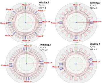
To avoid that, in this paper, we have chosen four overlapping windings, that do not generate space harmonics of order multiple of 2p1.
A. Windings specifications
Four five-phase winding configurations are chosen: - Winding 1: Ns = 40, p1 =4, spp =1
- Winding 2: Ns = 20, p1 =2, spp =1
- Winding 3: Ns = 40, p1 =2, spp =2
- Winding 4: Ns = 20, p1 =1, spp =2
Fig. 1 shows the four machines geometry with coils distribution for phase 1.
To determine the harmonic winding factors, the Discrete Fourier Transform (DFT) of conductor distribution function inside the slots can be used [15], TABLE I shows the calculation of these factors from the first to the fourth space harmonic.
In a five-phase induction machine, there are two independent sets of harmonics [16]. The primary set contains the harmonics: 1, 4, 6, 9…, the secondary set contains the harmonics: 2, 3, 7, 8…, and all the multiples of 5 (number of phases) belong to the zero sequence. In the case of overlapping
windings all even harmonics are null, so if the first current harmonic is injected, it interacts with the 1st, 9th, 11th … space
harmonics, and the third current harmonic interacts with the 3rd, 7th, 13th …space harmonics.
Fig. 1: Machines geometry and coils distribution in phase 1. TABLEI. HARMONIC WINDING FACTORS DETERMINATION
Winding Dph-pp kh1 kh2 kh3 kh4 1 [1 0 0 0 0 -1 0 0 0 0] 1 0 1 0 2 [1 0 0 0 0 -1 0 0 0 0] 1 0 1 0 3 [1 1 0 0 0 0 0 0 0 0 -1 -1 0 0 0 0 0 0 0 0] 0.99 0 0.89 0 4 [1 1 0 0 0 0 0 0 0 0 -1 -1 0 0 0 0 0 0 0 0] 0.99 0 0.89 0 B. Machines dimensions
For the 4 winding configurations, the same stator and rotor dimensions and the copper volume are taken. Global dimensions and parameters are specified in the TABLE II.
TABLEII. GLOBAL MACHINES DIMENSIONS AND PARAMETERS
Parameters Value
Stator external diameter 246 mm Stator internal diameter 160 mm
Shaft diameter 86 mm
Airgap length 0.5 mm
Machine length 157 mm
Rotor bar number 65
Stator copper volume (without considering end coils)
484 cm3
Rotor copper volume (without considering end connection)
458 cm3
Rated phase current (RMS) 173 A
These dimensions are close to some examples of machines used in traction applications like Tesla Model-S asynchronous motor and ISCAD concept [14].
Rotor bar number is chosen from results of previous work [12].
IV. FINITE-ELEMENT SIMULATIONS
The objective of these simulations is to study the torque capability of the four machines under both first and third current harmonic supply.
For each machine, the torque curves in function of rotor pulsation are determined using Maxwell software (Ansys), under the rated stator RMS current.
All simulations are done with a time step size equal to the period of the injected stator current divided by 20. An element length-based mesh refinement is imposed on: the stator coils, rotor bars and on a circle drown in the middle of the airgap.
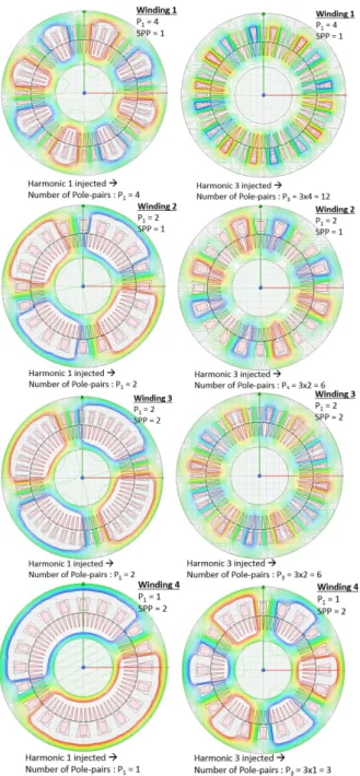
A. Poles distribution under first and third harmonic supply
Cartographies of flux lines in the 4 machines are shown in Fig. 2. These maps clearly show the number of magnetic poles induced in the machine by the current supply, that changes from p1 to 3p1 when the third current harmonic supplies the
winding.
Fig. 2: Poles distribution under first and third harmonic supply
B. Torque analysis under rated current
To determine the maximum torque that can develop the machines in steady state, F-E simulations, with parametric variation of the slip, have been done. The slip is defined for all supply modes as below:
= . (1) Where the stator pulsation ωs is defined as:
= ℎ. 2. . (2) fs1 is the stator current frequency under the first harmonic
supply, equal to 50 Hz for all simulations.
The number of pole-pairs changes with injected harmonic range. It can be defined as:
= ℎ. (3) Where “h” is the rank of the injected harmonic.
So, the rotor currents fundamental pulsation can be defined as:
= . (4) In the next four figures (from Fig. 3 to Fig. 6) the torque curves for the 4 machines are drawn according to the rotor currents fundamental pulsation defined in equation (4).
F-E simulations with parametric variation are time-consuming, especially for induction machine where it takes relatively long time to reach the numerical steady-state due to rotor currents establishing (around 20 stator current periods, which takes many hours depending on the step time). For the chosen machines, to determine precisely the torque variation, for a given slip value, a transient simulation of more than 600 time-points (for example simulation time of 600 ms with a step of 1 ms) must be done. Hence only some slip-points are simulated (slip values around the maximum torque point), that explains why the torque curves in the next figures do not start from zero-slip point, and do not have the same length.
TABLE III reports the obtained maximum torque points for the 4 machines under first and third harmonic supplies. Torque ripple values are determined basing on torque variation after numerical steady-state is reached by dividing the peak-to-peak value by the mean value. The obtained torque ripple levels are considered acceptable for the 4 machines.
Fig. 3: Mean torque curves for the winding 1
For the winding 1 (Fig. 3), the fundamental polarity is p1=4, the maximum torque mean value under the first
0 5 10 15 20 25 30 35 40
Rotor pulsation (rad / s) 0 50 100 150 200 250
300Mean torque in function of rotor pulsation - Winding 1
Current harmonic 1 - 16 simulation points Current harmonic 3 - 14 simulation points
X: 13.19 Y: 257.2
X: 37.7 Y: 91.77
harmonic supply is 257 N.m, even though the first and third space harmonic winding factors kh1 and kh3 are equal to 1, the
maximum developed torque under the third harmonic supply is just 36% lower than the torque with the first current harmonic.
By using the winding 2 (Fig. 4), the fundamental polarity is reduced to p1=2, the first current harmonic maximum torque
is reduced to 236 N.m (8% of reduction from winding 1) due to the number of stator slots which is going from 40 to 20 (coupling factor between stator and rotor is better with a higher number of slots). However, the maximum torque developed under the third harmonic supply is enhanced with this winding (92% of enhancement comparing to winding 1), but it is still lower than the first current harmonic maximum torque, whereas kh3=kh1=1. Flux leakages are probably
increased with the third harmonic current supply, thus justifying this reduction.
Fig. 4: Mean torque curves for the winding 2
So, we can analyze the low torque capability under the third harmonic injection in winding 1, by the high number of pole-pairs p3=12 (24 magnetic poles) which induces important
rotor losses, in Fig. 2 it can be observed that the number of induced magnetic poles under 3rd harmonic for this winding is
very high for the 40 stator slots. Furthermore, the rotor pulsation at third harmonic maximum torque for the winding 1 is 37.7 rad.s-1 (almost double of the value for winding 2),
hence the rotor losses are more important for a higher rotor currents pulsation.
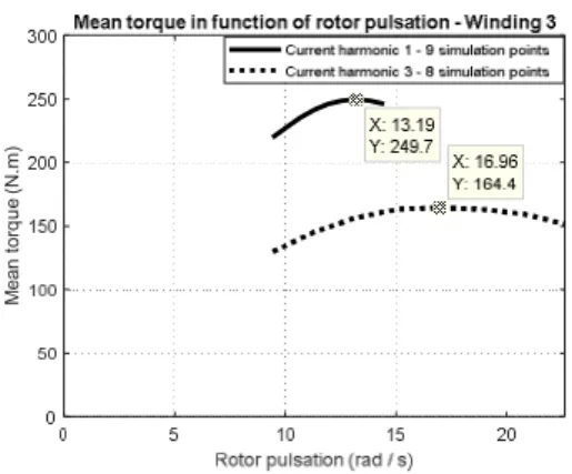
Fig. 5: Mean torque curves for the winding 3
For the winding 3 (Fig. 5), the fundamental polarity is kept p1=2, and the number of stator slots is again 40. In this case
the number of slots per pole and per phase equals two, thus reducing the winding factors (kh1=0.99 and kh3=0.89).
Maximum developed torque under first harmonic supply reaches 250 N.m (6% of enhancement comparing to winding 2) thanks to a higher number of stator slots, whereas torque
level under third harmonic supply is slightly reduced due to a lower third harmonic winding factor (kh3-winding3 is 89% of k h3-winding2).
For the winding 4 (Fig. 6), the harmonic winding factors are the same as with the winding 3 (kh1=0.99 and kh3=0.89), as
shown in TABLE I. The fundamental polarity is p1=1 so the
polarity under third harmonic injection passes from 6 to 3 pole-pairs, thanks to that the torque level under this harmonic is enhanced comparing to the winding 3 (33% of enhancement). However, the torque under the first harmonic supply is significantly reduced (55% of reduction). In fact, the stator and rotor yoke height are not well adapted to a such low polarity (p1=1), so the saturation effect is very significant in
these regions.
Fig. 6: Mean torque curves for the winding 4
TABLEIII. MAXIMUM DEVELOPED TORQUE AND ROTOR PULSATIONS VALUES
Winding 1 Winding 2 Winding 3 Winding 4
Harmonic H1 H3 H1 H3 H1 H3 H1 H3 Pole-pairs 4 12 2 6 2 6 1 3 khi 1 1 1 1 0.99 0.89 0.99 0.89 Max torque (N.m) 257 92 236 177 250 164 112 218 Torque Ripple (%) 1.3 3.8 1.2 6 0.5 2.5 4.3 7.3 Rotor pulsation @Max torque (rad.s-1) 13.2 37.7 13.2 20.7 13.2 17 12.6 9.4
Fig. 7: Maximum torque improvement by stator yoke extension with the winding 4
To confirm the reason of the torque reduction under first current harmonic for the winding 4, new simulations are done with an extended stator yoke height (from 21 mm to 42 mm),
M e a n t o rq u e ( N .m )
so the volume of the machine is increased of 17.8% (copper volume is not increased). The results are shown in Fig. 7. Torque enhancement thanks to stator yoke extension is of 43% under first harmonic supply, and the torque level is still lower than the one under 3rd harmonic supply. In fact, it is not only
stator yoke that must be extended, but also rotor yoke which is highly saturated, as seen in Fig. 2 (Map for “Winding 4” under 1st harmonic). That was not done in this study because
it would modify completely the dimensions of the machine. For the winding 4, we can conclude that the machine volume and weight must be increased to obtain the suitable torque level under first harmonic, so the torque density of the machine is very low comparing to winding 2 and 3, even if it develops a higher torque under 3rd harmonic.
Through this investigation of five-phase windings, it can be concluded that it is complicated to conceive a five-phase machine with the suitable consistency between maximum developed torque and harmonic winding factors. For this reason, a higher number of phases, could offer more degrees of freedom regarding the winding design, as presented in the next section.
V. 15-PHASE PROPOSED WINDING
As seen in the previous section, in the case of five-phase induction machine, even with overlapping windings (where even harmonics are null) it is difficult to choose a winding ensuring a consistency between developed torque under harmonics injection and harmonic winding factors.
With a higher number of phases, the harmonics are more and more separated into different sets, so the presence of even space harmonics could be advantageous, on the contrary of three-phase or five-phase machines.
If we take the example of 15-phase machine, the harmonics are separated into 7 sets (and one zero-sequence) [16], as described in TABLE IV. In this case, the even harmonics are useful and could be injected to produce a torque of good quality thanks to the reduced harmonics interactions (comparing to 3-phase and 5-phase machines), so the use of overlapping winding is no longer preferable.
TABLEIV. DISTRIBUTION OF HARMONICS INTO 7 SETS FOR
15-PHASE WINDING
Sets Harmonics ranges
1st set 1, 14, 16… 2nd set 2, 13, 17… 3rd set 3, 12, 18… 4th set 4, 11, 19… 5th set 5, 10, 20… 6th set 6, 9, 21… 7th set 7, 8, 22… Zero-sequence 15, 30, 45 …
As seen before, the fundamental polarity of a multiphase winding for induction machine must be as low as possible. In the case of a five-phase winding, if we choose p1=1 we can
only increase the number of stator slots, thus resulting in higher “spp”, and consequently reducing the harmonic winding factors. In the other hand, with p1=1 the stator and
rotor yokes must be enlarged to develop the suitable torque level (as seen for the winding 4). However, in the case of
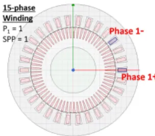
15-phase winding, we can choose a fundamental polarity p1=1,
with an acceptable number of stator slots and a low “spp” (for example: Ns=30, p1=1 and spp=1). Furthermore, the use of the
first current harmonic is not necessary because we could have higher harmonic winding factors for the other harmonics which is the case of the proposed winding shown in Fig. 8. The 15-phase machine has the same global dimensions and copper quantity as the simulated five-phase machines (TABLE II).
This winding has the advantage of short end-coils comparing to overlapping winding (especially when p1=1), the
harmonic winding factors are shown in TABLE V.
Fig. 8: 15-phase machine geometry and coils distribution in phase 1. TABLEV. HARMONIC WINDING FACTORS OF THE PROPOSED
15-PHASE WINDING.
Harmonic 1 2 3 4 5 6 7
Winding factors
0.31 0.59 0.81 0.95 1 0.95 0.81 This machine was simulated under 3rd and 4th current
harmonics injection (kh3 = 0.81, kh4 = 0.95). The amplitude of
current was calculated to keep the same current density per conductor and the obtained RMS value is 69 A.
Poles distribution under both injected harmonics is shown in Fig. 9.
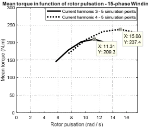
Fig. 9: Poles distribution under third and fourth harmonic supply By the same way as explained previously, the torque curves in function of rotor pulsation are determined by FE parametric simulations, and shown in Fig. 10.
Maximum developed torque under third harmonic supply is 209.3 N.m, the torque ripple was calculated, and it is of 2%. For the fourth harmonic supply the maximum torque is 237.4 N.m with torque ripple of 2.8%. So, for both supplying modes the torque is of a good quality. As expected by the harmonic winding factors, we develop more torque with the 4th current
harmonic than the 3rd one.
= 0.85 & = 0.88 (5) We can conclude that the developed torque under each current harmonic injection, is coherent with the harmonic winding factors for the proposed 15-phase winding.
Fig. 10: Mean torque curves for the proposed 15-phase machine VI. CONCLUSION
In multiphase induction machines, several current harmonics can be injected to produce torque. Hence, to design a multiphase winding for induction machine, the coils distribution must be chosen according to the suitable torque capability under different current harmonics. In fact, maximum torque level under a harmonic “i” is reflected by the harmonic winding factor “khi” according to the classical
theoretical approach.
In this study, the torque capability under first and third harmonic supplies was investigated with four different five-phase windings, with the same machine geometry and copper volume. F-E simulations were done to determine the maximum torque under rated phase current for each machine. The results have shown that:
- A high fundamental polarity impacts the torque capability under the third harmonic supply (due to the important level of rotor losses).
- A high number of stator slots enhances slightly the torque capability.
- A very low fundamental polarity (p1 = 1) requires a
bigger magnetic circuit (extended stator and rotor yokes) to develop the suitable torque under first harmonic supply.
Through the study of the chosen five-phase windings, it has been concluded that is complicated to design a five-phase induction machine with a good consistency between torque capability, under harmonics injection, and harmonic winding factors. In fact, the number of induced magnetic poles in the machine must be in an acceptable range. In our case, for the winding with p1=2, the torque capability is good under first
harmonic supply but not under the third one, where 12 magnetic poles are induced (p3=6), in the other hand, the
winding with p1=1 had a relatively good torque capability
under third harmonic supply, but not under the first one, where the stator and rotor yokes must be extended due to the very low polarity.
The raise of number of phases, offers more degrees of freedom regarding the winding choice. The harmonics are separated more and more into independent sets, which allow to choose winding distributions with both odd and even space harmonics. An example of 15-phase winding was presented, and it has been shown that the developed torque under 3rd and
4th current harmonics supplies, had a good consistency with
the harmonic winding factors. In fact, for this machine, the used harmonics induce an acceptable number of magnetic pole-pairs (3 and 4).
REFERENCES
. [1] A. Patzak, F. Bachheibl, A. Baumgardt, G. Dajaku, O. Moros,
and D. Gerling, “Driving range evaluation of a multi-phase drive for low voltage high power electric vehicles,” in International
Conference on Sustainable Mobility Applications, Renewables and Technology (SMART), 2015, pp. 1–7.
[2] Z. Liu, J. Wu, and L. Hao, “Coordinated and fault-tolerant control of tandem 15-phase induction motors in ship propulsion system,” IET Electr. Power Appl., vol. 12, no. 1, pp. 91–97, 2017.
[3] O. Grigore-Müler and M. Barbelian, “The simulation of a multi-phase induction motor drive,” in 12th International Conference
on Optimization of Electrical and Electronic Equipment, OPTIM 2010, 2010, vol. 1, pp. 297–306.
[4] M. Mengoni, L. Zarri, A. Tani, L. Parsa, G. Serra, and D. Casadei, “High-torque-density control of multiphase induction motor drives operating over a wide speed range,” IEEE Trans.
Ind. Electron., vol. 62, no. 2, pp. 814–825, 2015.
[5] A. S. Abdel-Khalik, M. I. Masoud, S. Ahmed, and A. M. Massoud, “Effect of current harmonic injection on constant rotor volume multiphase induction machine stators: A comparative study,” IEEE Trans. Ind. Appl., vol. 48, no. 6, pp. 2002–2013, 2012.
[6] B. S. Umesh and K. Sivakumar, “Pole-Phase Modulated Multiphase Induction Motor Drive with Reduced Torque Ripple and Improved DC Link Utilization,” IEEE Trans. Power
Electron., vol. 32, no. 10, pp. 7862–7869, 2017.
[7] A. Tani, M. Mengoni, L. Zarri, G. Serra, and D. Casadei, “Control of multiphase induction motors with an odd number of phases under open-circuit phase faults,” IEEE Trans. Power
Electron., vol. 27, no. 2, pp. 565–577, 2012.
[8] M. Bermudez, I. Gonzalez-Prieto, F. Barrero, H. Guzman, M. J. Duran, and X. Kestelyn, “Open-Phase Fault-Tolerant Direct Torque Control Technique for Five-Phase Induction Motor Drives,” IEEE Trans. Ind. Electron., vol. 64, no. 2, pp. 902–911, 2017.
[9] T. A. Lipo, H. A. Toliyat, and J. C. White, “Analysis of a Concentrated Winding Induction Machine for Adjustable Speed Drive Applications - Part 1,” IEEE Trans. Energy Convers., vol. 6, no. 4, pp. 679–683, 1991.
[10] A. S. Abdel-khalik and S. Ahmed, “Performance Evaluation of a Five-Phase Modular Winding Induction Machine,” IEEE Trans.
Ind. Electron., vol. 59, no. 6, pp. 2654–2669, 2012.
[11] W. Kong, J. Huang, R. Qu, M. Kang, and J. Yang,
“Nonsinusoidal Power Supply Analysis for Concentrated-Full-Pitch-Winding Multiphase Induction Motor,” IEEE Trans. Ind.
Electron., vol. 63, no. 1, pp. 574–582, 2016.
[12] A. Mekahlia, E. Semail, F. Scuiller, T. Hamiti, and R. Benlamine, “Effect of Rotor Bar Number on Performance of Five-Phase Induction Machine for Traction,” in XIII International
Conference on Electrical Machines (ICEM), 2018, pp. 185–190.
[13] S. Sadeghi, L. Guo, H. A. Toliyat, and L. Parsa, “Wide operational speed range of five-phase permanent magnet machines by using different stator winding configurations,” IEEE
Trans. Ind. Electron., vol. 59, no. 6, pp. 2621–2631, 2012.
[14] G. Dajaku, F. Bachheibl, A. Patzak, and D. Gerling, “Intelligent Stator Cage Winding for Automotive Traction Electric Machines,” in EVS28 International Electric Vehicle Symposium
and Exhibition, 2015, pp. 1–8.
[15] F. Scuiller, E. Semail, and J.-F. Charpentier, “General modeling of the windings for multi-phase ac machines,” Eur. Phys. J. Appl.
Phys., vol. 50, no. 3, p. 31102, 2010.
[16] E. Semail, A. Bouscayrol, and J.-P. Hautier, “Vectorial formalism for analysis and design of polyphase synchronous machines,” Eur. Phys. J. Appl. Phys., vol. 22, no. 3, pp. 207–221, 2003. M e a n t o rq u e ( N .m )