Science Arts & Métiers (SAM)
is an open access repository that collects the work of Arts et Métiers Institute of
Technology researchers and makes it freely available over the web where possible.
This is an author-deposited version published in: https://sam.ensam.eu
Handle ID: .http://hdl.handle.net/10985/11935
To cite this version :
Tudor BALAN, Eric BECKER, Laurent LANGLOIS, Régis BIGOT - A new route for semi-solid
steel forging - CIRP Annals - Manufacturing Technology - Vol. 66, n°1, p.297–300 - 2017
Any correspondence concerning this service should be sent to the repository
Administrator : archiveouverte@ensam.eu
Pre-print
A new route for semi-solid steel forging
Tudor Balan, Eric Becker, Laurent Langlois, Régis Bigot
Laboratoire de Conception Fabrication Commande, LCFC (EA 4495), ENSAM – Metz Campus, 4 rue A Fresnel, 57078 Metz, France Submitted by Dorel Banabic
Forging in semi-solid state significantly extends the possibilities of classical hot forging. In order to fully exploit its potential, the process requires a specific and demanding environment, penalizing its industrial deployment. In this context, an alternative route is proposed. In the proposed process, semi-solid zones at the heart of the material coexist with surrounding solid zones within the part. The outcome is an optimized process where the benefits of thixoforging are reached at a significant extent within the classical process framework of hot forging. The paper investigates this proposal up to a full-scale proof-of-concept in an industrial setting.
Forging, Steel, Semi-solid
1. Introduction
Semi-solid forging (SSF) has emerged as a new technology to expand the possibilities of hot forging. Forged products can be produced with more complex and near-net shapes, thinner sidewalls, narrower dimensional tolerances. From the process viewpoint, the forging forces are significantly decreased and less formable materials with higher mechanical properties may be forged. Compared to casting, parts have better mechanical quality and better surface quality [1][2]. These benefits were successfully industrialized for aluminium and magnesium alloys – in particular by the route of rheoforging. The SSF of steel grades has been a topic of research for the last two decades and its feasibility and benefits have been successfully demonstrated, while industrialization still requires further investigation [3].
The main difficulty with steel SSF is related to part quality and tool lifetime. Part quality issues are related to the lack of reproducibility of liquid fraction, as well as segregation effects due to the differential flow of liquid and solid phases within the billet. Tool lifetime is challenged by the extremely high temperature of the part (beyond 1350°C) and direct contact of the tools with liquid steel [4]. Tools or inserts made of ceramic materials behave better than tool steels in these high temperature conditions but are very sensitive to tensile mechanical loading and shock, while implying additional costs. Consequently, numerous research teams investigated the possibility to use tool steels for SSF tooling [5][6][7].
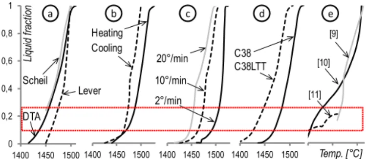
In most investigations, the SSF is performed at a given liquid fraction, uniform over the entire feedstock. This target is very challenging to achieve, due to the very narrow temperature ranges that it implies, which are almost impossible to master within industrially robust conditions given the natural scatter of industrial materials, tooling and equipment (Figure 1).
Alternatively, it seems interesting to purposely enforce a strong gradient between the core of the billet (up to 70% solid) and its outer skin (100% solid). In this configuration, the forming force is significantly reduced compared to hot forging (although not as much as for isothermal SSF). This hybrid approach has several additional advantages. If the process is correctly designed, the
tools never get in contact with liquid steel; consequently, the thermo-mechanical loading of the tools is close to hot forging conditions. Billet stability and handling is improved. In turn, the semi-solid core allows for improved material flow, allowing for more complex geometries in less forging steps. The scatter in initial temperature does induce a significant variability of the liquid fraction at core, but its influence on part quality is effectively filtered by the presence of the solid skin. The effects and implication of thermal gradients in semi-solid forming were already studied in the literature [3],[8]. Here, the aim is to take advantage of these effects in setting up a robust SSF process for steel. 0 0,2 0,4 0,6 0,8 1 1400 1450 1500 1400 1450 1500 1400 1450 1500 1400 1450 1500 1200 1300 1400Temp. [°C] Li qu id fra ct io n DTA Lever Scheil Heating Cooling 2°/min 10°/min 20°/min C38 C38LTT [9] a b c d e [10] [11]
Figure 1. The experimental determination of liquid fraction as a function
of temperature is influenced by a) the experimental / calculation method (DTA = Differential Thermal Analysis), b) reheating vs cooling method, c) the heating rate. d) Differences between regular vs thixoforging-specific metallurgical variants of a steel grade are of the same order of magnitude as the previous effects, or as the differences between measurements by different labs (e) [9]-[11].
Such a controlled gradient of initial feedstock properties can be achieved by an optimized heating strategy and considering the full cycle of heating and transfer. Figure 2a illustrates the approach used to obtain the desired liquid fraction gradient. Inductive heating is used with an optimised inductor (longitudinal distribution of coil diameter and pitch) in order to obtain the maximum temperature at an intermediate radius, with a relatively cooler outer surface. In longitudinal direction a uniform temperature distribution is favoured. It is natural, with inductive heating, to obtain a temperature decrease by the ends
of the billet; this effect is however consistent with our objective of a solid skin. As another specificity of inductive heating, the temperature at the very core of the billet would also be slightly smaller than the maximum. But the temperature (and liquid fraction) distribution at the beginning of forging is obtained after transfer from furnace to tool. This short transfer time must be automated and controlled [3] since it induces very rapid thermal evolutions of the billet. It is very difficult to maintain a uniform liquid fraction during this transfer step; in turn, it is achievable to optimize this step in order to guarantee the formation of a continuous solid skin with the desired thickness and uniformity.
visible rolling fibers
surface wrinkles
solidification shrink holes due to
rapid quenching
end of
heating beginning of forging
0 l f 0.2 l f op tim iz ed in du ct io n he at in g co ol in g – ai r a nd to ol a b
Figure 2. a) Principle of temperature gradient creation during induction
heating and transfer to press and b) its trace observed on reference billets quenched after a heating-transfer cycle to reveal the temperature and metallurgical state before SSF: the colder ends preserve traces of fibering and the original outer geometry, while the central zone exhibits the signs of high liquid fraction: solidification shrink holes at core and surface wrinkles at the surface.
The resulting process is a variant of SSF where the benefits of the semi-solid state are partially exploited, while solving the industrialization issues still penalizing the deployment of SSF for steel applications.
In this paper, this new route for semi-solid forging of steels is investigated. Section 2 describes the heating strategy adopted to reach the desired temperature distribution within the billet. Section 3 describes the laboratory experiments used to set up and prove the concept and to optimize the process parameters. Section 4 summarizes an industrial-scale experiment where the tool lifetime was investigated.
2. Thermal control strategy for semi-solid forging
Temperature control is key for a robust SSF process. Previous research has clearly shown that inductive heating is the most appropriate technique for SSF of steels [5][8][13]. The temperature profile within the billet at the end of the heating cycle depends on the number, size, pitch and radial position of the inductor spires. Uniform temperature field is difficult to obtain with good repeatability and would require on-line temperature measurement to compensate for the batch scatter in billet size and composition [3]. In contrast, repeatable temperature fields are easier to obtain with induction heating if gradients are allowed that are consistent with this specific heating method: radial gradient with a maximum at mid-radius and uniform temperature along the height with colder ends.
In this spirit, a 75kW induction heating cell was developed for the SSF unit at ENSAM Metz. A low frequency of 1.3kHz is used in order to promote the deep penetration of the induced current within the part. Heat exchange with air was reduced and controlled by using a closed heating chamber at the size of the billet, and a ceramic layer was used to insulate the billet with respect to the pedestal. The heating chamber was shielded with inert gas and the pedestal is continuously rotated to remove the periodic variation in the temperature field due to the gaps
between inductor spires. Uniformity of the temperature field along the billet height is ensured by a non-uniform coil diameter which takes the maximum value at mid-height and minimum at the two ends. A temperature drop is still present at the extremities of the billet, which is the starting point of the upper and lower solid skins. Thermocouple measurements have been used to optimize and validate the heating cell. Figure 3 illustrates the characteristic temperature field measured at the end of a typical heating cycle.
The billet transfer to press was done with a 6-axis ABB robot to reach repeatable transfer cycles in time and space. The tools made of X38CrMoV5-3 tool steel were preheated at 250°C. The transfer time was 5s until the beginning of forging. Numerical simulation and experimental trials showed that, during transfer, the maximum temperature (and thus, liquid fraction) is shifted to the axis of the billet due to conduction, while the outer surface reaches 100% solid fraction. The robustness of this approach with respect to the inherent scatter in process and material is further discussed in Section 3.
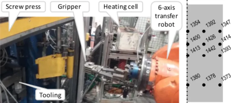
Gripper Heating cell 6-axis transfer
robot Screw press
Tooling
Figure 3. Robotized cell and induction heating furnace with controlled
atmosphere at LCFC (left) and measured temperature field (in °C) at the end of induction heating (right).
Numerical simulations with the physically-based micro-mechanical model developed by Favier et al [14][15] predicts that the scatter in solid skin thickness is less than 30%. It is important to remind that the liquid fraction is difficult to measure directly for most steel grades, so that it must be determined indirectly. DTA calculations must be validated and optimized by direct experimental measurements of liquid fraction using steel grades with alloying elements that create natural markers of the liquid phase after quenching (for example, M2 steel, as shown in Figure 4). In this way, the liquid fraction at the end of the heating / transfer cycle could be determined with good accuracy. The impact of the remaining process variability with this alternative SSF approach is investigated in the next section.
a
b
c
Figure 4. A posteriori liquid fraction determination by various methods
on M2 steel: a) optical microscopy (after quenching), b) confocal laser scanning microscopy and c) 3D reconstruction of liquid zone and solid skeleton by X-ray tomography [16].
3. Laboratory proof of concept
The SSF process was implemented on a laboratory forging cell including the furnace described in Section 2, a SPR400 Lasco screw press of 31.5kJ and 680mm/s maximum forging speed, and
a 6-axis transfer robot with specific gripper for the feedstock transfer. Forging tools of industrial scale can be housed in the press’ work volume of 710710940mm3.
A backward extrusion laboratory part was designed to investigate the robustness of the proposed route for steel SSF. The tool and part are shown in Figure 5. The part material is C38LTT steel. Different cross-section reduction ratios can be obtained by changing the thickness of the drawn wall. A typical part obtained by the proposed SSF process is shown in Figure 6. The clear traces of rolling fibres at the bottom of the part testifies that during the inductive heating phase, partial remelting occurred mainly at the core of the billet. The heavily sheared area corresponds to the semi-solid core.
H h Ø e D h 25 D 49 e 5 7 Ø 39 35 H 95 77 Dimensions in mm
Figure 5. Tool designed for semi-solid steel forging, and laboratory part.
Ferrite (white)
Pearlite (gray)
Figure 6. Part analysis after semi-solid forging with the proposed
approach.
Parts were forged using different heating cycles in order to explore the process limits. As commonly recommended in the literature, the heating process included two successive steps: a first step at high heating power for the rapid temperature increase and a second step at lower heating power for the final temperature increase while allowing for the expected temperature distribution within the part. Different temperature distributions were obtained by controlling the heating time during the first heating step. Transfer time was kept constant for all configurations.
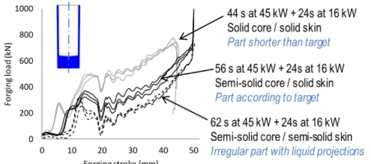
Figure 7 shows that for each heating conditions the forging force as well as the final part geometry were repeatable. A significant decrease of the forging force was recorded when the aimed semi-solid core was created. Increasing the heating time led to an increase of the average liquid fraction and a decrease of the solid skin thickness, which eventually led to liquid ejections due to flow segregation. It is noteworthy that for such a flashless open-surface part geometry, liquid ejection leads to part rejection and should be avoided. According to the results in Figure 7, the increment in force reduction between the optimized SSF conditions and the conditions that led to liquid ejection was relatively small, showing that most of the benefits of SSF are already reached with the optimized conditions.
0 200 400 600 800 1000 -20 -10 0 10 20 30 Fo rg in g lo ad (kN ) Forging stroke (mm) 0 10 20 30 40 50 44 s at 45 kW + 24s at 16 kW Solid core / solid skin
Part shorter than target
56 s at 45 kW + 24s at 16 kW Semi-solid core / solid skin
Part according to target
62 s at 45 kW + 24s at 16 kW Semi-solid core / semi-solid skin
Irregular part with liquid projections
Figure 7. Force-stroke plots for one part geometry and three different
part heating cycles.
The robustness and repeatability of the process was also investigated and observed for a second part geometry with a different thickness of the extruded wall, as shown in Table 1. Several parts were forged for each geometry using the same heating and transfer cycle. Consequently, the laboratory trials showed that the process was repeatable and its benefits could be measured in terms of load reduction and improved metal flow as compared to hot forging.
Geometry Maximum load [kN] 519 566 516 536 223 229 225 206 Average [kN] Mean deviation [kN] Maximum deviation [kN] 67 Thickness e = 5 mm 527 19 45 Thickness e = 7 mm 213 15
Table 1. Semi-solid maximum forging force repeatability for two different
values of the extruded wall thickness.
4. Validation in industrial environment
One of the major expected benefits from the proposed approach is the ability to use the same tool materials for SSF as for hot forging without facing the drastic tool degradation due to the contact with liquid steel. In order to investigate the tool lifetime in the most representative conditions, trial runs were organized at an industrial forging plant, in the framework of the Thixofranc partnership.
A typical part was designed in agreement with several forging companies, in order to combine in one part the most difficult forging geometries. Near-net geometries are aimed by elimination of the flash and small extrusion angles. The part shown in Figure 8 exhibits backward extrusion with wall angles of 2.5°, forward extrusion with wall angle of 1°, and four lateral extrusion arms with 0° angle in the material flow direction. The part material is C38LTT. A single press stroke was considered in the designed forging process. According to the industrial consortium, this part is considered unfeasible in a single stroke by hot forging.
740 g
Figure 8. Semi-industrial demonstrator part – geometry and initial
microstructure [6].
The forging cell used an industrial automatic mechanical press with capacity of 25,000 kN. A specific heating unit was designed that comprised 28 inductive heating cells, for a whole set up
power of 600kW. The target temperature of 1430°C could be obtained in 160 seconds. Preliminary inspection by thermocouples revealed that the stabilized temperature was repeatedly measured within a scatter range of 7°C. The heating was operated under neutral atmosphere to avoid scale formation. The closed forging dies were produced from X38CrMoV5, classical steel for hot forging tools.
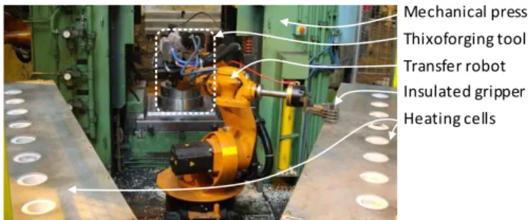
The billet transfer from the different heating cells to the lower die of the tool was ensured by a programmed robot. With these 16 cells and the transfer robot, production rates up to 450 parts per hour could be reached. The forging cell used for this experiment is shown in Figure 9. Further details on the heating procedure of the parts and tools can be found in [13].
Mechanical press Thixoforging tool Transfer robot Insulated gripper Heating cells
Figure 9. Semi-solid steel forging demonstrator setup in industrial plant.
Preliminary trials were performed to validate the transfer and the temperature at the exit of the heating cells. Subsequently, a batch of 3500 parts was produced over three successive days with the same tool. The average production rate was of ten parts per minute during the stabilized production periods.
In these conditions, the tools could reach the thermal steady state typical for industrial use and the tool wear could be investigated beyond the running-in period, during which the tool wear is known to progress rapidly over a limited period. The tool wear during the process could not be measured directly in these conditions of continuous production, but instead it was traced by measuring the part geometry evolution. For this, the part geometry was measured on 75 parts representative of the entire batch. As shown in Figure 10, the part geometry was very close to the nominal values, with an evolution due to tools wear equivalent to hot forging conditions.
The maximum load measured for the SSF process was 450kN, for a part of 740g. The analyzed parts were porosity-free, with correct material flow.
0 5 10 15 20 25 -0,6 -0,4 -0,2 0 N umb er o f me as ur eme d pa rts Angle error [°] Backward drawing outer Backward drawing inner Forward drawing 0 10 20 30 40 50 60 70 0 1 2 3 N umb er o f me as ur ed p ar ts Straightness error Arm A Arm B Arm C Arm D 0 10 20 30 40 50 60 70 0 1 2 3 Nu mb er o f me as ur ed p ar ts Straightness error Arm A Arm B Arm C Arm D Arm A Arm B Arm D Arm C
a
b
[mm]Figure 10. Geometry measurements of 75 representative SSF forged
parts: a) Error of the extrusion angles and b) straightness error of the four laterally-extruded arms.
5. Conclusions
The approach proposed in this paper aims to solve two of the main difficulties of semi-solid forming of steels: the lifetime of
tools and the part quality in connection to flow segregation. Both are related to the presence of significant liquid fraction at the surface of the part. As a consequence, the envisioned solution was to confine the semi-solid material within a solid skin, by adequately monitoring the heating and transfer steps. Controlled and repeatable thermal conditions were obtained and validated experimentally. According to the laboratory trials, the proposed process is able to deliver parts with good quality in a repeatable way, with a significant reduction of the forging force as compared to classical hot forging. In the mean time, trials on industrial equipment showed that the tool wear is equivalent to what is classically observed in hot forging, with no significant deterioration. According to these results, the solid skin effect can be purposely used for process control, leading to improved robustness and opening the way to the industrialization of SSF for steels. Indeed, successful SSF trials could be performed at industrial production rates.
Acknowledgements
The authors are grateful to Olivier Gyss, Florian Baratto, Fanny Diller, Damien Noizillier and Jean-Baptiste Croué for their contribution to the experiments. The reported work has been supported by Région Lorraine and Région Champagne Ardennes through the Thixofranc project, by the IRT M2P through the TACA project, and by ISEETECH through the forging equipment. References
[1] Kiuchi, M., Yanagimoto, J., Yokobayashi, H., 2001, Flow stress, yield criterion and constitutive equation of mushy / semi-solid alloys, Annals of the CIRP, 50/1:157-160.
[2] Kiuchi, M., Kopp, R., 2002, Mushy / Semi-solid metal forming technology – present and future, Annals of the CIRP, 51/2:653-670.
[3] Hirt, G., Shimahara, H., Seidl, I., Küthe, F., Abel, D., Schönbohm, A., 2005, Semi-solid forging of 100Cr6 and X210CrW12 steel, Annals of the CIRP, 54/1:257-260. [4] Telle, R., Muenstermann, S., Beyer, C., 2006, Design, construction and
performance of silicon nitride tool parts in steel thixoforming, Solid State Phenomena, 116-117:690–695.
[5] Rassili, A., Pierret, J.C., Vaneetveld, G., Halleux, J., Walmag, G., Lecomte-Beckers, J., 2010, X38CrMoV5 hot-work tool steel as tool material for thixoforging of steel: Numerical and experimental evaluation, Transactions of Nonferrous Metals Society of China, 20:s713–s718.
[6] Bigot, R., Becker, E., Langlois, L., 2012, Some approaches on industrialization of steel thixoforging processes, Proceedings 12th Int. Conf. Semi-Solid Processing of Alloys and Composites, Oct 2012, Cape Town, South Africa, 521-526. [7] Lozares, J., Azpilgain, Z., Hurtado, I., Ortubay, R., Berrocal, S., 2012, Thixo
Lateral Forging of a Commercial Automotive Spindle from LTT45 Steel Grade, Key Engineering Materials, 504–506:357–360.
[8] Meng, Y., Sugiyama, S., Yanagimoto, J., 2012, Microstructural evolution during RAP process and deformation behavior of semi-solid SKD61 tool steel, Journal of Materials Processing Technology 212:1731–1741.
[9] Valette-Brives, E., 1992, Mise en forme d’aciers à l’état semi-solide : étude expérimentale et modélisation (in French), PhD Thesis, Mines Paris, France. [10] Kopp, R., Kallweit, J., Möller, T., Seidl, I., 2002, Forming and joining of
commercial steel grades in the semi-solid state, Journal of Materials Processing Technology 130–131:562–568.
[11] Kapranos, P., Kirkwood, D.H., Sellars, C.M., 1996, Thixoforming high melting point alloys into non-mettallic dies, Proceedings of 4th Int. Conf. Semi-Solid Process. Alloy. Compos., 1996, Sheffield, England.
[12] Püttgen, W., Bleck, W., Hirt, G., Shimahara, H., 2007, Thixoforming of steels - A status report, Advanced Engineering Materials, 9/4:231-245.
[13] Becker, E., Favier, V., Bigot, R., Cézard, P., Langlois, L., 2010, Impact of experimental conditions on material response during forming of steel in semi-solid state, Journal of Materials Processing Technology, 210/11:1482-1492. [14] Favier, V., Cézard, P., Bigot, R., 2009, Transient and non-isothermal semi-solid
behaviour: 3D micromechanical modeling, Materials Science and Engineering A, 517/1-2:8-16.
[15] Neag, A., Favier, V., Bigot, R., Atkinson, H.V., 2012, Microstructure and flow behaviour during backward extrusion of semi-solid 7075 aluminium alloy, Journal of Materials Processing Technology, 212/7:1472-1480.
[16] Gu, G.C., Pesci, R., Langlois, L., Becker, E., Bigot, R., Guo, M.X., 2014, Microstructure observation and quantification of the liquid fraction of M2 steel grade in the semi-solid state, combining confocal laser scanning microscopy and X-ray microtomography, Acta Materialia, 66:118-131.