Science Arts & Métiers (SAM)
is an open access repository that collects the work of Arts et Métiers Institute of Technology researchers and makes it freely available over the web where possible.
This is an author-deposited version published in: https://sam.ensam.eu Handle ID: .http://hdl.handle.net/10985/17324
To cite this version :
Alexander NIKITIN, Claude BATHIAS, Thierry PALIN-LUC, Andrey SHANYAVSKIY - Crack path in aeronautical titanium alloy under ultrasonic torsion loading Frattura ed Integrità Strutturale -Vol. 10, n°35, p.213-222 - 2015
Any correspondence concerning this service should be sent to the repository Administrator : [email protected]
A. Nikitin et alii, Frattura ed Integrità Strutturale, 35 (2016) 213-222; DOI: 10.3221/IGF-ESIS.35.25
213
Focussed on Crack Paths
Crack path in aeronautical titanium alloy under ultrasonic torsion
loading
A. Nikitin, C.Bathias
LEME, University Paris Ouest Nanterre La Defense, 50, rue de Serves, Ville-d'Avray, 92410, France [email protected]
T.Palin-Luc
Arts et Metiers Paris Tech, I2M, CNRS University of Bordeaux, Esplanade des Arts et Metiers, Talence, 33405, France [email protected]
A. Shanyavskiy
SCCAFS, Air. Sheremetevo-1, PO Box 54, Moscow reg., Chimkovskiy state, 141426, Russia [email protected]
ABSTRACT. This paper discusses features of fatigue crack initiation and growth in aeronautical VT3-1 titanium
alloy under pure torsion loading in gigacycle regime. Two materials: extruded and forged VT3-1 titanium alloys
were studied. Torsion fatigue tests were performed up to fatigue life of 109 cycles. The results of the torsion
tests were compared with previously obtained results under fully reversed axial loading on the same alloys. It has been shown that independently on production process as surface as well subsurface crack initiation may appear under ultrasonic torsion loading despite the maximum stress amplitude located at the specimen surface. In the case of surface crack initiation, a scenario of crack initiation and growth is similar to HCF regime except an additional possibility for internal crack branching. In the case of subsurface crack, the initiation site is located below the specimen surface (about 200 µm) and is not clearly related to any material flaw. Internal crack initiation is produced by shear stress in maximum shear plane and early crack growth is in Mode II. Crack branching is limited in the case of internal crack initiation compared to surface one. A typical ‘fish-eye’ crack can be observed at the torsion fracture surface, but mechanism of crack initiation seems not to be the same than under axial fatigue loading.
KEYWORDS. Very-High Cycle Fatigue; Titanium alloy; Torsion; Ultrasonic; Crack initiation; Crack growth.
INTRODUCTION
t was outlined by many authors that study on fatigue properties of structural materials, such as steels, aluminum and titanium alloys, under torsion loading is an important subject for industrial applications [1-2]. Many engineering elements are subjected to complex loading involving bending, tension or torsion load modes. Moreover, in case of modern applications, such as cars, high-speed trains and aircraft motors, a significant fatigue life for components can be
I
A. Nikitin et alii, Frattura ed Integrità Strutturale, 35 (2016) 213-222; DOI: 10.3221/IGF-ESIS.35.25
214
achieved during in-service due to high loading rate [3]. Analysis of in-service loads for aeronautical applications [4] has shown that fatigue life of compressor blades may reach more than 109 cycles that is in the very-high cycle fatigue regime. Since the beginning of the 1990th, this fatigue regime is under investigations [5]. Mainly the VHCF properties of structural materials were investigated under axial push-pull loading, but some different testing systems were developed to reproduce different in-service loading and conditions [6]. In the recent years, investigations on fatigue properties of metals under torsion loading become more and more actual topic [7, 8].
Results of ultrasonic tests on high-strength aluminum shows that torsion fatigue crack in VHCF regime have a qualitative similarity to crack in HCF regime [9]. It has been shown that crack initiation under torsion is located at the surface of specimen. The first stage of growth is found in the plane of maximum shear stress with further formation of circumferential crack. However, a few years after, it has been shown that under torsion loading in VHCF range as surface, as well a subsurface cracks may also appears if material contains a non-metallic inclusions. In reference [10] high-strength steel was studied up to a fatigue life of 109 cycles. In the case of surface initiation, the fracture surface of 100C6 steel shows a similar to HCF 'factory roof' pattern, but in the case of subsurface crack initiation, an initiation mechanism is more similar to push-pull fatigue. In this case a 'fish-eye' pattern is formed around an elongated non-metallic inclusion, fig.1b. The torsion fatigue crack does not show a significant branching and 'factory roof' fracture is absent, fig.1a. Unlike high-strength aluminum, a 38MnSV5S steels shows a surface crack initiation on the plane of maximum normal stress (45° by the specimen's axis) [11] and further propagation in inclined (by the specimen's length) plane with tendency to turn back to the maximum shear stress plane.
(a) (b)
Figure 1: Subsurface fatigue crack initiation in 100C6 steel under ultrasonic torsion, shear stress is 360 MPa, Nf is 109 cycles [10].
Ultrasonic torsion VHCF data on titanium alloy are not available in the literature. The study of Ti-alloys under torsion loading in VHCF regime is a very interesting subject, because titanium is defect free metal which has a quite complex micro-structure that may produce internal crack initiation, like shown under push-pull fatigue [12]. Present paper is focused on the study of crack initiation mechanisms in aeronautic titanium alloy VT3-1 under ultrasonic torsion in VHCF
(106 – 109 cycles). Two main questions are discussed: (1) does a VHCF torsion loading may produce and internal crack
initiation in VT3-1 titanium alloy; (2) does fatigue crack initiation an early crack growth stage in VT3-1 under torsion loading will be similar to ones that were observed under push-pull loading.
EXPERIMENTAL PROCEDURE
Materials
aterial for present investigation is two phase titanium alloy VT3-1 (similar to Ti-6Al-4V) which is commonly used in aircraft engine industry. Its chemical composition is presented in Tab. 1.
Two sets of specimens were used for present investigation. The first set was machined from a real compressor disk of Tu-154 aircraft. This disk was produced by forging technology for D30 engine. This compressor disk was in service for 6000 flight cycles (takeoff – landing). An estimate in service time is about 18000 hours. After in-service the disk was checked for damage tracks by non-destructive control methods. This analysis did not show any fatigue damage due to in-service loading and the disk was transmitted to fatigue tests.
A. Nikitin et alii, Frattura ed Integrità Strutturale, 35 (2016) 213-222; DOI: 10.3221/IGF-ESIS.35.25
215
Fe C Si Cr Mo N Al Zr O H Titanium
0.2 - 07 0.1 < 0.15 – 0.4 0.8 - 2 2 - 3 < 0.05 5.5 - 7 < 0.5 0.15 < 0.015 < Balance
Table 1: Chemical composition of VT3-1 titanium alloy, weight %.
The second set of specimens was machined from virgin extruded bars, produced by All Russian Institution of Light Alloys with respect to state standards [13]. Heat treatment was performed to get a fully lamellar micro-structure and mechanical properties close to forged VT3-1.
Mechanical properties of both materials were obtained on tensile specimens of 75 mm in length under displacement rate of 0.075 mm/min. The result of tensile test and obtained mechanical properties are listed in Tab 2.
Process Young's modulus, GPa UTS, MPa Yield Stress, MPa Deformation at rupture, % density Mass Young's modulus Dynamic (GPa)
Forged 114 989 960 6 4500 116
Extruded 106 1107 1050 13 4500 110
Table 2: Mechanical properties of forged and extruded VT3-1 titanium alloys
The extruded titanium alloy has mechanical properties a little bit higher than the forged one, except its elongation at rupture that is significantly different. It is more than two times higher for extruded titanium that is, therefore, more
ductile. Furthermore their micro-hardness is approximately the same: 364 HV500 for forged and 373 VH500 for extruded
VT3-1. Measurement was realized in the plane of maximum shear stress of specimens along a line through a cross-section
of the specimen. Results shows a pronounced scatter for the forged titanium alloy (the difference of 44 HV500 was found
for points spaced by 1.2 mm), while for extruded VT3-1 it is less than 5 HV500 for the same distance. Such difference may be explained by features of micro-structures for these alloys.
The 3D mapping of the micro-structure is shown on Fig. 2 for forged and extruded alloys.
(a) (b) Figure 2: The 3D mapping of micro-structure for (a) forged and (b) extruded VT3-1.
Both alloys have fully lamellar micro-structure with elongated alpha-platelets. In the case of forged VT3-1 platelet size is larger (about 2 µm in width and 10-15 µm in length), while w = 1 µm by l = 2-3 µm for the extruded one. Moreover, micro-structure of extruded titanium alloy is more homogeneous (except some zones in the core of the bar), while the micro-structure of forged titanium is processed in macroscopically large zones with similar platelets morphology. These zones called 'macro-zones' [14] and characterized by similar crystallographic orientations of the platelets within each macro-zone. The existence of such specific of micro-structure explains the large scatter obtained in micro-hardness values for forged VT3-1.
A. Nikitin et alii, Frattura ed Integrità Strutturale, 35 (2016) 213-222; DOI: 10.3221/IGF-ESIS.35.25
216
Experimental method
Torsion fatigue tests were performed on specimens, designed according to ultrasonic concept applied to torsion [3, 14] and taking into an account dynamic elastic properties of materials at 20 kHz (Tab.2). Specimens made of forged VT3-1 were cut from the rim part of compressor disk along an axis of disk symmetry. Specimens made of extruded VT3-1 were machined from bar so that specimen's longitudinal axis is the same than extrusion direction. Geometry of ultrasonic torsion specimens is presented on Fig.3a. Working section of specimen was polished by emery papers from grade 600 to 1000. Fatigue tests were performed continuously (without pulse - pause) by using a self-designed ultrasonic torsion system [14], (Fig.3b) up to fatigue failure or run out limit of 109 cycles. All the tests were performed at room temperature with permanent compressed dry-air cooling. An infrared camera was used for monitoring surface temperature of specimen during fatigue tests. Result shows that there is now significant self-heating effect in VT3-1 titanium alloy under torsion loads [15].
(a) (b)
Figure 3: (a) Geometry of ultrasonic torsion specimen and (b) ultrasonic torsion testing system.
The calibration of the testing system was performed with strain gauge and Vishay conditioning device with a large bandwidth (up to 100 kHz). Calibration shows a perfect linear relation between applied tension and measured deformation.
The fatigue crack under torsion is detected by drop of resonance frequency. This crack detection is done automatically with a high-performance computer feet-back controller. After each test the crack existence is verified by optical microscope.
When the crack is detected, a specimen was subjected to self-designed method of specimen opening. As was discussed above, titanium alloy is ductile material and an important plastic deformation may leads to destruction of fracture surface during direct opening. In order to minimize these risks a 'life section' of specimens is reduced by electro-erosion cut. A fill is placed beside a fatigue crack so that surface crack tips are placed on the same line with a wire (in present case it is inclined 45° with respect the specimen longitudinal axis). After reducing the ‘life section’, the specimen is cooled by liquid nitrogen and subjected to sharp shock, so that provide fatigue crack opening.
After opening, all the cracked specimens were analysed by using scanning electron microscopy (SEM). An additional attention has been paid to the crack initiation mechanisms.
RESULTS
SN-curves for forged and extruded Ti-alloys
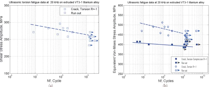
he results of fatigue tests on both forged (Fig.4a) and extruded (Fig.5a) titanium alloy shows that fatigue failure under pure torsion loading may occur well beyond 106 cycles. In spite of limited fatigue data on forged VT3-1 it is possible to plot a curve fitting the results. This curve will have an important slope in the VHCF range. Decreasing in fatigue strength with increasing number of loading cycles is more pronounced for torsion mode compared to results of axial tension-compressing tests [16] that is presented on Fig.4b. In order to compare the results of torsion and axial tests, the following equation was used to recalculate the shear stress amplitude into equivalent (Von Mises) normal stress
A. Nikitin et alii, Frattura ed Integrità Strutturale, 35 (2016) 213-222; DOI: 10.3221/IGF-ESIS.35.25
217 3
. It can be pointed out that points plotted in equivalent stress terms for forged VT3-1 show a good agreement
and grouped near to 400 MPa that is about 40 % of UTS. This result is similar to typical results on titanium alloys in the HCF range.
(a) (b)
Figure 4: Results of fatigue tests on forged VT3-1 titanium alloy (a) torsion data in terms of shear stress amplitude and (b) tension compression R=-1 and torsion data in terms of equivalent normal stress amplitude.
The torsion results cover a range of fatigue life from about 106 to 108 cycles. Based on previous results obtained on forged VT3-1 under fully reversed tension loading, the crack initiation mechanisms could be quite different at such fatigue life for forged alloy [16]. Besides a changing from surface to subsurface crack initiation mode, it has been reported about micro-structural fatigue life controlling mechanisms. In the case of torsion loading, a transition from surface to subsurface initiation after longer fatigue life was also found. However, this transition appears at fatigue life of about two order of magnitude longer. Detailed analysis on fatigue crack initiation mechanisms under torsion loading will be provided in the section ‘Discussion’.
(a) (b)
Figure 5: Results of fatigue tests on extruded VT3-1 titanium alloy (a) torsion data in terms of shear stress amplitude and (b) tension compression R=-1 and torsion data in terms of Von Mises equivalent stress amplitude.
Like for the forged alloy, the SN curve in torsion for the extruded VT3-1 titanium alloy exhibits a significant slope in
VHCF regime, Fig.5a. Since the fatigue tests were stopped around 109 cycles, most of the cracks were observed in the
A. Nikitin et alii, Frattura ed Integrità Strutturale, 35 (2016) 213-222; DOI: 10.3221/IGF-ESIS.35.25
218
titanium alloy were compared with previous results [17] obtained on the material but under fully reversed tension, Fig. 5b.
In terms of Von Misesequivalent stress amplitude, like for the forged alloy, the slope of the SN-curve is more important
under torsion than under tension-compression. However, unlike the forged alloy, fatigue strength of extruded titanium is higher (about 50 MPa) in torsion than in tension-compression. This shows that the Von Mises equivalent stress is not suitable to describe the VHCF strength of this alloy. In order to try to explain such mechanical behavior the analysis of the fracture surface was carried out both by optical microscopy and SEM. Unlike tension-compression, where only subsurface crack were observed, in case of torsion load a transition from surface to subsurface crack initiation was found. Comparison of results on forged and extruded titanium alloy (Fig.4 and Fig.5) shows that fatigue strength of extruded titanium alloy is higher compared to the forged one that is in good agreement with mechanical properties of materials (Tab.2).
Crack initiation
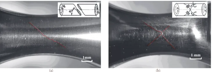
Cracks in torsion specimens were first observed on a lateral surface of specimens by optical microscopy. It was pointed out, that for most of the investigated specimens the first stage of crack propagation was observed on a plane experiencing the maximum shear stress amplitude i.e. perpendicular or parallel to the specimen’s longitudinal axis. Further, when the crack became longer it bifurcated (Stage II) and propagated in Mode I on plane(s) of maximum normal stress (i.e. on plane having an angle about 45° with regard to the specimen’s longitudinal axis). The propagation of long crack was never observed in the plane of maximum shear stress amplitude up to the final length (corresponding to the end of the test). It should be noted, that crack growth in the plane of maximum normal stress may be found as in a single plane, as well in two planes at the same time (X-type cracks), Fig.6b. This is similar to HCF regime on many metals.
(a) (b)
Figure 6: Optical microscopy at the surface of torsion specimens: (a) single crack in the plane of maximum normal stress and (b) two cracks in two 45° orientated planes of maximum normal stress or X-type crack.
Crack growth under torsion loading in the plane of maximum normal stress looks to be quite sensitive to material microstructure. Comparing the surface crack path of extruded and forged titanium alloy it is notable, that branching of the crack is higher for forged titanium alloy represented by less homogenous microstructure. An example of crack path in extruded titanium alloy is showing on the Fig.6a. In this case the crack is quite well orientated on the 45° plane, while in case of forged titanium alloy, Fig.6b, the crack path is more ‘zigzag’ (alternative branching mode I and mode II). Sometimes crack make a clear ‘steps’ or even sometimes it is propagating in a two parallel 45° planes.
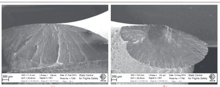
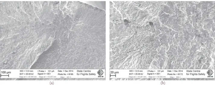
An observation on a fracture surface of torsion specimens (after opening) shows two types of crack for both alloys: (1) surface crack and (2) subsurface crack. In the case of extruded VT3-1 these two mechanisms are more clear, Fig.7
In the case of surface crack initiation the roughness of the fracture surface is lower. That can be concluded based on a more homogeneous color. In the case of subsurface crack initiation, a roughness of fracture surface in the area of subsurface and surface crack propagation is not the same, that clearly seen by pronounceable color change. Subsurface crack initiation under torsion loading leads to forming a well known (in pull) ‘fish eye’ pattern [3]. But unlike push-pull loading, torsion cyclic loading produced an oval ‘fish-eye’
A. Nikitin et alii, Frattura ed Integrità Strutturale, 35 (2016) 213-222; DOI: 10.3221/IGF-ESIS.35.25
219
(a) (b)
Figure 7: Surface (a) and subsurface ‘fish-eye’ (b) crack initiations in extruded VT3-1 titanium alloy under torsion loading. The next difference between torsion and pull-push ‘fish-eye’ is the nature of smooth area. In the case of axial loading, the formation of such area is governed by crack growth rate, while in the case of torsion ‘fish-eye’ a second factor can be stated. Indeed the smooth area of torsion crack is limited by an ellipse, that ‘touches’ the specimen surface. More rough fracture surface is starting to form when an internal crack reaches the specimen surface. Probably, there are several factors acting together and leading to fracture roughness modification. One can say: (1) the crack growth rate increasing when the crack reaches the specimen surface; (2) presence of environment (gasses) into the crack, when it connects to the surface. Anyway, a smooth area of torsion ‘fish-eye’ exists till an internal crack turns to a surface crack. The next pronounceable difference between surface and subsurface initiation is less expressed branching of internal crack. On Fig.7a several clear traces can be observed. These traces are formed due to crack propagation in series of parallel planes, orientated at 45° with regard to the specimen longitudinal axis. In the case of subsurface crack initiation, growth of several cracks in 45° planes is also possible, but this is well limited. It is interesting to point out, that in the case of high strength steel, Fig.1a [10], a fracture surface with internal crack initiation does not show a significant branching pattern (no 45° ‘wings’ ).
DISCUSSIONS
irst of all, the comparison of SN-curves for push-pull and torsion loadings (Fig.4 and 5) shows a more important slope of SN-curve in the case of torsion loading. This tendency keeps being the same as for forged, as well for extruded titanium alloy in spite of small difference of SN-curves for these alloys under push-pull fatigue. This means that VT3-1 titanium is more sensitive to shear stress than to normal one. This is typical for ductile metals. However, long crack propagation is observed in planes of maximum normal stress which is typical for more brittle material. Therefore, at the very first stage of fatigue crack initiation, when a crack length is about the same order than the grain size the fatigue behavior of titanium is similar to ductile material and fatigue damage accumulation is due to sliding
process. In the case of two-phase titanium alloy a higher capacity to accommodate plastic sliding has a hexagonal
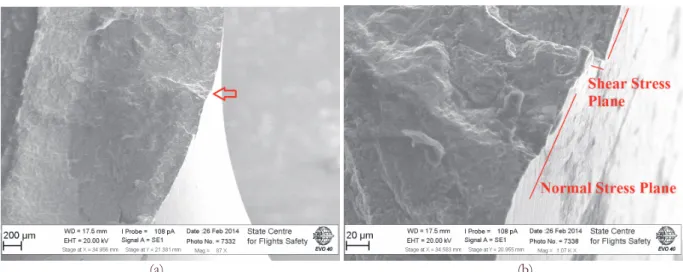
alpha-phase. Thus, the fatigue resistance of titanium alloy to torsion loading may be related to features of alpha-platelets. In the case of surface torsion crack it can be observed macroscopically at surface in one of two maximum shear stress planes: along or perpendicularly to specimen’s axis. Fig.8b shows an example of first torsion crack growth stage along an axis.
When torsion crack reaches a length of several micrometers, the crack growth turns into a plane of maximum normal stress, Fig. 8b. Typical size of platelets is very small for the studied titanium alloys and micro-plasticity of alpha-phase is not enough to accumulate fatigue damage at later stage of crack growth that turns fatigue behavior of material to the brittle-mode failure (governed by the normal stress cracking mechanisms). Another reason that can limit the stage of crack growth in shear plane is quite high deformation rate in the case of ultrasonic loading. But anyway, a transition from maximum shear to normal stress plane is typical for torsion cracking at different loading frequencies. In reference [18] fully reversed torsion fatigue tests were carried out on titanium alloy Ti-6Al-4V in HCF regime at a loading frequency of
F
A. Nikitin et alii, Frattura ed Integrità Strutturale, 35 (2016) 213-222; DOI: 10.3221/IGF-ESIS.35.25
220
10 Hz. The authors also observed a surface crack along the specimen’s axis which reached a length of about 700 µm in maximum shear stress plane before bifurcation onto the maximum normal stress plane.
(a) (b)
Figure 8: Surface crack initiation in forged VT3-1 under torsion loading (a) overview of torsion crack with initiation site marked by arrow and (b) detailed crack initiation view.
The microstructure of TiA6V titanium alloy [18] is globular and coarse that is different from present Ti-6Al-4Mo titanium alloy microstructure. Thus, it is difficult to distinguish the role of microstructure and loading frequency on duration of crack growth in shear plane, but it is clear, that this growth stage should be limited by the material capability to accumulate plastic deformation. It has been shown that in the case of HCF a torsion crack first growth in depth of material and after starts to branch at the surface without growing in depth [18]. In the present work on VT3-1 titanium alloy crack tip position versus number of cycles was not monitored and crack shape was reconstructed based on the fracture surface pattern.
In the case of surface crack initiation a sort of crack branching threshold or critical crack length was found, Fig.9. It seems that at a certain crack length internal crack branching is also possible in the case of VHCF loading that is different from HCF. A slight difference in the fracture surface color in zones before and after branching is due to different roughness that is usually associated with difference in stress intensity factors or crack growth rate.
(a) (b)
Figure 9: Fracture surfaces of specimens (a) S=; Nf= (b) S=; Nf=; with clear border of fatigue crack branching.
Unfortunately, a reconstruction of the very first stage of torsion crack growth based on fracture pattern is problematic due to destruction of the fracture surface near the initiation site by friction between crack lips during Mode II stage. Finally, a surface torsion crack in VHCF is similar to HCF growth i.e. it initiates on the maximum shear stress plane and
A. Nikitin et alii, Frattura ed Integrità Strutturale, 35 (2016) 213-222; DOI: 10.3221/IGF-ESIS.35.25
221 growth in Mode II at the very first stage, but a crack growth bifurcation mechanism seems different for HCF and VHCF. In the case of VHCF branching can be observed in the bulk of material, while in HCF it appears at the surface [18] Such difference in the branching mechanism may have the same nature with one more interesting feature of VHCF torsion behavior. That is an internal crack initiation under VHCF torsion loading in spite of maximum shear stress located at the surface. An analysis of internal crack initiation site in VT3-1 titanium alloy did not show any structural flaw in the microstructure so that inclusions or clusters of alpha-platelets, Fig. 10. The crack initiation site is significantly destroyed by friction that is clearly seen in Fig.10b. A ‘step’ at the fracture surface and followed crack growth in two parallel planes means that internal crack is also initiated in the plane of maximum shear stress. After reaching a certain length (that is shorter than the distance from initiation site to surface) the crack branches on the plane of maximum normal stress. Sometimes there is a sort of competition between two maximum normal stress planes that produce a ‘wing’ like structure at the surface. Excluding this ‘wing’-like structures, a further branching is limited in the case of internal crack initiation and no branching ‘threshold’ (like in case of surface crack) can be found at the fracture surface. In contrary, another notable zone or critical crack length can be reported. As shown in Fig.7b the crack front shape is changing as soon as it arrives at the surface, probably because the stress intensity factor is increasing and consequently the crack growth rate too.
(a) (b)
Figure 10: Fracture surfaces of specimens (a) S=; Nf= (b) S=; Nf=; with clear border of fatigue crack branching.
Finally, for forged titanium alloy loaded under push-pull fatigue crack initiations were mainly associated with macro-zones and smooth facets cracking [16], while in the case of torsion loading these features were not found.
CONCLUSIONS
ased on the results of fatigue tests under pure ultrasonic torsion the next conclusions can be drawn up:
(1) SN curves of VT3-1 titanium alloy under torsion R=-1 loading have a more significant slope, compared to results under fully revered tension. However, the relation between axial and torsion fatigue strength obtained for HCF seems to be applicable for VHCF data.
(2) Independently on the production process (forging and extrusion) two different crack initiation sites were found:
surface and subsurface crack. The subsurface crack initiations were observed for specimens failed at longer fatigue life. Transition from surface to subsurface crack initiation was found well after the same transition for push-pull loading: about 108 cycles for torsion and 106 cycles for axial loading.
(3) Qualitatively, a surface cracking under torsion loading in VHCF is similar to HCF results, except an additional possibility for internal crack to branch in VHCF regime.
(4) A sort of branching ‘threshold’ or critical crack length can be found at the fracture surface, beyond which a torsion crack shows several branches in another 45° plane of maximum normal stress.
(5) In the case of internal crack, an initiation and early crack growth is also being in Mode II. Bifurcation to a normal stress plane growth happens before the crack reaches the specimen’s surface. Further crack growth is processed along the specimen surface. At later stage of subsurface growing a crack turns to the surface. The moment when subsurface
A. Nikitin et alii, Frattura ed Integrità Strutturale, 35 (2016) 213-222; DOI: 10.3221/IGF-ESIS.35.25
222
crack reaches a surface is clearly defined by different fracture morphology that is similar to well known ‘fish-eye’ crack.
REFERENCES
[1] Shimamura, Y., Narita, K., Ishii, H., Tohgo, K., Fujii, T., Yagasaki, T., Harada, M., Fatigue properties of carburized alloy steel in very high cycle regime under torsional loading, Int.J. of Fatigue, 60 (2014) 57-62.
DOI: 10.1016/j.ijfatigue 2013.06.016.
[2] Tschegg, E.K., Stanzl-Tschegg, S.E., Mayer, H.R., High frequency method for torsion fatigue testing. Ultrasonics, 31(4) (1993) 275 - 280.
[3] Bathias, C., Paris, P.C., Gigacycle Fatigue in Mechanical Practice, Dekker, New York, 2004, ISBN-10: 0824723139. [4] Nicholas, T., Critical issues in high cycle fatigue, Int. J. of Fatigue, 21 (1999) S221-S231. DOI:
10.1016/S0142-1123(99)00074-2.
[5] Sakai, T., Review and Prospects for Current Studies on Very High Cycle Fatigue of Metallic Materials for Machine Structural Use, J.Solid Mechanics and Material Engineering, 3(3) (2009) 425-439. DOI: 10.1299/jmmp.3.425.
[6] Bathias, C., Piezoelectric fatigue testing machines and devices, Int. J. of Fatigue, 28(11) (2006) 1438-1445. DOI: 10.1016/j.ijfatigue.2005.09.020.
[7] Mayer, H., Schuller, R., Karr, U., Irrasch, D., Fitzka, M., Hahn, M., Bacher-Hochst, M., Cyclic torsion very high cycle fatigue of VDSiCr spring steel at different load ratios, 70 (2015) 322-327. DOI: 10.1016/j.ijfatigue.2014.10.007. [8] Ishii, H., Tohgo, K., Fujii, T., Yagasaki, T., Harada, M., Shimamura, Y., Narita, K., Fatigue properties of carburised
alloy steel in very high cycle regime under torsion loading, Int. J. of Fatigue, 60 (2014) 57-62. DOI: 10.1016/j.ijfatigue.2013.06.016.
[9] Mayer, H., Ultrasonic torsion and tension-compression fatigue testing: Measuring principles and investigations on 2024-T351 aluminium alloy, 28(11) (2006), 1446-1455. DOI: 10.1016/j.ijfatigue.2005.05.020.
[10] Xue, H.Q., Bathias, C., Crack path in torsion loading in very high cycle fatigue regime, Engineering Fracture Mechanics, 77 (2010) 1866-1873. DOI: 10.1016/j.engfracmech.2010.05.006.
[11] Marines-Garcia, I., Doucet, J.P., Bathias, C., Development of a new device to perform torsional ultrasonic fatigue testing, Int. J. of Fatigue, 29 (2007) 2094-2101. DOI: 10.1016/j.ijfatigue.2007.03.016.
[12] Nikitin, A., Palin-Luc, T., Shanyavskiy, A., Bathias, C., Fatigue cracking in bifurcation area of titanium alloy at 20 kHz, Proceeding Crack Path, (2012) 367-374. ISBN: 9788895940441.
[13] Russian State Standard GOST-19807-91, Titanium and wrought titanium alloys, (2009).
[14] Bathias, C., Nikitin, A., Palin-Luc, T., A new piezoelectric fatigue testing machine in pure torsion for gigacycle regime,
2014, 6th International Conference VHCF-6, Chengdu, China.
[15] Nikitin, A., Palin-Luc, T., Bathias, C., A new piezoelectric fatigue testing machine in pure torsion for ultrasonic gigacycle fatigue tests: application to forged and extruded titanium alloys, Fatigue and Fracture of Engineering Materials and Structures, online: 2015. DOI: 10.1111/ffe.12340
[16] Nikitin, A., Shanyavskiy, A., Palin-Luc, T., Bathias, C., Fatigue behaviour of the titanium alloy Ti-6Al-4Mo in bifurcation area at 20 kHz, 2012, 19th European Conference on Fracture - ECF-19, Kazan, Russia.
[17] Nikitin, A., La Fatigue Gigacycle d’un alliage de Titane, These doctorale, Ecole Doctorale 139, U-Paris 10 Nanterre La Defense, (2015).
[18] Shiozawa, D., Nakai, Y., Murakami, T., Nosho, H., Observation of 3D shape and propagation mode transition of fatigue cracks in Ti-6Al-4V under cyclic torsion using CT imaging with ultra-bright synchrotron radiation, Int. J. of Fatigue, 58 (2014) 158-165. DOI: 10:1016/j.ijfatigue.2013.02.018.
![Figure 1: Subsurface fatigue crack initiation in 100C6 steel under ultrasonic torsion, shear stress is 360 MPa, Nf is 10 9 cycles [10].](https://thumb-eu.123doks.com/thumbv2/123doknet/7370251.214609/3.892.107.783.472.718/figure-subsurface-fatigue-initiation-ultrasonic-torsion-stress-cycles.webp)