Science Arts & Métiers (SAM)
is an open access repository that collects the work of Arts et Métiers Institute of
Technology researchers and makes it freely available over the web where possible.
This is an author-deposited version published in: https://sam.ensam.eu Handle ID: .http://hdl.handle.net/10985/19515
To cite this version :
Tiago Jose DOS SANTOS MORAES, Hailong WU, Eric SEMAIL, Ngac Ky NGUYEN, Duc Tan VU - Optimal torque/speed characteristics of a Five-Phase Synchronous Machine under Peak or RMS current control strategies - In: 2020 22nd European Conference on Power Electronics and
Applications (EPE'20 ECCE Europe), France, 2020-09 - EPE’20 ECCE Europe - 2020
Any correspondence concerning this service should be sent to the repository Administrator : [email protected]
Optimal torque/speed characteristics of a Five-Phase Synchronous Machine under
Peak or RMS current control strategies
Tiago José dos Santos Moraes, Hailong Wu, Eric Semail, Ngac Ky Nguyen, Duc Tan Vu Univ. Lille, Arts et Metiers Institute of Technology, Centrale Lille, Yncrea Hauts-de-France, ULR 2697
L2EP, F-59000 Lille, France
E-mail. {tiago.dossantosmoraes ; hailong.wu ; eric.semail ; ngacky.nguyen ;ductan.vu}@ensam.eu Keywords
«Multiphase drive», «Harmonic injection», «Torque optimization», «Control under constraints», «Traction drive».
Abstract
Torque density is usually improved by injecting the third current harmonic for five-phase permanent magnet synchronous machine (PMSM). It increases the degrees of freedom of a multiphase drive. However, it also separates the current limitations of the motor and the transistors, respectively related to the RMS and peak values of the currents. These two constraints are represented by Maximum Torque Per Ampere (MTPA) strategy and Maximum Torque Per Peak Current (MTPPC) strategy. In this paper, these two strategies are studied and analyzed in order to optimize the generated torque with injection of the third current harmonic. Torque improvement principle and the optimizing algorithm considering two constraints are illustrated. Then, the analytical results of these two strategies are compared and discussed. It is shown that injecting the third current harmonic can improve the torque especially at flux-weakening region. Besides, compared with MTPA, MTPPC could produce higher torque for the same inverter current limit.
1. Introduction
Multiphase PMSMs have been widely studied for transport applications because of their fault-tolerant ability [1]. One particular feature of the PMSM with (2k+1) phases is that vector control with high torque quality can be achieved even with non-sinusoidal back electromotive forces (back-EMF) in transient operation. In [1]-[5] and [8], the first and third harmonics of currents contribute to the torque of a five-phase machine and of a nine-phase machine [6]. It has been shown that the third harmonic current injection may lead to high torque density of a multiphase machine, depending on the harmonic distribution of the back-EMF obtained by machine design.
Besides, in order to estimate the maximum capabilities of a drive in steady states and transient operations, voltage and constraints must be considered during the control of multiphase PMSM. We will consider two current constraints for the optimization and control strategy: MTPA [2][7] and MTPPC [9][10]. The first one maximizes the torque for a given RMS current, directly related to the copper losses, while the second strategy maximizes the torque for a given peak current, much important for the Voltage Source inverter sizing. When only the first harmonic of stator currents is used, the mathematical relationship between its RMS value and its peak value is fixed. Hence, both MTPA and MTPPC strategies result in the same torque and current values.
However, if the first and third harmonics of stator currents are considered, the mathematical relationship between the RMS value and the peak value can be changed by supplying different amplitudes and phases for each harmonic. Consequently, each strategy will result in different drive’s behaviors.
These different strategies could have various influences on the control performance of multiphase PMSMs. However, the impact on the frontiers of the torque speed characteristics has not been studied. This paper aims to explain the impact of the MTPA and the MTPPC strategies on the maximum torque and copper losses of a 5-phase PMSM when the third current harmonic is injected.
In this paper, the improvement of torque density by adding the third current harmonics of a five-phase PMSM is introduced in the second section. Then the optimizing algorithms considering two constraints are illustrated in the third section. Section four gives and discusses the results. Section five summarizes the analysis of this paper. 2. Studied five-phase machine and inverter
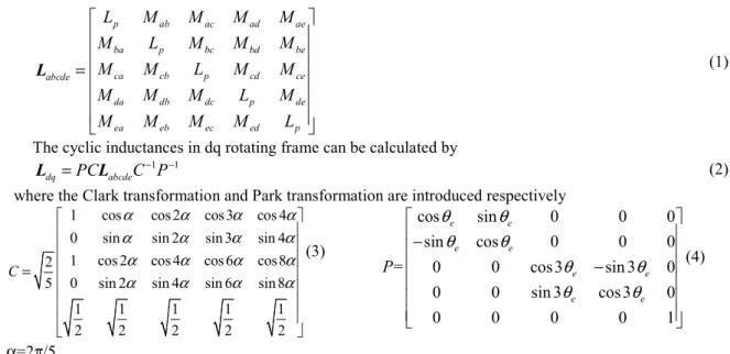
An open-end winding (OEW) five-phase PMSM is designed and studied in this paper. This prototype has 20 stator slots and 14 poles as presented in Fig. 1(a). The rare-earth magnets are buried in the rotor in radial disposition called spoke. Besides, the inverter structure of this open-end winding machine is illustrated in Fig. 1(b). The inductances in natural stator frame are obtained in stator natural frame by a finite element software:
p ab ac ad ae ba p bc bd be ca cb p cd ce abcde da db dc p de ea eb ec ed p L M M M M M L M M M M M L M M M M M L M M M M M L = L (1)
The cyclic inductances in dq rotating frame can be calculated by
1 1
dq =PC abcdeC P− −
L L (2)
where the Clark transformation and Park transformation are introduced respectively
1 cos cos 2 cos3 cos 4
0 sin sin 2 sin 3 sin 4
1 cos 2 cos 4 cos 6 cos8
2
0 sin 2 sin 4 sin 6 sin 8 5 1 1 1 1 1 2 2 2 2 2 C α α α α α α α α α α α α α α α α = (3) α=2π/5 cos sin 0 0 0 sin cos 0 0 0 = 0 0 cos3 sin 3 0 0 0 sin 3 cos3 0 0 0 0 0 1 e e e e e e e e P
θ
θ
θ
θ
θ
θ
θ
θ
− − (4)According to (2), the characteristics of the windings in dq rotating frame, obtained from inductances determined in stator natural frame by a finite element software, are listed in Table I.
Table I: Winding characteristics.
Parameter Value Parameter Value
154.8 µH 199 µH
96.5 µH 97.1 µH
159.2 µH R 0,016 Ω
After analysis of the results of table I, it is will considered only three cyclic inductances L1= (Ld1+Lq1)/2= 177
µH, L3= (Ld3+Lq3)/2= 97 µH, Lh=159µH. It can be remarked that the value of the minimum time constant among
L1/R, L3/R, Lh/R is equal to about 6.1ms. A PWM frequency of 10 kHz will ensure a good control of the average
currents of the machine even for the zero-sequence current which is present in open-winding configuration.
(a) (b) Fig. 1: Finite element model of the machine (a) and drive scheme (b).
In [3], it has been shown that with MTPA strategy the optimal injection of a third harmonic of a machine leads to a torque.
(
)
(
2)
1 1 1 3 3 3 1 1 3 3
5
5
cos
cos
2
cos
3
1
cos
2
2
e m m m RMS m RMS
T
=
p I
λ
θ
+
I
λ
θ
=
p
λ
rI
θ
+
λ
−
r I
θ
(5)Where p is the number of pole pairs, I1 and I3 are the peak amplitudes of the fundamental and the third stator
current harmonics respectively; λm1 and λm3 are the peak amplitudes of the first and the third flux-linkage produced
by permanent magnet respectively; θ1 and θ3 are the angles between the back-EMF harmonic and current harmonic
respectively; r is the ratio between I1 and IRMS (r= I1/ [3]) and IRMS is a given RMS current value.
When no constraints are imposed on current and voltage amplitudes, the optimal values for three parameters
1 1 3 3 2 2 1 1 3 3 3 1 1 3 m m opt m m E E r E E
λ
λ
λ
λ
= = + + θ1=0 θ3=0 (6)E1 and E3 are the first and the third harmonics of no load back-EMF respectively.
In Fig. 2, the no load back-EMFs and the back-EMF/Speed harmonic distribution of the studied machine are presented. Their shapes are clearly non-sinusoidal. The amplitude of the third harmonic is close to 22.7% of the amplitude of the fundamental harmonic. Considering a 5-phase machine, it allows us to generate a constant mean-value torque using the third harmonic. Therefore, according to the amplitude of the injected the third current harmonic should be 22% of the fundamental current harmonic.
(a) (b) Fig. 2: Back-EMF at 750rpm (a) and back-EMF/Speed harmonic distribution (RMS value) (b).
Fig. 3 Torque improvement algorithm 3. Torque Optimization algorithm
Finite element method is an effective tool to analyze and evaluate the design of electrical machine. During the analysis stage, optimal stator currents should be obtained in advance and supplied into the machine. Therefore,
a program developed on MATLAB is used to obtain the optimal current shape that generates the maximum torque considering MTPA and MTPPC strategies. The torque optimizing problem is stated as following. The objective function is
(
)
1 1 3 3 1 1 3 3 1 3
( , , , )I
min
ϕ I ϕ−
T I
e( , , , , , , , , )
θ
I
θ
L
R
λ λ ω
<
0
(7) With the voltage constraint(
)
max
U
abcde≤
60
(8)For the RMS current constraint
2 2 1 3
max
71.4
2
I
I
+
≤
(9)For the peak current constraint
(
)
max
I
abcde≤
120
(10)The Flow chart of the optimization process is illustrated by Fig. 3. The parameters of this program are listed below:
The input inductance matrix L, resistance R and the first harmonic λ1 and the third harmonic λ3 of flux linkage
without load are obtained by a no-load finite element simulation. The optimized parameters are the amplitudes (I1
and I3) and phases (θ1 and θ3) of the first and the third stator current harmonic. The optimizing algorithm is applied
for the interested speed range to obtain the torque-speed characteristic. The objective function should be smaller than zero. If it is larger than zero, it means the machine is at generator mode.
The chosen constraints are associated to three components of the drive: the DC source, the Voltage Source Inverter and the machine. The value of the DC source will impact the maximum voltage which can be imposed to the machine. The OEW connection allows a maximum voltage per phase Uabcde equal to the voltage of the DC
source.
The maximum RMS value, or the current density, which can be imposed in a machine is highly depending on thermal consideration. For example, we can consider that 71.4 Arms(6 A/mm²)) corresponds to steady-state operation (>30 minutes). As the thermal time constant constraints of transistor are less than 0.1s, the chosen peak value of the current Iabcde is associated to maximum allowable value 120A. If the MTPA strategy is applied, the
corresponding stator currents can be optimized with the constraint (9). If the MTPPC strategy is considered, the corresponding optimal stator currents can be obtained with the constraint (10).
4. Optimized results
a. Impact of the third harmonic injection for MTPA strategy
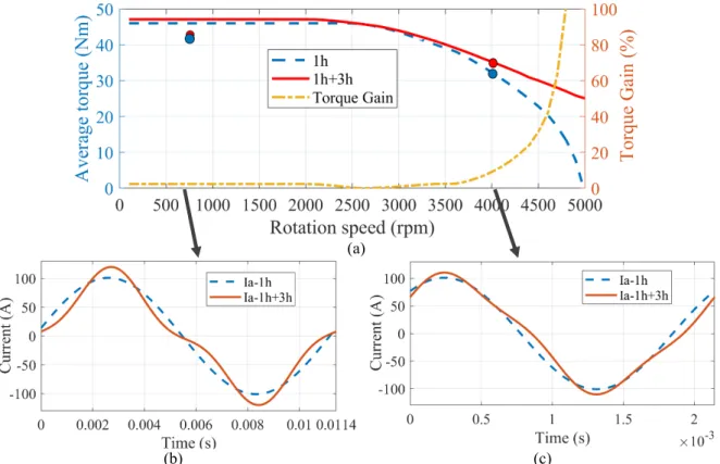
Firstly, the impact of the third harmonic injection is analyzed by the torque improvement algorithm with the current constraint (9). The first case (1h) is to only apply the fundamental current harmonic to optimized torque and the second case (1h+3h) injects the third current harmonic while the same maximum RMS value in both cases is considered. The results are presented in Fig. 4.
Comparing the curves of Fig. 4 (a), it is possible to conclude that the third harmonic current injection allows a torque increase for the same copper losses. The torque increase is quite small at low speed (2,4%). This low gain is expected because the amplitudes of the third harmonic of the current and of the back-EMF are equal to 22% of the fundamental ones. The obtained stator current (phase a) at low speed 750rpm is illustrated in Fig. 4 (b). The current of the second case (1h+3h) is no longer sinusoidal.
When the flux-weakening strategy is implemented, the torque increase overtakes 32% at 4500rpm as shown in Fig. 4 (a). The torque improvement at 5000rpm is over 100% because the available maximum speed is just 4800rpm for the first case (1h). It implies that injecting the third current harmonic can increase the flux-weakening region for the studied five-phase PMSM. The flux-weakening strategy is needed at high speed because the peak back-EMF exceeds the voltage limits of the drive. At high speed, over 2500rpm for this five-phase PMSM, the maximum peak voltage (60V) is a major constraint. The injection of the third harmonic increases from 2 to 4 the number of degrees of freedom (amplitudes and phases of first and third harmonics). By shifting the phase between the third and first harmonics, it is possible to significantly decrease the peak voltage. The resulting peak value of the voltage reference is less than or equal to the voltage limit. An example at 4000rpm is presented in Fig. 4 (c). The current shape is different from the sinusoidal stator current. The produced voltage and back-EMF are illustrated in Fig. 5. It is observed that back-EMF is 90V, but the voltage is reduced to 48V.
At last, the obtained optimal currents of these two cases are applied to the finite element model at speed 750rpm and 4000rpm. The torques are presented in Fig. 4 (a) by the red dots (case 1) and blue dots (case 2). At each speed, the torque is improved by the second case which is same as the conclusion summarized by analytical torque optimization algorithm. The difference is that the torques at 750rpm are smaller than the analytical results.
Because the inductances used in the algorithm are obtained at no load which means there is no saturation. But the finite element model has considered saturation.
(a)
(b) (c) Fig. 4: Torque per speed and torque gain curves with and without third harmonic injection for a current of
71.4Arms (a), with examples of the current shape of the phase-a obtained at 750rpm (b) and 4000rpm (c).
Fig. 5: Current, Back-EMF and Reference Voltage of phase a with third harmonic injection at 4000rpm. b. MTPA and MTPPC strategies
In the previous section, the RMS current is used as a constraint for the machine characterization because this is directly related to the machine copper losses. However, when considering the whole drive, the peak-current is the limitation for the transistors. This is the reason why an analysis will be carried out by not limiting the RMS current but the peak one. This strategy is called MTPPC.
This analysis is only possible when the currents are composed by more than one harmonic, otherwise the peak and the RMS values are directly related. The chosen peak value for the MTPPC strategy is 120Â because it is the maximum peak-current value obtained with the MTPA strategy for the RMS current of 71.4Arms.
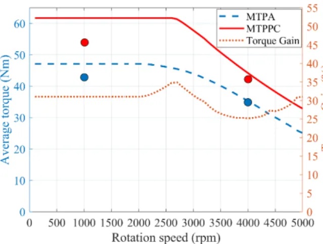
During the optimization, the peak current constraint (10) is used and the results are obtained. Fig. 6 and Fig. 7 present the maximum torque, RMS and peak current per speed curves for the both strategies. These figures confirm that the MTPPC strategy allows the drive to attaint higher values of torque (Fig. 6) without increasing the current peak value (Fig. 7 (b)). At low speed, below 1700rpm, it is possible to have 31% of torque gain for the same peak current, despite a loss increase of 38,6% (Fig. 7 (a)). Different from the comparison of the previous section, the major gain is not in the flux-weakening operation zone.
Fig. 6: Torque per speed curves for MTPA for a RMS current of 71.4Arms and MTPPC for a peak value of 120Â and torque gain percentage of MTPPC in comparison to MTPA.
Fig. 7: RMS current (a) and peak-current (b) per speed curves for MTPA for a RMS current of 71.4Arms and MTPPC for a peak value of 120Â. Fig. 8 shows how different the current shapes are when comparing both strategies. The major difference is the phase shift of the third harmonic. Roughly speaking, the peak-current value when the MTPA strategy is applied is the sum of the first and third harmonics amplitude. This behavior is due to the shape of the back-EMF, intrinsic to the machine. Due to the back-EMF distribution, the third harmonic generates much less torque than the first harmonic. When applying the MTPPC strategy, the third harmonic of the current will be phase-shifted of π from the relative back-EMF harmonic, generating then a negative torque. However, it allows to have a higher first harmonic, consequently a much higher torque, without overtaking the peak-current limit.
Fig. 8: Current shape of the phase a for both strategies at 750rpm.
This behavior is interesting because, in applications such as automotive traction, the higher torque values are usually used during the accelerations. As the duration of those accelerations are relatively short, their impact on machine losses is limited. Finally, torque/speed characteristics of Fig. 6 define which is the most adaptable strategy for each functioning point.
Lastly, these two strategies are simulated at 750rpm and 4000rpm by finite element method. The torques are presented in Fig. 6 by the red dots (MTPPC) and blue dots (MTPA). The torques are larger when MTPPC is applied which is same as the analytical result. The saturation reduces the torques obtained by finite element method. It can be observed the torque is much reduced in MTPPC (12.9% at 750rpm and 4.23% at 4000rpm) than in MTPA (9.8% at 750rpm and 0.23% at 4000rpm). Because the peak currents are same for these strategies, but the RMS current are different. So higher RMS current produces more saturation.
5. Conclusion
The impact of the third harmonic injection on torque generation of a five-phase open-winding PMSM with two different strategies was studied. This third harmonic injection has been optimized in order to generate the maximum torque considering the current limitations of the transistors and the machine. At first, the injected third current harmonic could enlarge the flux-weakening region for the RMS current constraint (MTPA). Besides, the analysis of two constraints with injection of current harmonic allowed us to adapt the control of the drive, in order to increase the torque density of the drive without increasing its sizing. For the same peak current constraint,
MTPPC could produce higher torque than MTPA. But the copper losses could also be larger because of higher RMS current. This control was highly relevant in an industrial context in which the sizing of the machine and the transistors of the inverter are defined together. A possible control for the automobile application was to apply MTPPC for short time such as acceleration and to use MTPA for steady state.
Acknowledgment
This work has been achieved within the framework of CE2I project. CE2I is co-financed by European Union with the financial support of European Regional Development Fund (ERDF), French State and the French Region of Hauts-de France.
References
[1] F. Barrero and M. J. Duran, “Recent Advances in the Design, Modeling, and Control of Multiphase Machines-Part I,” IEEE Transactions on Industrial Electronics, vol. 63, no. 1, pp. 449–458, Jan. 2016. [2] F. Scuiller, H. Zahr, and E. Semail, “Maximum Reachable Torque, Power and Speed for Five-Phase SPM
Machine With Low Armature Reaction,” IEEE Transactions on Energy Conversion, vol. 31, no. 3, pp. 959–969, Sep. 2016.
[3] J. Gong, H. Zahr, E. Semail, M. Trabelsi, B. Aslan, and F. Scuiller, "Design Considerations of Five-Phase Machine with Double p/3p Polarity," IEEE Transactions on Energy Conversion, vol. 34, pp. 12-24, 2018. [4] P. Zhao and G. Yang, “Torque Density Improvement of Five-Phase PMSM Drive for Electric Vehicles
Applications,” Journal of Power Electronics, vol. 11, no. 4, pp. 401–407, Jul. 2011.
[5] K. Wang, Z. Gu, Z. Zhu, and Z. Wu, "Optimum injected harmonics into magnet shape in multiphase surface-mounted PM machine for maximum output torque," IEEE Transactions on Industrial Electronics, vol. 64, pp. 4434-4443, 2017.
[6] M. Slunjski, M. Jones and E. Levi, "Control of a Symmetrical Nine-phase PMSM with Highly Non-Sinusoidal Back-Electromotive Force Using Third Harmonic Current Injection," IECON 2019 - 45th Annual Conference of the IEEE Industrial Electronics Society, Lisbon, Portugal, 2019, pp. 969-974 [7] D. T. Vu, N. K. Nguyen, E. Semail, and T. J. dos Santos Moraes, "Control strategies for non-sinusoidal
multiphase PMSM drives in faulty modes under constraints on copper losses and peak phase voltage," IET
Electric Power Applications, 2019.
[8] Y. Sui, P. Zheng, Y. Fan and J. Zhao, "Research on the vector control strategy of five-phase permanent-magnet synchronous machine based on third-harmonic current injection," 2017 IEEE International Electric Machines and Drives Conference (IEMDC), Miami, FL, 2017, pp. 1-8
[9] G. Feng, C. Lai, M. Kelly, and N. C. Kar, "Dual three-phase PMSM torque modeling and maximum torque per peak current control through optimized harmonic current injection," IEEE Transactions on
Industrial Electronics, vol. 66, pp. 3356-3368, 2018.
[10] D. T. Vu, N. K. Nguyen, E. Semail, and T. J. dos Santos Moraes, "Torque optimization of seven-phase BLDC machines in normal and degraded modes with constraints on current and voltage," The Journal of