UNIVERSITÉ DE MONTRÉAL
OPTIMIZATION OF CUTTING PARAMETERS FOR POCKET MILLING ON
THE SKIN PLATE IN AL AND AL-LI MATERIALS
HADI MORADI
DÉPARTEMENT DE GÉNIE MÉCANIQUE ÉCOLE POLYTECHNIQUE DE MONTRÉAL
MÉMOIRE PRÉSENTÉ EN VUE DE L’OBTENTION DU DIPLÔME DE MAÎTRISE ÈS SCIENCES APPLIQUÉES
(GÉNIE MÉCANIQUE) AVRIL 2014
UNIVERSITÉ DE MONTRÉAL
ÉCOLE POLYTECHNIQUE DE MONTRÉAL
Ce mémoire intitulé:
OPTIMIZATION OF CUTTING PARAMETERS FOR POCKET MILLING ON THE SKIN PLATE IN AL AND AL-LI MATERIALS
présenté par : MORADI Hadi
en vue de l’obtention du diplôme de : Maîtrise ès sciences appliquées a été dûment accepté par le jury d’examen constitué de :
M. MAYER René, Ph.D., président
M. BALAZINSKI Marek, Docteur ès Sciences, membre et directeur de recherche M. BIRGLEN Lionel, Ph.D., membre
DEDICATION
ACKNOWLEDGMENTS
I would like to take this opportunity to express my sincere gratitude to my advisor, Professor Marek Balazinski. Without his thrust, guidance, patience and supports, my research would not have been successful. Undoubtedly, he was the most influential person during my Master of Science program and I hope the bond that we established will continue for many years to come. My immense appreciation extends to the technicians of the laboratory of machining and metrology. They have been very much helpful in the course of this research project.
RÉSUMÉ
L'objectif de cette étude est d'optimiser des paramètres de coupes pour l’usinage de poche sur une plaque mince en alliage d’aluminium et en alliage d’aluminium-lithium. Ces plaques minces sont utilisées dans l’industrie aéronautique pour fabriquer le fuselage d’un avion. Présentement, ces poches sur les plaques minces sont fabriquées par usinage chimique. Cette méthode chimique est dite nocive pour l’environnement. La méthode chimique pourrait être remplacée par une méthode mécanique comme l’usinage. En plus, les paramètres de coupes seront optimisés pour l’alliage d’aluminium-lithium.
L’effet des paramètres de coupes a été étudié par des expériences utilisant la méthode de Taguchi. L’analyse de rapport signal sur bruit (Signal to Noise ratio) a été menée sur les données recueillies pour illustrer la significativité des facteurs des plans d’expériences et de leur contribution. La rugosité de la surface sur les pièces a été aussi étudiée et des paramètres optimaux ont été définis. Des vérifications ont été accomplies et la poche sur la plaque a été usinée à la satisfaction des exigences de l'ingénierie de l'industrie.
ABSTRACT
In the present work the pocket machining (milling) of the thin skin components made of aluminium and aluminium-lithium (Al-Li) alloys is studied. These milled components are known as principle parts of commercial airplanes. They have significant impacts on the airplane body weight and fuel consumption. Chemical milling is the main method used for pockets machining on these components. However, this method is not considered as an environmentally friendly operation due to severe contamination problems. To remedy these difficulties, this study intends to replace the chemical milling by an alternative machining method capable to do pocket machining. To that end, pocket milling was selected as machining method. Furthermore, in order to reduce the weight of airplane, an alternative material such as Al-Li alloys is proposed to replace the aluminum alloys.
In the first phase of this study, a comprehensive literature review was conducted on milling and pocket milling of aluminum and aluminum-lithium alloys. The sample parts required for cutting operations were prepared in accordance with in specified dimensional geometries of the real parts used in industry. A milling fixture was then designed and manufactured in order to perform machining operations on the sample parts. The experimental tests were planned according to the Taguchi method design of experiment. The cutting parameters studied included: RPM, chip thickness (feed rate), depth of cut and lubricant. The one way and profile contouring milling operations were selected as machining strategies. A process failure mode and effect analysis (FMEA) was executed to determine the main failure modes during pocket milling operations and the surface roughness was used as performance criteria.
The experimental results were analyzed using Signal to Noise ratio (S/N) strategy though Taguchi method. According to the experimental results, the optimal setting levels of cutting parameters are RPM (10000 rev/min), chip thickness (0.0508 mm), depth of cut (0.45 mm) and lubricant (MQL, 40 ml/min). Finally, the experimental verification tests were performed.
According to the literature, a similar machining specification can be applied for conventional aluminium alloys and the Al-Li alloys. Consequently, in order to reduce the experimental cost and time, the optimum setting levels of process parameters proposed in this work could be applied in the machining of Al-Li work pieces.
TABLE OF CONTENT
DEDICATION ... III ACKNOWLEDGMENTS ... IV RÉSUMÉ ... V ABSTRACT ... VI TABLE OF CONTENT ... VII LIST OF TABLES ... XI LIST OF FIGURES ... XIII LIST OF ABREVIATIONS ... XVII
INTRODUCTION ... 1
CHAPTER 1 ALUMINUM ALLOYS SPECIFICATION ... 2
1.1 Aluminum Alloys Nomenclature ... 2
1.2 Mechanical and Physical Properties of Al-Li Alloys ... 4
1.3 Application of Al-Li Alloys ... 4
1.4 Production Methods of Al-Li Alloys ... 5
1.5 Commercial Al-Li Alloys... 6
1.6 Two Industrial Sample Parts in Skin Aluminum Shape ... 8
1.7 Classic Manufacturing Method for Pocket on Aluminum Sheet ... 9
CHAPTER 2 MACHINING OF ALUMINUM AND AL-LI ALLOYS ... 11
2.1 Machining of Aluminum Alloys ... 11
2.1.1 Cutting parameters ... 11
2.1.2 Cutting Fluid or Coolant ... 14
2.1.3 Cutting Tool Materials ... 17
2.1.5 Deformation and deflection ... 20
2.1.6 Residual Stress ... 22
2.1.7 Surface Roughness ... 25
2.2 Machining of Al-Li Alloys ... 25
2.3 High Speed Machining (HSM) ... 32
2.3.1Advantages of HSM ... 33
2.3.2 Disadvantages of HSM... 33
CHAPTER 3 FAILURE MODE AND EFFECT ANALYSIS (FMEA) ... 35
3.1 Functions ... 36
3.2 Potential failure mode ... 37
3.3 Potential Effects of Failure ... 37
3.4 Severity ... 37
3.5 Potential Causes of Failure ... 39
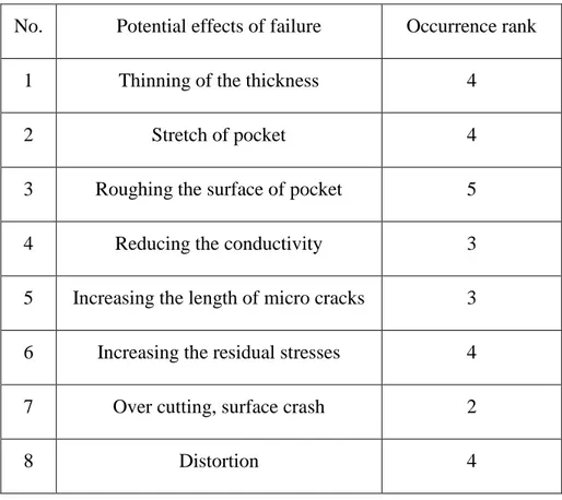
3.6 Occurrence ... 41
3.7 Detection Method ... 42
3.8 Detection ... 43
3.9 Risk Priority Number (RPN) ... 45
CHAPTER 4 TEST SAMPLE PLATE ... 46
CHAPTER 5 FIXTURE DESIGN ... 47
5.1 Fixtures’ Elements ... 47
5.2 Fundamentals of Fixture Design ... 47
5.2.1 Fixture planning ... 47
5.2.2 Fixture Layout ... 48
5.2.4 Tool Body Design ... 48
5.3 Fixture Design Procedure ... 48
5.3.1 Positioning Principles ... 49
5.3.2 Degrees of Freedom of a Workpiece (The motions of the workpiece) ... 49
5.3.3 Clamping principles ... 49
5.4 Designed Fixture for Skin Sample of Al-Li Alloy ... 50
CHAPTER 6 TOOL SELECTION ... 57
CHAPTER 7 DESIGN OF EXPERIMENT (DOE) ... 61
7.1 Procedure of Design of Experiments ... 62
7.2 Problem Statement Definition and Response Variable Selection ... 63
7.3 Factors and levels selection ... 64
7.4 Experimental design selection ... 66
7.5 Experimentation ... 67
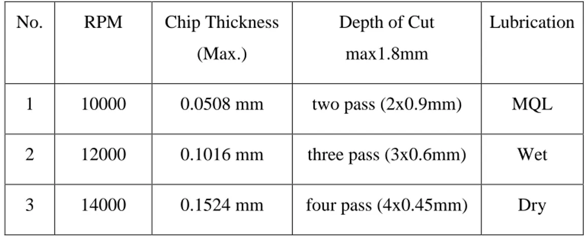
7.5.1 First Test ... 67
7.5.2 Second Test ... 71
7.5.3Third Test ... 76
7.5.4Main Tests ... 77
7.6 Measurement and Test Results ... 78
7.6.1 Surface Quality ... 78
7.6.2 Pocket Deformation ... 91
7.6.3 Bottom Thickness of the Pocket Milled part ... 93
7.6.4 Pocket Dimension ... 95
7.7 Statistical analysis of the data ... 96
7.8 Verification Tests ... 101 CONCLUSION AND RECOMMENDATIONS ... 106 BIBLIOGRAPHIE ... 109
LIST OF TABLES
Table 1.1 Destination system for basic treatment of aluminum alloys ... 3
Table 1.2 Subdivisions of the treatments H and T ... 3
Table 1.3 Al-Li physical properties ... 6
Table 1.4 Major producers of Al-Li alloys ... 7
Table 3.1 Severity process and/or service guidelines ... 38
Table 3.2 The severity ranking proposed for pocket milling of Al-Li skin ... 39
Table 3.3 The causes of potential of failures in pocket milling of Al-Li skin ... 40
Table 3.4 Occurrence of the process and/or service guideline ... 41
Table 3.5 Occurrence rank for pocket milling of Al-Li skin ... 42
Table 3.6 Detection methods used to detect the failure in the pocket milling of Al-Li skin ... 43
Table 3.7 Detection process and/or service guideline ... 44
Table 3.8 Detection ranks of the control methods for pocket milling of Al-Li skin ... 44
Table 3.9 RPN number for the potential effects of failure of pocket milling of Al-Li skin ... 45
Table 5.1 Specification of Mitsui Seiki Hu 40-T ... 53
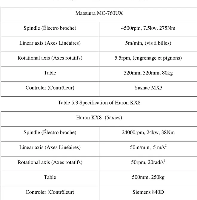
Table 5.2 Specification of Matsuura MC-760UX ... 54
Table 5.3 Specification of Huron KX8 ... 54
Table 7.1 Engineering requirements for aluminum skin sheets with pockets ... 63
Table 7.2 Experimental factors and levels used for the pocket milling of aluminum sheets ... 64
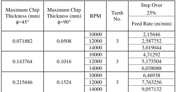
Table 7.3 Calculated feed rates ... 65
Table 7.4 Orthogonal arrays of Taguchi method ... 66
Table 7.5 Orthogonal array L9 of Taguchi method ... 67
Table 7.6 Orthogonal array for pocket milling on the thin skin ... 67
Table 7.8 Machining specification for the second test ... 71
Table 7.9 Machining specification for the third test ... 77
Table 7.10 List of tests after randomization ... 78
Table 7.11 Surface roughness results Ra (µm) ... 84
Table 7.12 Mismatch measurement results for nine test parts ... 90
Table 7.13 Deformation results ... 92
Table 7.14 Bottom thickness measurement results ... 94
Table 7.15 Experimental values of pocket dimension deviations for length and width ... 96
Table 7.16 S/N ratio of the surface roughness values measured in each strategy ... 98
Table 7.17 S/N values for each factor and level for one way strategy ... 98
Table 7.18 S/N values for each factor and level for profile contouring strategy ... 99
Table 7.19 Optimal cutting parameters used ... 101
Table 7.20 Surface roughness Ra (µm) results for two verification tests ... 102
Table 7.21 Mismatch and step measurement results for two verification tests ... 103
Table 7.22 The bottom thickness results for both verification tests ... 104
Table 7.23 Deformation results for two verification tests ... 104
LIST OF FIGURES
Figure 1.1 A common passenger airplane ... 1
Figure 1.2 Al-Li alloy applications in a commercial aircraft ... 5
Figure 1.3 Al-Li alloy applications in a fighter aircraft ... 5
Figure 1.4 Lateral skin of the CRJ 700 ... 8
Figure 1.5 Canopy of Challenger 300 (BD100) ... 8
Figure 1.6 Typical chemical milling set-up ... 10
Figure 2.1 Surface roughness of aluminum parts vs the cutting speed ... 12
Figure 2.2 Commanded and actual feed rate ... 13
Figure 2.3 Typical tool path at the pocket sides ... 13
Figure 2.4 Geometry of a milling process ... 14
Figure 2.5 The examined pieces 8090 and alloy L93 components ... 26
Figure 2.6 Work parts and tungsten carbide tools ... 27
Figure 2.7 Bracket used for dimensional test ... 27
Figure 2.8 Work part used in severe machining condition ... 28
Figure 2.9 The distortion diagram test bars ... 29
Figure 2.10 Aircraft machining chips and scraps of Al-Li material ... 29
Figure 2.11 Chips in the acid salt spary test ... 30
Figure 2.12 Chips in the partial immersion test ... 30
Figure 2.13 Chips in the humidity test ... 31
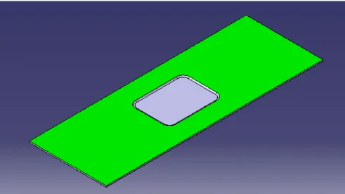
Figure 4.1 Drawing of standard test sample plate ... 46
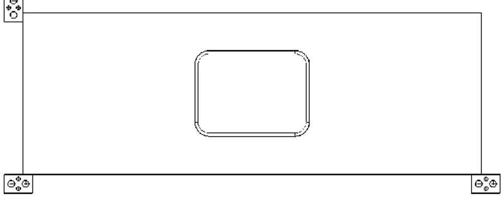
Figure 5.1 Model of standard sample drawing ... 50
Figure 5.2 Locating, supporting and clamping surfaces ... 50
Figure 5.4 Locators (3-2-1) on the locating surfaces ... 51
Figure 5.5 Clamping and supporting systems ... 52
Figure 5.6 New clamping system ... 53
Figure 5.7 Fixture and machine tool table ... 55
Figure 5.8 The raw material provided by Bombardier ... 55
Figure 5.9 The base plate made from aluminum ... 56
Figure 5.10 Overview of the milling fixture ... 56
Figure 6.1 Different solid end mill tools ... 57
Figure 6.2 Different indexable mill tools ... 57
Figure 6.3 Catalog standard number (ISO) ... 58
Figure 6.4 Kennametal standard solid carbide end mill ... 59
Figure 6.5 Kennametal standard insert and index ... 59
Figure 6.6 Bombardier proposed solid carbide tool ... 59
Figure 6.7 Overview of the shrink-fit holder and cutting tool ... 60
Figure 7.1 General model of a process [82] ... 61
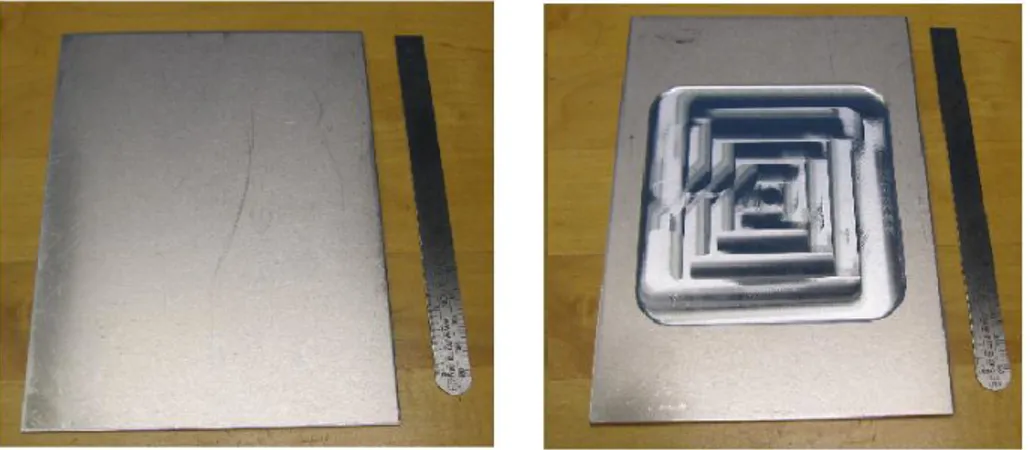
Figure 7.2 The machined sheet metal before and after preliminary test ... 68
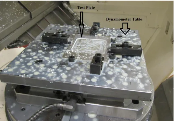
Figure 7.3 Test sheet after pocket milling on the machine and dynamometer table ... 69
Figure 7.4 Cutting force results recorded during the preliminary pocket milling of test ... 70
Figure 7.5 The real size sheet and the modified test set up ... 71
Figure 7.6 The pocket milled sheet ... 72
Figure 7.7 The recorded cutting forces of second test sheet ... 73
Figure 7.8 Probing system and sheet on the table ... 74
Figure 7.9 Deflection profile obtained during pocket milling of the aluminum sheet ... 74
Figure 7.11 The procedure used for surface roughness measurement ... 75
Figure 7.12 Surface roughness Ra (µm) measurement results in different pocket positions ... 76
Figure 7.13 Machining test part for the third test ... 77
Figure 7.14 One way strategy with depth of cut (four passes) ... 78
Figure 7.15 One pass of the one way strategy used for pocket milling ... 80
Figure 7.16 One way strategy used for the pocket machining ... 80
Figure 7.17 Shaped of machined part after implementing the one way strategy ... 81
Figure 7.18 Tool path of profile contouring ... 81
Figure 7.19 Final shape of the work part after pocket machining ... 82
Figure 7.20 Start and end points of profile contouring ... 82
Figure 7.21 Two different surfaces inside the pocket ... 83
Figure 7.22 Surface roughness measurement positions ... 83
Figure 7.23 Auto-correlation function for test part one and line seven ... 85
Figure 7.24 Auto-correlation function for test part six and line four ... 85
Figure 7.25 Auto-correlation function for test part nine and line four ... 86
Figure 7.26 Line four (L4) of test part six and nine ... 86
Figure 7.27 Locations of the worst surface roughness on nine test parts ... 87
Figure 7.28 The Profilometer used ... 88
Figure 7.29 Positions of mismatch measurement ... 88
Figure 7.30 A layout result of mismatch for the first test part and position one ... 89
Figure 7.31 Displacement of test plate during the machining ... 91
Figure 7.32 Deformation measurement procedure ... 91
Figure 7.33 Deformation profile of the work part ... 92
Figure 7.35 Pocket dimension measurement procedure ... 95
Figure 7.36 S/N ratio average for each level of one way strategy ... 100
Figure 7.37 S/N ratio average for each level of profile contouring strategy ... 100
Figure 7.38 The work parts used for verification tests ... 102
Figure 7.39 A layout result of mismatch for the two verification test parts ... 103
LIST OF ABREVIATIONS
Al-Li Aluminum-Lithium
PM Powder Metallurgy
MQL Minimal Quantity of Lubricant HSM High Speed Machining
CAM Computer Aided Manufacturing FEA Finite Element Analysis
FMEA Failure Mode and Effect Analysis CMM Coordinate Measurement Machine RPN Risk Priority Number
DOE Design of Experiment S/N Signal to Nose ratio
INTRODUCTION
As similar as many machines, an airplane consists of many metallic and non-metallic components with various shapes and dimensional geometries (see figure (1.1)).
Figure 1.1 A common passenger airplane [1]
Due to its excellent mechanical properties, aluminum alloys are widely used for the frame of commercial airplanes [2]. To that end, they are usually available as large formed thin sheets. The surfaces of these sheets are also precisely machined with pocket milling operation. Chemical milling is the most common method used for pocket milling. This method is considered non-environmentally friendly as it poses severe difficulties to environment and operators health. The main purpose of this project is to present a strategy to replace the chemical milling by a mechanical milling operation. Furthermore, in order to reduce the weight of airplane and fuel consumption, it is planned to propose new materials instead of commercial aluminium alloys that are currently used in aerospace industry. To that end, this work intends to use Aluminum-Lithium (Al-Li) alloys instead of the common aluminum alloys. In fact, since Al-Li alloys consist of lithium, it has less weight compared to common commercially used aluminum alloys.
In this project, the optimal cutting conditions for pocket milling of aluminum alloys will be defined and accordingly will be applied on Al-Li alloys. This will help the reduction the experimental time and cost. A brief overview of aluminum alloys and Al-Li alloys will be presented in the next sections.
CHAPTER 1 ALUMINUM ALLOYS SPECIFICATION
In this chapter, a general overview of aluminum alloys and Al-Li alloys are presented. The nomenclature of aluminum alloys with mechanical and physical properties of Al-Li alloys are discussed. The main applications and production methods of Al-Li alloys are described. Furthermore, various commercially used Al-Li alloys are introduced.
Two real pocket milled part, currently used in Bombardier products will be presented. Finally, the chemical milling operation that is currently used to generate pockets on thin-skin metal parts are introduced.
1.1 Aluminum Alloys Nomenclature
The Aluminum alloys are classified in the two major categories: cast alloys and wrought alloys. Each category affected by the phase solubility that itself is directionally influenced by the thermal treatment methods. The typical treatment methods are solution heat treatment, quenching, and aging hardening. The nomenclature of wrought alloys nomenclatures are presented with four digit numbers as follows[3] :
1xxx Controlled unalloyed (pure) compositions.
2xxx Alloys in which copper is the principal alloying element, though other elements, notably magnesium, may be specified.
3xxx Alloys in which manganese is the principal alloying element.
4xxx Alloys in which silicon is the principal alloying element.
5xxx Alloys in which magnesium is the principal alloying element.
6xxx Alloys in which magnesium and silicon are principal alloying elements.
7xxx Alloys in which zinc is the principal alloying element, but other elements such as copper, magnesium, chromium, and zirconium may be specified.
8xxx Alloys Consists of tin and some lithium
9xxx Reserved for future use.
The Al-Li alloys can be categorized in group 8xxx. There are three digit numbers and a decimal value (casting alloys limit) for cast alloys nomenclatures as follows [3]:
1xx.x Controlled unalloyed (pure) compositions, especially for rotor manufacture.
2xx.x Alloys in which copper is the principal element, but other elements may be specified.
3xx.x Alloys in which silicon is the principal element, but other elements such as copper and magnesium are specified.
4xx.x Alloys in which silicon is the principal element.
5xx.x Alloys in which magnesium is the principal alloying element.
6xx.x Unused.
7xx.x Alloys in which zinc is the principal element, but other elements such as copper and magnesium may be specified.
8xx.x Alloys in which tin is the principal element.
9xx.x Unused.
The mechanical and heat treatment methods can be applied on aluminum alloys. The correct type of heat treatment method could be identified from specific alphabetic letters and digits added to each aluminium alloy. This system was established by aluminum association and was shown in tables 1.1 and 1.2 [4].
Table 1.1 Destination system for basic treatment of aluminum alloys [4]
F As fabricated
O Annealed wrought products only
H Strain- hardened
W Solution heat-treated
T Thermally treated to produce tempers other than F, O, or H Table 1.2 Subdivisions of the treatments H and T [4]
H1 Strain- hardened only
H2 Strain- hardened and partially annealed
H3 Strain- hardened and stabilized
T1 Cooled from an elevated temperature shaping process and naturally aged T2 Cooled from an elevated temperature shaping process, cold worked, and
naturally aged
T3 Solution heat-treated, cold worked, and naturally aged T4 Solution heat-treated, and naturally aged
T5 Cooled from an elevated temperature shaping process and artificially aged T6 Solution heat-treated, and artificially aged
T8 Solution heat-treated, cold worked, and artificially aged T9 Solution heat-treated, artificially aged, and cold worked
T10 Cooled from an elevated temperature shaping process, cold worked, and artificially aged
1.2 Mechanical and Physical Properties of Al-Li Alloys
Lithium is known as the lightest metal with much lower density (540 (kg/m3)) compared aluminum (2700 (kg/m3)) [5, 6]. Due to unique properties such as high strength and low density, Al-Li alloys are distinguished from aluminum alloys [5, 7]. Higher modulus, excellent cryogenic toughness, and higher stiffness result when more lithium is added to aluminum alloys composition. However this may also reduce the ductility and fracture toughness of the new alloy. Adding 1% of lithium in the aluminum alloy composition may lead to 3% reduction in the density and 5-6% increase in the modulus of the new alloy. It is to underline that the Al-Li alloys have explosion potential when they are melted with water and salt bath, and with fire when they appear as dust [6, 8].
1.3 Application of Al-Li Alloys
The Al-Li alloys are widely used in aerospace industry (military and space applications), where their low weight has significant impacts on efficiency, fuel consumption and aircraft payload [3, 6, 8]. Considering that Al-Li Alloys have significant fatigue resistance, they are used in lower wing surfaces, leading and trailing edges, access covers and seat skins of the commercial airplanes. Furthermore, they are widely used in center fuselage, control surfaces and main wing box of military aircrafts. These alloys are among the best materials for cryogenic applications such as liquid oxygen, hydrogen fuel tanks and tankage of booster systems. Moreover, they are known as a good alternative to aluminum alloys for specific applications in helicopters, rockets and satellite systems [6, 8]. Alloy 1420 was primarily used in MIG-29 aircraft fuselage in the form of welded structure in 1980 [6]. Al-Li alloy applications in commercial and fighter aircraft is shown in figures (1.2, and 1.3).
Figure 1.2 Al-Li alloy applications in a commercial aircraft [3]
Figure 1.3 Al-Li alloy applications in a fighter aircraft [3]
1.4 Production Methods of Al-Li Alloys
Al-Li alloy can be produced by the ingot metallurgy process (IM-process) that is considered as a low-cost process. Another process used to produce this material is powder metallurgy (PM-process). Using this process, different composition and microstructure can be achieved. The
Alcoa Company currently uses these two methods for Al-Li alloy productions. A third method to produced Al-Li alloy is the melt-spinning or splat-cooling process that this process is kind of PM-process [5].
1.5 Commercial Al-Li Alloys
The commercial Al-Li alloys in the market are listed as below:
1- Weldalite 049 (composition(wt%):Cu5.4,Li1.3, Ag0.4, Mg0.4, Zr0.14, bal.Al) 2- Alloy 2090 (composition(wt%):Cu2.7, Li2.2, Zr0.12, bal.Al)
3- Alloy 2091 (composition(wt%):Cu2.1, Li2.0, Zr0.10, bal.Al)
4-
Alloy 8090 (composition(wt%):Cu1.3, Li2.54, Mg0.95, Zr0.12, bal.Al)[8]5-
Alloy 1420 (composition (wt%):Li2.0, Mg5.0, Zr0.1, Si0.15, Fe0.15, bal.Al)6-
Alloy 1421 (composition(wt%):Li2.1, Mg5.2, Si0.1, Fe0.15, bal.Al)7-
Alloy 1460 (composition (wt%):Cu3.0, Li2.0, Si0.15, Fe0.1, bal.Al)8- Alloy1441(composition(wt%):Cu1.75,Li2.0,Mg0.9,Zr0.1,Si0.1,Fe0.1,bal.Al) [6] The mechanical properties of few Al-Li alloys are shown in the table 1.3.
Table 1.3 Al-Li physical properties [8]
Property 2090 2091 8090
Density, g/cm3 2.59 2.58 2.55
Melting range, Cº 560-650 560-670 600-655
Elastic modulus, GPa 76 75 77
Thermal conductivity at 25 Cº, W/m-k 84-92.3 84 93.5
Specific heat at 1000C, J/kg-k 1203 860 930
Table 1.4 Major producers of Al-Li alloys [3]
Producer Alloys Products
Producers with casting facilities
British Alcan 8090 Sheet, plate, extrusions,
forgings
Alcoa 2090, 2091, 8090 Sheet, plate, extrusions,
forgings
Pechiney 2091, 8090, CP276 Sheet, plate, extrusions, forgings
Reynolds Weldalite Sheet, plate, extrusions,
forgings Producers without casting facilities
ILM 8090, 2090 Extrusions
Otto Fuchs 8090 Extrusions, forgings
Menziken 8090 Extrusions
VAW 8090 Extrusions
HyDuty 8090 Forgings
Hoogevens 8090 Sheet, plate
As reported by the European Cooperation for Space Standardization (ECSS), the price of wrought 8090 Al/Li alloy is around 15-18 € per kg [9].
1.6 Two Industrial Sample Parts in Skin Aluminum Shape
The aluminum frame monolithic, ribs and skins are known as large and weak-rigidity structural parts used in the aircraft manufacturing industries [10]. A few of these components have several pockets on their surface. Two types of typical aluminium skin parts were presented by Bombardier as example parts for this study (see Figures1.4 and 1.5).
Figure 1.4 Lateral skin of the CRJ 700
The presented components have the following geometrical and surface characteristics: dimension: 2.420 x 1.050 x 0.650 m; thickness: 1.6 mm; global reduction: 1.47 mm; number of pockets: 33.
Figure 1.5 Canopy of Challenger 300 (BD100)
The skin parts are available in the dimensions of 2.150 m x 1.160 m x 0.720 m, 2.54 mm in the thickness with eight pockets in the surface. These parts are extremely large and thin. Chemical milling is generally used to generate the pockets.
1.7 Classic Manufacturing Method for Pocket on Aluminum Sheet
Chemical milling is widely used in aerospace, electronics, medical and automotive industries. It is basically considered as a corrosion controlled process that is widely used to produce high precision complex shaped components such as a deep interval cavities and miniaturized microelectronics (micro electro mechanical systems (MEMS), semiconductor industries) [11-13]. Other applications of chemical milling include material removal and consequently weight reduction in sheet shaped components and many engineering materials such as steel and silicon [12].
Chemical milling is a material removal process which uses the microscope electrochemical cell action when the workpiece is immersed in a chemical agent [14, 15]. The material removal is conducted by chemical dissolution, strong acidic or alkaline chemical contacts with surface of work-piece [11].
Chemical milling can be used to create and manufacture forms such as pockets, contours, overal metal removal and chemical blanking (thin sheet). Other applications include photochemical (microelectronic parts), chemical or electrochemical polishing (polishing and deburring edge) and chemical jet machining [11, 14].
The main reasons for the increasing demands for chemical milling are [11, 12, 16]: 1- The process is very cheap compared to other manufacturing processes. 2- No special tool and skilled operators are required.
3- The method can be operated relatively fast and simple. 4- There is a lot of information about this process,
5- Generally, no finishing operations are demanded. 6- High precision for complex geometry is possible.
Figure 1.6 Typical chemical milling set-up [17]
However chemical is not considered as an environmentally friendly machining operation, owing to the use of strong acidic or alkaline chemicals for material removal. Therefore, an alternative material removal process is used in this research work.
CHAPTER 2 MACHINING OF ALUMINUM AND AL-LI ALLOYS
Very limited information is available on the machining of Al-Li alloys; it is believed that conventional aluminum alloys and Al-Li alloys have similar machining specifications. Fortunately, since extensive investigations are reported on machining of aluminum alloys, the following passage present the literature review on the milling of aluminum alloys and Al-Li alloys.
2.1 Machining of Aluminum Alloys
The literature review covers factors governing the machining of aluminum alloys such as cutting factors used and the machining responses obtained. The main cutting factors are feed rate and depth of cut), coolant, lubrication mode (MQL, dry), pocket milling strategy, and cutting tools. The main machining responses are surface roughness, cutting forces, deformation, and residual stresses.
2.1.1 Cutting parameters
A relative motion between the workpiece and the cutting tool generates the material removal process in the milling operation. The main cutting parameters involved in milling operation are cutting speed, feed rate and depth of cut. Cutting speed indicates the surface speed at which the workpiece pass the cutting tool, irrespective of the machining operations used. Feed rate is known as the relative velocity as which the cutting tool is advanced against the work part. Depth of cut denotes the volume of the material could be removed in a unit of time. The material removal rate is determined upon appropriate selection of the depth of cut, feed rate and cutting speed [18].
2.1.1.1 Cutting Speed
Cutting speed is calculated by using Eqn 2.1 [19]:
where, Vc is the cutting speed (m/min), D is the diameter of cutting tool (mm) and N is the spindle speed (rpm). According to Eqn. 2.1, the cutting speed is directly proportional to the
cutting tool diameter and spindle speed. Maximum spindle speed is a specification of the machine tool and of the maximum diameter according to the dimension of the pocket.
The maximum allowable cutting speeds for cast and wrought aluminum alloys are 2000 m/min and 4000 m/min, respectively [18, 20, 21].
The cutting tool material is another factor that could limit the cutting speed. Y. Wang et al. studied the wear mechanism of polycrystalline diamond (PCD) tool in high speed milling of Al-Si alloy at cutting speed of 5000 m/min. It should be mentioned that the cutter diameter was 125 mm with 8 inserts and revolution was 12732 (rpm) [22].
Cutting speed has a direct influence in surface roughness of aluminum parts. When cutting speed increases, four main regions appear in the cutting operation as shown in figure (2.1). Region I is affected by build-up edge formation and a deteriorated surface roughness results. The surface quality is improved in Region II when cutting speed is increased. Chatter vibration may occur in region III when cutting speed increases. However, at this cutting condition, acceptable surface quality can be achieved in aluminium alloy. Due to virtual chips, a poor surface finish is observed in region IV [20].
Figure 2.1 Surface roughness of aluminum parts vs the cutting speed [20]
2.1.1.2 Feed Rate
Commanded feed rate could be different along the tool path according to the actual feed rate. The machine tool properties such as acceleration/deceleration and jerk affect the feed rate. The unsmooth acceleration/deceleration control in feed movement is the main reason of tool vibration
in machining operations. Figure (2.2) illustrates the feed rate changing along a pass as cutting tool moves to the end of tool path [23-25].
Figure 2.2 Commanded and actual feed rate
The cutting tool direction in pocket machining changes when the cutting tool reaches the workpiece side. When tool direction changes, the feed rate must stop completely and the cutting tool moves to the next point.
Figure (2.3) presents a common tool path at the boundary of the pocket.
Figure 2.3 Typical tool path at the pocket sides
The feed rate of an end mill along a circular tool path with radius R and the maximum machine acceleration A can be calculated from Eqn. 2.2 [23]:
Another important machining factor is the chip thickness that is directly affected by feed rate and spindle speed. The chip thickness influences the quality of the machined parts. The chip thickness can be calculated from Eqn. 2.3:
where, h(Øj) is the chip thickness, ft is feed rate per tooth and Øj is the instantaneous immersion
angle. The variation of chip thickness in a milling operation varies the cutting forces. The geometry of a milling process as well as chip load and cutting forces are shown in figure (2.4) [26, 27]. The machining time and surface roughness could be changed when feed rate changes.
Figure 2.4 Geometry of a milling process
2.1.2 Cutting Fluid or Coolant
The main benefits of lubrication in machining are: 1- Lubrication of tool/chip/workpiece interfaces. 2- Cooling the workpiece and the tool.
3- Prevent or delay formation of a build-up edge (BUE) on the tool. 4- Prevention of corrosion of the workpiece and/or the machine tool. 5- Help to evacuate the chips out of the cutting area.
Four main types of cutting fluids are straight petroleum-based oils, emulsifiable oils, synthetic fluids, and semisynthetic fluids. The property of straight oil can be improved by adding few materials such as oleic acid, neatsfoot oil, and lard oil to it. There are a few cutting fluids that can be used in harsh cutting conditions such as broaching, tapping, and threading. Adequate rust
preventives, antibacterial agents, and extreme pressure additives could be achieved by using the emulsifiable oils (mixtures of oil and water).Synthetic fluids can be used in milling and turning processes for lubrication and cooling purposes.
The appropriate selection of cutting fluids in high speed machining process depends on many factors such as workpiece material, cutting tool, machining process and cutting speed used. Under dry cutting of the cast iron or Inconel 718, the tool failure may occur due to thermal shock when cubic boron nitride (CBN) tool is used. To avoid tool failure, the cutting zone must be cooled down.
Generally the higher cutting speed increases the cutting temperature. In high speed machining, the cutting temperature mostly transfer out by chips. This allows smooth cutting operations. The lower coefficient of thermal expansion of aluminum alloys than other metals as well as lower cutting forces in aluminium alloys may affect the machined part tolerance in high speed machining operations. The build-up edge (BUE) formation during low speed machining of aluminium alloys may reduce when cutting fluid is used. Chip removal can be done quicker when using cutting fluid. However the cutting fluid does not significantly improve the tool wear rate in high speed machining.
Semisynthetic fluids can be used for machinable aluminium alloys. The main advantages of lubricated machining of aluminum alloys are rapid chip evacuation; adequate cooling of the tool/work surfaces and relatively lower machining cost. It is more necessary to use the cutting fluid for machining of the silicon-containing aluminum alloys than the conventional aluminum alloys. The oils or emulsions are more preferred than the synthetics and semi synthetics.
The cutting fluids should be injected into the cutting surface at an appropriate time. The injection methods are mist cooling, high pressure jets, and shop air [28].The main lubrication strategies applied in machining processes are wet, mist and minimum quantity of lubrication (MQL).
When machining high resistance aerospace alloys (e.g. AlZnMgCu or AlCuMg), the pressure of lubricant is not sufficient for chip evacuation. The MQL seems to be the best solution to overcome this difficulty. The behavior of the cutting tools for high speed milling of Al-Si alloys, as well as the possibility of using MQL were investigated by Lopez et al. [29].
As shown in [29], during milling of a near-eutectic Al-Si alloy (AlSi12CuNi1) under MQL condition, rapid tool wear was observed in uncoated carbide tool than that observed in TiAlN coated carbide tool.
Kishawy et al. investigated the adequacy of different lubrication modes during high speed milling of aluminum alloy A356. Wet (CM2 coolant), dry and MQL (synthetic phosphate ester BM2000 with pressure) conditions were used and the tool wear, surface roughness and cutting forces were measured. It was observed that the better results were obtained under MQL condition [30].
Tsao [31] investigated the end milling of A6061P-T651 aluminum alloy using coated tungsten carbide end mill tool under dry and lubricated conditions. The sulfurous boric acid ester was used as a cutting fluid and lower tool wear was resulted.
Lopez de Lacalle et al. [32] studied the built up edge formation during high speed milling of wrought aluminum alloy (5083-H112). Two cutting fluids techniques such as emulsion of oil in water and spray of oil micro-drops in air were used. As shown in [33], the MQL had better performance than wet condition. As concluded in [32], the nozzle position has a significant effect on the tool life and tool wear.
Zaghbani et al. [34] investigated the fine and ultrafine dust emission during high speed milling of 6061-T6 aluminum alloy in wet and dry conditions. It was observed that the generated energy in the chip formation zone had a direct effect on the dust generation. The particles size is highly affected by the lubrication mode. The submicron size range was produced more in the wet milling than dry milling.
Hwang et al. evaluated the machinability of aluminum alloy (6061) under MQL and wet flood conditions. Higher cutting forces were recorded in MQL compared to wet machining. It was found that the lubrication mode has a significantly affect in the surface roughness [35].
According to Tosun and Huseyinoglu [36], during milling of 7075-T6 aluminum alloy under MQL and wet lubrication conditions, better surface roughness was obtained in MQL condition. The machinability of ball-end milling of aluminum (Al 6063) was investigated under dry, wet and mist cutting conditions [37]. The flow rates 16 (l/min) and 90 (ml/min) were used in wet and mist conditions, respectively. Lower cutting forces and better surface quality were observed in the mist condition than that observed in dry and wet conditions [37].
The lower application of cutting fluids is the primary objective for industries to better protect the environment against contamination and hazardous materials. Boswell and Islam [38] identified the enough environmental cutting fluid for machining of aluminum alloy. No significant results were reported in their previous study on machining of aluminum with minimal quantities of lubrication (MQL) did not show. In their new study, end milling of a hypo-euthectic grade of Al-Si alloy (6061) was conducted and it was found that suitable MQL technique has the most significant impact on tool life compared to other cooling methods. To that end, five cooling conditions were tested such as dry, flood, cooled air, MQL and combined cooled air with MQL. The lowest cutting forces were observed in MQL, combined cooled air with MQL, flood, dry and cooled air. The surface quality when using MQL and combined cooled air with MQL were relatively similar as that observed when using milling with flood coolant. The lower cutting forces were resulted at higher levels of cutting speed when using the MQL and combined cooled air with MQL.
According to reported works in the literature, better surface quality, lower cutting forces, better tool life and chip formation can be achieved under MQL condition. Furthermore, the environment and operators can be protected against hazardous particles as a result of wet machining. Conducting an environmentally friendly machining is also considered as one of the main goals of this research work.
2.1.3 Cutting Tool Materials
The main cutting tool materials used to machine aluminum alloys are tool steel, high-speed steel (HSS), cemented carbide and diamond. The ceramic tools have a chemical interaction with the aluminum matrix and rapid tool failure may occur. The similar problem may occur when the coated carbide integrated with titanium alloy is used. The cubic crystalline boron nitride (CBN) tool is not recommended for machining aluminium alloys [20].
Lopez et al. [29] used the TiAlN coated carbide tool and PCD tool during milling of Al-Si alloys. A rapid tool wear was observed in coated carbide tool. This exhibited that coated carbide tools are not suitable candidates for high speed milling of Al-Si alloys.
Different cutting tools were investigated according to the surface roughness in milling of 7075-T6 aluminum alloy by Tosun and Huseyinoglu. Better surface roughness was achieved by the WC-Co tool [36].
Wang et al. investigated the tool wear mechanism of a polycrystalline diamond (PCD) tool during milling of Al-Si alloy. The diffusion on the flank face and adhesive on the rake face were identified as the main reasons of the tool wear. The high heat generation due to friction at tool-work interface reduced the tool hardness and caused the abrasive wear. The adhesive wear was also resulted by chip pressure [22].
Xu et al. [39] studied the high and low speed milling on 2024-T351 aluminum alloy using TiAlN coated carbide cutting tool. The surface roughness and residual stresses were recorded. According to experimental results, excellent surface quality was obtained under high speed than that observed in low speed.
According to literature, the PCD is considered as the best cutting tool material used in milling of aluminum alloys. The next appropriate tool material is carbide. However as requested by industrial partner, the carbide tools were used in this research study.
2.1.4 Pocket Milling Strategy
Machining time is a considerable machining parameter that can be improved by adequate selection of machining strategy. Machining program generated by CAM soft-ware should be integrated to numerical control unit (NCU) using certain constraints such as speed, accelerations, jerks and tool path. Discontinuity in the tool path resolved by a circular arc in the NCU and there is an equation to identify the radius of the arc. According to Master CAM software, the main pocket machining strategies are zig-zag, parallel spiral, true spiral, morph spiral and one way. The main effective factor on the tool path cycle time is the length of path. The parallel spiral strategy is the most rapid strategy in the Master CAM which does not consider the cinematic behaviors of the machining operation. With respect to the feed rate used, the true spiral strategy is the most rapid method. Another effective parameter on the cycle time is length of segment. This parameter can be calculated by using the interpolation cycle time and the feed rate. If the block length is smaller than the length of segment, the feed rate would be restricted and needs to be
recalculated. The morph spiral strategy has more small size segment and true spiral has bigger segments.
Another criterion of a good strategy is the change of direction in the tool path that can be defined by an angle between two directions. The angles could be divided to following 3 sectors. 0ᵒ to 45ᵒ is most favorable, 45ᵒ to 90ᵒ is costly and 90ᵒ to 180ᵒ is very costly. Morph spiral strategy has shown the best results by means of change in the direction. However this strategy has the greatest number of small segments. In addition, the one strategy is costly when change of direction is required. It could be inferred that the appropriate strategy is divergent parallel spiral strategy [40].
In the machining program, the pockets are two and a half dimensional that these features are the large part of 3axis milling process. Productivity and surface quality are affected by machining strategy generated by CAM system. The stability analysis (uniform cutting load and chatter-vibration), and machining parameters (tool selection, tool path pattern, machining order, etc.) are important elements of machining strategy. Uniform cutting load, as well chatter free condition are the main requirements of high speed pocket milling, that could be achieved by using sub machining region. With respect to type of shape or wall used, the pocket can be classified as simple or complex. If the wall is perpendicular to the base plan, this is a simple pocket while if there is a slant in the wall this can be a complex pocket. The simple pocket can be machined layer by layer in rough and finish machining operations. However, a complex pocket between roughing and finishing a semi-finishing is needed [41].
The tool path of spiral strategy for pocket machining (roughing) could be generated by offsetting the pocket profile. The calculation of the offset’s geometry can be affected by tool’s diameter and the stock allowance. It means that if the tool radius is bigger than the pocket corners radius, it appears that some sections would be removed. In order to avoid overlap in the last path, it is advised to use the lower value of the offset compared to corner radius.
Chatelain et al. [42] proposed new trajectory for spiral strategy that starts in the center of pocket in the circular shape and it was gradually changed to the profile of pocket when the tool comes near the boundary of pocket. This new strategy indicated that the machining time was reduced when larger feed rate was used.
Stability of machining operation is the main concern during high speed machining of the thin component. The chatter vibration may damage the thin webs and results into a poor surface quality. Smith and Dvorak developed a strategy to support the uncut sections of the thin webs parts during high speed milling operations. The cutting tools with no corner radius minimize the normal force to the thin web [43].
In order to improve the surface quality during milling of curved surfaces, Balazinski et al. [44] presented an adequate orientation and direction of cutting tool displacement. A defined scallop height could be achieved in milling by using a method to calculate the step over of a Toroidal cutting tool. The machining error with a shorter and cheaper cutting tool path could be evaluated by this method.
Lee et al. evaluated the effects of tool path and tool angle on deflection and surface integrity of the thin cantilever- shaped aluminum plate during high speed ball end milling operation. The maximum deflection was observed when the 45° tilt angle was used [45].
Vakondios et al. examined the effects of various milling strategies (vertical, push, pull, oblique, oblique push and oblique pull) and cutting parameters (axial and radial depth of cut, feed rate, inclination tilt and lead angles) on surface roughness of ball end milled Al7075-T6 parts. The best surface quality was observed when using inclination angles ±5° [46].
According to the literature, the main pocket milling strategies are internal and external spiral, zigzag, and one way strategies. The lower machining time, higher stability and better surface quality are the quality characteristics proposed for better selection of milling strategies. In this project, one way strategy was selected as a desirable strategy which allows pocket milling on the double curved surfaced of the thin-skin parts.
2.1.5 Deformation and deflection
There are six orders of deviation from the nominal form of the surface. The first order deviation is resulted by machine tool errors, work piece deformation, and unsuitable clamping. The second order deviation arises from geometry tolerances such as flatness, circularity, and waviness. The shape and condition of the cutting edge, chip formation and the process kinematics affect the
third and fourth orders of deviation. The structure of the workpiece material such as physical and chemical mechanisms (e.g. slip, diffusion, and residual stress) have the crucial effects on the fifth and sixth order deviations [46]. Distortion and deformation are resulted from residual stress. The thermal strain, elastic-plastic strain and micro structural changes are the main governing factors on the residual stresses, which themselves are strongly affected by tool geometries, cutting conditions used and work materials [47].
Guo et al. [48] established a 3D finite element model (FEM) to predict the machining deformation of the thin-walled frames. The cutting forces, clamping forces and initial residual stresses were studied.
The deformation of the thin plate of aluminum alloy during milling operation was reported in [49]. The work part used was a cantilever plate of 7075 aluminum alloy. It was found that the heat generation is not the main reason of deflections, while they are generated by residual stress after milling operations. The recorded residual stresses were 400 MPa on the surface and zero at the 0.05mm depth.
Aijun and Zhanqiang [50] proposed a new analytical model to predict the static deformation of thin-wall plate with low rigidity. A theoretical deformation model was developed by finite element method (FEM) to predict the part deformation. In regard to milling forces, location of cutter and the thickness of part, the geometrical accuracy of the thin-wall plate could be increased using this method.
Cao el al. [51] analyzed errors of the side walls of aluminum LY12CZ in milling operation, when different cutting condition were used. The lower deformation is resulted when the rigidity of machining area is increased.
According to Wang et al. [52], the milling cutting forces are the main governing factors on the work part deformation.
S. Lin et al. [53] studied the effects of fixturing on the deformation of the thin-walled milled part. As reported in [53], the main governing factors on the milled work part deformation are cutting forces, fixtures, fiber direction of material, plastic deformation and cutting strategy.
Huzeng et al. [19] introduced a method and instrument to measure the cutting force in high speed milling of wrought aluminum alloy in 2012. It was reported that the lower cutting forces and
work part deformation are resulted when using down milling with lower levels of depth of cut and feed rate.
The deflection of the thin-wall work parts are strongly affected by the work part thickness and properties. The deflection of different milled aluminum alloys were studied by Han et al. it was found that the material strength has no significant effect on the deflection. Lower defection is resulted when suing thicker material. This in fact increases the structural stiffness [2].
Lower cutting forces and deflection were resulted when high speed machining was used.
2.1.6 Residual Stress
Aluminum alloys can be machined at high levels of feed rate and cutting speed. The subsurface of machined work part is affected by thermal and mechanical loads. These loads could be changed by cutting conditions. The scrape rate can be reduced when residual stress reduces. It is important to identify the effects of residual stresses in machining of aluminium alloys.
Special attention has been paid to material removal in the past few years, since it is observed that several parts need to be machined up to 95% of their weights. The thin plates were developed in the aerospace industries to better reduce the fuel consumption. One main difficulty is to understand the effect of cutting parameters on machining responses when the shape and size of machined part is changed. For instance, the relationship between the residual stress and variation of cutting parameters, cooling strategy and tool geometry are yet to be understood.
The high performance cutting (HPC) is recently developed to improve the performance of the machine tools and cutting tools and increase the material removal rate. In HPC, higher levels of feed rate and cutting speeds are used to decrease the machining time. Decreased residual stress may increase the work part life time, especially in thin plates.
The residual stress appears in the raw material, even if no mechanical stresses, such as axial load, force, torques or thermal gradient are applied. These stresses could be affected by mechanical and thermal loads.
The residual stress can be grouped into tensile and compressive residual stresses, which are both widely affected by thermal and mechanical loads. The final residual stress would be the superposition of the residual stresses in the raw material and machining processes.
The residual stresses could be controlled by modification of the machining process parameters and consequently the mechanical and thermal loads. The mechanical loads cause the compressive residual stresses and the thermal loads cause the tensile residual stresses. It is strongly suggested to define the relationship between the machining parameters and tool geometries with mentioned loads.
Few studies reported the effects of machining parameters on the residual stresses aluminum alloys. The effect of high speed cutting on the residual stresses in turning and milling was investigated by Ploger and Gey [21].
The residual stresses in milling of forged aluminum alloys were studied by Denkena et al. Various levels of cutting speed and feed per tooth were used and the initial residual stress of ±25MPa was recorded. Moreover, the maximum compressive residual stresses were observed around the thickness of 50 µm. It was discovered that when feed rate increases from 0.2mm to 0.3mm, an increased compressive residual stress is observed in the deeper layer of surface. It is to note that at higher levels of cutting speed and feed rate, the lower compressive residual stress was observed in dry machining compared to that observed in wet machining. The residual stress generally varies when milling tools with various corner radiuses are used.
At lower corner radius, the compressive residual stresses tend to decrease. When the biggest radius rƐ=1.5mm is used, a machined surface free of residual stresses would appear [21].
Residual stresses are the marked effects on the surface integrity that may affect fatigue life of the machined part as well as the assembly operations. Shot-peening process is generally used to adjust the level of compressive residual stress. Although the mechanisms of residual stresses are yet to be found, but it is thought that the plastic deformation and thermal loads are the main reasons of the residual stress [54].
Yuanwei [55] developed a FEM model of high speed milling of 7075-T7351 aluminium alloy and studied the effects of the residual stress on component life. The simulation results fitted well with those recorded experimentally. It was found that the main reason of distortion is the original residual stresses.
C. Fu et al. [10] used finite element model (FEM) to predict the machining cutting forces and stresses in high speed end milling 7075 aluminium alloy.
As shown in [39], et al. in 2012, the original compressive residual stresses could be increased when using high speed. However, low level of speed, they might change to tensile residual stress. The results show that machining feed in perpendicular to the pre-stretch direction of the part increases the compressive stresses, especially in high speed machining.
Cai et al. [56] studied the surface topography, surface roughness and residual stress profile in high speed milling operation. Blank residual stresses as constant bias were observed. The residual stress had a variation range of ±60 MPa from superficial surface to depth 90µm. The residual stress at depth of 0µm was changed from tensile to compressive modes, when cutting speed was increased. At cutting speed 1000 (m/min) the compressive residual stress was changed to tensile when higher levels of depth of cut were used. By moving into the work part and changing the cutting speed from 600 to 800 (m/min), residual stresses changed from tensile to the compressive. Vice versa, at cutting speed 400 m/min, the compressive residual stress was changed to tensile residual stress.
The effects of cutting parameters and cutting temperature on the surface roughness and residual stresses in high speed milling of aluminum alloys were reported in [57]. Higher tensile stresses were recorded at cutting speed interval 250- 1250 (m/min). An increased feed per tooth led to higher cutting forces, residual stress and cutting temperature.
Li et al. [58] studied the effect of cutting speed and feed rate on residual stresses during milling of 7075T7451 aluminum alloy. It could be stated that the cutting speed and the feed rate had the same impact on the recorded residual stresses in the feed and orthogonal machining directions. The mechanical load was found as the main effective factor on the compressive residual stresses. It was observed that the residual stress is not affected at higher cutting speed. The normal direction of cutting according to the feed had a compressive residual stresses. The optimal compressive residual stress was achieved at feed rate 2500-2600 (mm/min).
A mathematical model to predict the surface residual stress in end milling operation was proposed in [47]. The Taguchi’s L16 orthogonal array was used as design of experiment. The investigated cutting factors were cutting speed; feed rate, radial and axial depth of cut. The maximum compressive stress was recorded at cutting speed 376.8 m/min, feed rate 0.13 mm/z, radial and axial depth of cut 3 and1mm.
2.1.7 Surface Roughness
Higher friction coefficients appear between the rough surfaces than smooth surfaces. The mechanical performance of the parts could be predicted by surface roughness, because the cracks and corrosion could occur quicker on the rough surfaces. Controlling the surface roughness is difficult and expensive task [59].
Machined surfaces, especially milled surfaces are widely used in the assembly. The better surface quality may improve the fatigue strength and creep. The surface roughness could affect several functional attributes such as heat transmission, ability to keep the lubricant, surface friction, wearing etc. The main factors that affect the quality of machined surfaces are material properties, cutting parameters, tool geometry, and machining strategy [60]. This exhibits that the simultaneous control and improvement of the surface quality is considered as a difficult task. An excellent surface quality can be achieved when appropriate cutting parameters and control strategies are used [61].
2.2 Machining of Al-Li Alloys
As literature review of Al-Li alloys machining, it should be mentioned that there are a few studies and researches in this area. In the other hand, there are a lot of studies and researches about the mechanical properties of Al-Li alloys in comparison of the conventional aluminum alloys [6]. As reported by European Cooperation for Space Standardization (ECSS) [9], similar characteristics were observed during machining of Al-Li alloys and other commercial aluminum alloys.
The research work done by Mould and Frod [62], in corporation with British Aerospace PLC is considered as the primary source of information on machinability of Al-Li alloy 8090. No significant difference was observed in terms of machine tools, cutting tools, and equipment for machining. It was a user experience during a production process and the response of experimental test.
Distortion and close up of the flange and behavior of slot in an enclosed pocket were examined during machining of two pieces with material FHD 8090 and FHD alloy L93 components as illustrated in the figure (2.5).
Figure 2.5 The examined pieces 8090 and alloy L93 components [62]
Standard aerospace M42 (HSS) with two tooth and four tooth milling cutters were used. The results were compared with machining results of a L93. The K20 carbide was used to clean up the surfaces of the materials 8090 and L93. It seems that behavior of material Al-Li (8090) is like a pure aluminum [62].
The distortion of flange (Fig 1.6) was less than 120μm, when a machining length of 105 mm was used. The experimental results can be confirmed by experimental verifications in the production line. Further cutting operation were conducted on these materials to investigate the distortion characteristics, surface texture and high flanges when tungsten carbide cutting tools were used.The work pieces for this test are shown in figure (2.6) [62].
Figure 2.6 Work parts and tungsten carbide tools [62]
A conventional water soluble mineral oil at 40:1 ratio was used as coolant in this work. Proof, tensile and elongation result were fitted with tolerance when the material arrived in solutionised condition normal. The rough machining was conducted at speed 1200 mm/min at 6000 r.p.m while finishing operations was performed at feed rate 500 mm/min and speed 6000 r.p.m. These cutting parameters were selected to reduce the stress in the machined part [62].
One more cutting test was performed to investigate the dimension results for drawn work part tolerances. The corrected tolerances were obtained for two materials. The work piece for this test was the BAe 146 aircraft as shown in figure (2.7) [62].
Figure 2.7 Bracket used for dimensional test [62]
Another machining test was performed to define the distortion and cutter burn according to overheating of the material [62].
As reported in [62], the Al-Li 8090 has the similar machinability as those observed for conventional aluminum alloys.
Finally the last machining test was conducted on the work part shown in the figure (2.8). The cutting parameters used were feed /surface speed ratios excessive to normal practice, tool materials and geometries known to burn L93 and worn tools to machining the material Al-Li 8090. The following observations were made:
1- The work part 8090 Al-Li alloy was machined better under the FHT condition. 2- There is no need to change the cutting tool material (HSS or tungsten carbide). 3- There is no need to change the metal removal machine tool [62].
Figure 2.8 Work part used in severe machining condition [62]
Lequeu et al. designed a new copper-lithium alloy (2050) to produce medium and thick plates. The new product was tested in barrel machining method and the distortion and residual stress were recorded. Two test bars L & LT are used in this method and the full thickness will be controlled in machining. A stiff structure was made and the machining behavior of this material was evaluated from unsymmetrical machining operation. the diagram of distortion of the tests bar are shown in figure (2.9) [63].
Figure 2.9 The distortion diagram test bars [63]
As presented in the in the figure (1.9), the Al-Li alloy 2050 work parts has negligible deflection in the LT. According to reported results in [63], the machining strategy and off-set can be kept constant.
Wilson et al. in corporation with Alcan international Ltd. investigated the recycling of the Al-Li chips and scraps in 1987 and 1993. Various parameters such as cost of scrap, strategy, storage, drying and de-oiling and recovery of Al-Li scraps were investigated. The aircraft machining chips and scraps are shown in the figure (2.10) [64, 65].
Figure 2.10 Aircraft machining chips and scraps of Al-Li material [64]
The generated chips when machining Al-Li materials were compared with those observed when machining other aluminum alloys such as 7075, 2014, 2024. Al-Li materials have better corrosion resistance than conventional aluminum alloys. The processes to define this advantage of Al-Li material are shown in the figures (2.11, 12, and 13) [65].
Figure 2.11 Chips in the acid salt spary test [65]
Figure 2.13 Chips in the humidity test [65]
Astronautics Laboratory (AFSC) by National Institute of Standards and technology presented the compatibility of aluminum alloys (8090-T3 and 2090-T81, WL049-T351 and Al alloy 2219) for Cryogenic Tanks. The machining results of impact specimens showed that they were highly variable. The surface roughness of alloy 8090-T3 and alloy 2090-T81 were in the ranges of 40-60µin and 16-20µin respectively. The specimens thickness tolerances were also ±0.005 in [66]. Machinability of alloy 2090 was compared with the B-rated aerospace alloys, 2024-T351 and 7075-T65 [3]. The machining chips in B-rated aerospace alloys can be easily broken and a good surface finish can be achieved. Strong supporting and fixture techniques must be performed when machining material 2090. It is proposed to use sharp positive-rake angled tools and coolant during the machining of alloy 2090.
The manufacturing of Al-Li alloys (2090, 2096, 2098, 2195, L277, C458, 2297, and 2397) were compared by the non-Li aluminum alloys (2219, 2024, 7075, 7050, 6061) [67].
2.3 High Speed Machining (HSM)
High speed machining is considered as an economical, technical, and social evaluation in the manufacturing science. With respect to economical evolution, increased quantity of products require more advanced cost management approach [68].
According to predefined tool life, different cutting speeds can be used in each material. The higher speed can be used in high-speed machining when the shear localization could be developed completely in the primary shear zone [69]. However, this definition is not applicable in practice [70].
Salomon conducted several machining tests in the late 1920's on nonferrous metals such as aluminum, copper and bronze at wide range of speeds up to 16,500 m/min (550 m/s). According to Salomon, there is a maximum increasing temperature in the machining at a given cutting speed and by increasing the cutting speed the temperature decreased. And by using this rule the high speeds could be executed to have better cutting conditions. At the late 1950's, more advanced research studies in high speed machining were proposed. Up until to the mid-80's, the major industrial demands from high speed machining were prosing strategies to reduce forces, stresses and tool wear. However, segmented chip formation was also observed in, which is not however favorable in high speed machining [69, 71].
Many industrial sectors such as defense, aerospace and automotive use the high speed machining technology. Many aerospace manufacturing companies use the carbide tool in high speed micro and macro cutting operations [70]. High-speed machining of thin walled aluminum components is considered as a cost effective machining process that require high removal from the bulk material [69].
Other industries such as tool and die industries use high speed machining. Since high speed machining of hard metal is a complicated task, the heat treatment and annealing condition are generally used to decrease the hardness of the hard metals. The grinding and nontraditional machining processes such as electro discharge machining (EDM) could be used to machine hard materials. These processes are expensive, but since high speed machining tools can be directly applied in these systems, higher production rate and less manufacturing cost are anticipated [72].
![Figure 1.3 Al-Li alloy applications in a fighter aircraft [3] 1.4 Production Methods of Al-Li Alloys](https://thumb-eu.123doks.com/thumbv2/123doknet/2340361.33758/22.918.231.697.553.866/figure-alloy-applications-fighter-aircraft-production-methods-alloys.webp)
![Figure 2.10 Aircraft machining chips and scraps of Al-Li material [64]](https://thumb-eu.123doks.com/thumbv2/123doknet/2340361.33758/46.918.267.659.638.904/figure-aircraft-machining-chips-scraps-al-li-material.webp)