HAL Id: tel-00719312
https://tel.archives-ouvertes.fr/tel-00719312
Submitted on 19 Jul 2012
HAL is a multi-disciplinary open access archive for the deposit and dissemination of sci-entific research documents, whether they are pub-lished or not. The documents may come from teaching and research institutions in France or abroad, or from public or private research centers.
L’archive ouverte pluridisciplinaire HAL, est destinée au dépôt et à la diffusion de documents scientifiques de niveau recherche, publiés ou non, émanant des établissements d’enseignement et de recherche français ou étrangers, des laboratoires publics ou privés.
dedicated to DVB-T2
Meng Li
To cite this version:
Meng Li. Design, implementation and prototyping of an iterative receiver for bit-interleaved coded modulation system dedicated to DVB-T2. Signal and Image processing. Télécom Bretagne, Université de Bretagne-Sud, 2012. English. �tel-00719312�
No d’ordre : 2012telb0225
Thèse
présentée à
TELECOM BRETAGNE
en habilitation conjointe avec l’Université de Bretagne Sud
pour obtenir le grade de
DOCTEUR de Telecom Bretagne
Mention : Sciences et technologies de l’information et de la communication
par
Meng LI
Design, implementation and prototyping of an
iterative receiver for bit-interleaved coded
modulation system dedicated to DVB-T2
Soutenance prévue le 11 janvier 2012 :
Composition du Jury :
Directeurs
: Catherine Douillard, Professeure, Télécom Bretagne
: Christophe Jégo, Professeur des Universités, IPB Bordeaux
Encadrant
: Charbel Abdel Nour, Maître de Conférences, Télécom Bretagne
Rapporteurs
: Fabienne Nouvel, Maître de Conférences HDR, INSA de Rennes
: Jean-Marie Gorce, Professeur des Universités, INSA de Lyon
Examinateurs : Gérard Faria, Directeur Général, Teamcast Rennes
Contents
Table of contents iv
Introduction 1
1 Background 5
1.1 A digital communication system . . . 6
1.2 Error control codes . . . 6
1.2.1 Linear block codes . . . 7
1.2.2 Convolutional codes . . . 8
1.2.3 Concatenated codes . . . 9
1.2.4 Turbo codes . . . 9
1.2.5 Low density parity check codes . . . 10
1.3 The fading channel model . . . 11
1.3.1 General description of fading channel . . . 12
1.3.2 Rayleigh fading channel model . . . 14
1.3.3 Single Frequency Network . . . 17
1.3.4 Channel model for the fading channel with erasures . . . 17
1.4 Coded Modulation . . . 17
1.4.1 Trellis coded modulation . . . 18
1.4.2 Pragmatic trellis coded modulation . . . 19
1.4.3 Bit-interleaved coded modulation . . . 19
1.4.4 Improving the performance of BICM system over a fading channel . . 21
1.5 DVB-T2 standard introduction . . . 22 i
1.5.1 Advanced bit-interleaved coded modulation for the DVB-T2 standard 24
1.5.2 LDPC codes of DVB-T2 . . . 26
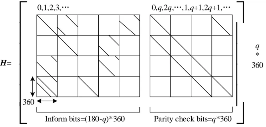
1.5.2.1 Encoding method of LDPC codes in DVB-T2 . . . 27
1.5.2.2 Properties of LDPC codes in DVB-T2 . . . 29
1.6 Conclusion . . . 30
2 Design and implementation of a flexible demapper 33 2.1 Demapping algorithm for non-rotated QAM . . . 34
2.2 Demapping algorithms for rotated QAM . . . 37
2.2.1 One-dimensional demapping algorithm . . . 37
2.2.2 Two-dimensional demapping algorithm and simplification . . . 40
2.2.3 Performance comparison . . . 42
2.3 Architecture of a flexible demapper for DVB-T2 . . . 44
2.3.1 Simplification of the Euclidean distance computation . . . 45
2.3.2 Architecture of a 2D demapper based on sub-region detection . . . . 46
2.3.3 Choice of the number of quantization bits . . . 49
2.3.4 Logic synthesis results . . . 51
2.3.5 BER performance . . . 51
2.4 Conclusion . . . 52
3 Design and implementation of a vertical shuffled LDPC decoder 57 3.1 Background . . . 59
3.2 Two phase message passing decoding algorithm . . . 59
3.3 Check node process simplification . . . 64
3.3.1 Check node process based on Gallager’s approach . . . 64
3.3.2 Check node process based on Jacobian logarithm . . . 65
3.3.3 Check node process based on normalized Min-Sum . . . 67
3.3.4 Check node process based on offset Min-Sum . . . 67
3.3.5 Check node process based on lambda-Min-Sum . . . 68
3.3.6 Summary . . . 69
CONTENTS iii
3.4.1 Horizontal shuffled normalized Min-Sum decoding algorithm . . . 70
3.5 Vertical shuffled decoding algorithm . . . 71
3.5.1 Vertical shuffled normalized Min-Sum decoding algorithm . . . 72
3.6 Performance comparison . . . 73
3.7 Design and implementation of a vertical shuffled Min-Sum LDPC decoder . . 75
3.7.1 The design of a vertical shuffled normalized Min-Sum LDPC decoder . 75 3.7.1.1 The architecture of the proposed LDPC decoder . . . 75
3.7.1.2 The timing schedule of the proposed LDPC decoder . . . 76
3.7.1.3 Memory management . . . 77
3.7.1.4 Sub-matrix split . . . 79
3.7.2 Avoiding message passing inefficiency caused by double diagonal sub-matrices . . . 81
3.7.2.1 Message update conflict problem . . . 81
3.7.2.2 Methods to avoid message update conflict for horizontal shuf-fled decoding algorithm . . . 83
3.7.2.3 Methods to avoid message update conflict for vertical shuffled decoding algorithm . . . 86
3.7.3 Avoiding memory access conflict caused by a pipeline architecture . . 87
3.7.4 Logic synthesis results . . . 91
3.8 Prototype of a simplified DVB-T2 transceiver system . . . 92
3.8.1 Simplified DVB-T2 transceiver system . . . 93
3.8.2 Transmitter elements . . . 93
3.8.2.1 Pseudo random generator . . . 93
3.8.2.2 LDPC encoder . . . 94 3.8.2.3 Bit interleaver . . . 94 3.8.2.4 Mapper . . . 96 3.8.3 Channel emulator . . . 97 3.8.4 Receiver elements . . . 98 3.8.4.1 Equalizer . . . 100 3.8.4.2 Demapper . . . 101 3.8.4.3 Bit de-interleaver . . . 102
3.8.4.4 LDPC decoder . . . 102 3.8.5 System platform . . . 103 3.8.6 Performance . . . 104 3.9 Integration of the demapper and decoder in a complete DVB-T2 system . . . 108 3.9.1 System platform . . . 108 3.9.2 Prototype and performance . . . 108 3.10 Conclusion . . . 112 4 Design and implementation of an iterative BICM receiver for DVB-T2 113 4.1 Algorithm design for an iterative BICM receiver . . . 115 4.1.1 Demapping algorithm for an iterative BICM receiver . . . 115 4.1.2 Decoding algorithm for an iterative BICM receiver . . . 117 4.1.3 A joint shuffled demapping and decoding algorithm for an iterative
BICM receiver . . . 120 4.1.4 Message passing schedules between LDPC demapper and decoder for
an iterative BICM receiver . . . 122 4.2 Design and implementation of an iterative BICM receiver . . . 125 4.2.1 Architecture of an iterative BICM receiver . . . 127 4.2.2 The prototyping of the iterative BICM transceiver onto an experimental
setup . . . 130 4.3 Conclusion . . . 133 Conclusion 135 Publications 139 Glossary 141 List of figures 143 List of tables 149
Introduction
Context:
The emergence of new market driven services such as High Definition (HD) television and 3D-TV have offered unprecedented user experience creating a real need for improving nowadays transmission systems. A better use of the scarce spectrum resources became a must leading to the development of next generation broadcasting systems.
Single Frequency Network (SFN) is a way to increase spectral efficiency. It consists of a broadcast network where several transmitters simultaneously send the same signal over the same frequency channel. While spectrally efficient, such a topology can lead to a severe form of multipath propagation. Indeed, the receiver sees several echoes of the same signal, the destructive interference among these echoes known as self-interference may result in additional fade events. This is problematic especially in wideband communication and high-data rate digital communications, since the frequency-selective fading and the Inter-symbol Interference (ISI) caused by the time spreading of the echoes greatly deteriorate the system performance in terms of Bit Error Rate (BER).
Spectral efficiency should not come at the price of reduced robustness. Therefore, nu-merous technical aspects are to be improved from first generation systems including source coding, channel coding, interleaving, modulation, diversity etc.
In 2008, the European Digital Video Broadcasting (DVB) standardization committee launched the second generation of Digital Video Broadcasting-Terrestrial (DVB-T2) stan-dard [1]. As the successor of DVB-T, it introduces several enhancements to the transmission system including the 4th generation of the Moving Picture Experts Group (MPEG4) source coding, multiple physical layer pipes, a state-of-the-art forward error correcting codes: Low Density Parity Check (LDPC) [2] + Bose Ray-Chaudhuri Hocquenghem (BCH) [3], increased diversity thanks to a longer channel interleaver and the introduction of a diversity technique at the signal space level, a Multiple Input Single Output (MISO) Alamouti [4] based-scheme, etc.
Since the invention of turbo codes in 1993 [5], iterative processing has found its way 1
into numerous domains. The Low Density Parity Check (LDPC) codes are another branch of powerful iterative codes, which was re-found [6] after the invention of Turbo codes. In digital communications, the iterative process called turbo principle was extended to additional blocks than the traditional FEC. Indeed, an iterative process between an FEC decoder and a soft Multiple Input Multiple Output (MIMO) detector [7] or a demapper or an interference canceller has proven to improve performance. The iterative process between a demapper and a LDPC decoder was recommended in the implementation guideline of DVB-T2 standard in order to improve the performance over fading channel without and with erasures. The fading channel with erasures represents the case of a severe fading in SFN network.
Objectives:
In this document, we restrict ourselves to techniques that intended to improve throughput and reliability in the context of channel coding, diversity and modulation. The main objective of our study is to design a DVB-T2 receiver that can achieve high throughput for an acceptable hardware complexity. Moreover, the proposed receiver has to support both non-iterative pro-cess and iterative propro-cess. However, practical applications are reluctant to mandate solutions based on iterative processes due to some challenges and constraints in terms of increased hardware complexity, memory access conflicts and additional latency.
Signal Space Diversity (SSD) [8] can improve the robustness of the DVB-T2 system and mitigate the effects of self-interference due to SFN. While improving performance, SSD in-troduces additional complexity especially for spectrally efficient constellation sizes. DVB-T2 is the first standard to adopt signal space diversity with high order constellation such as 256-QAM. In this case, the classical one dimensional Max-Log demapping algorithm applied on log(M ) PAM based on de-coupling the I and Q components is not applicable. The quest for a hardware efficient SSD demapper is raised and not addressed yet.
The Low Density Parity Check (LDPC) codes are defined by their parity check matrices. The double diagonal sub-matrices in the parity check matrix of the LDPC codes induce message update conflicts problem in the shuffled LDPC decoding algorithm. In the meanwhile, the memory access problem caused by scheduling induces inefficient message passing between the check nodes and bit nodes. These are two crucial problems that have to be addressed for designing an LDPC decoder dedicated to the DVB-T2 standard.
A classical iterative receiver is frame-based, which induces large latency. The latency is introduced by the block interleaving/de-interleaving, which is based on memory writing and reading. The latency is also due to the state-of-art LDPC decoding algorithm (horizontal layer decoding algorithm). Indeed this algorithm provides the extrinsic information only after one complete iteration. Therefore, one iteration of a classical receiver consists of one complete
INTRODUCTION 3
iteration of LDPC decoding, block de-interleaving memory writing and reading, demapping and block interleaving memory writing and reading. The resulting large latency prohibits efficient message exchange between the demapper and decoder hence reduces the throughput. In this study, architectural solutions have to be provided to such problems for a Bit-Interleaved Coded Modulation(BICM) system with SSD applying an iterative processing be-tween the demapper and the LDPC decoder.
Contributions:
Towards these objectives, some contributions are given in two domains : algorithmic domain and architecture design domain.
Contributions in algorithmic domain:
1.) Proposal of a two-dimensional Max-Log demapping algorithm based on sub-region de-tection to reduce the computational complexity of two-dimensional demapping algorithm and the corresponding architecture. The proposal of a linear approximation for the computation of Euclidean distance further reduces the requirement of multiplication operations, especially for high order constellations.
2.) Proposal of a Min-Sum vertical shuffled LDPC decoding algorithm. The message update conflicts problem due to the double diagonal sub-matrices and the message access conflicts due to pipeline in the case of vertical shuffled schedule are well solved.
3.) Proposal of a joint vertical shuffled iterative demapping and decoding algorithm for an iterative BICM receiver, which greatly reduce the latency of message exchange between demapper and decoder. An efficient message passing schedule between the demapper and decoder is also proposed which is suitable for a paralleled hardware implementation.
Contributions and results in hardware domain:
1.) Design and FPGA prototyping of a flexible demapper with low latency and low com-plexity, which supports 8 different kinds of QAM constellations.
2.) Design and FPGA prototyping of a vertical shuffled Min-Sum LDPC decoder. 3.) Prototyping of two transmission systems without OFDM modulation for the DVB-T2 standard onto a Xilinx Virtex5 LX330 device. One includes non-iterative receiver and the other one includes the iterative receiver.
4.) Integrating the proposed demapper and the LDPC decoder into a real DVB-T2 demod-ulator, which is provided by Teamcast company and supports various modulation schemes.
The measured performance of the three prototypes achieves expected performance gain. The estimated maximum working frequency of the iterative receiver after place and route is
80 Mhz. The corresponding throughput is equal to 107 Mbps for a 64K LDPC code with a code rate of R=4/5. To the best of our knowledge, the prototype of an iterative receiver is the first published hardware implementation for the DVB-T2 standard.
Organization:
This manuscript is organized as follow:
In Chapter 1, we first give a brief introduction about a digital communication system and error control codes. Then, a description of a wireless channel and its corresponding mathematical model is provided. The state-of-the-art of the coded modulations and the details of the coded modulation adopted in the DVB-T2 standard are presented afterwards.
In Chapter 2, we first recall the classical demapping algorithm for non-rotated QAM. Then, a two-dimensional demapping algorithm suitable for rotated QAM constellations is detailed. This section is followed by a proposal of a computational complexity reduced and hardware friendly demapping algorithm for rotated and Q-delayed QAM constellations. It applies Max-Log demapping and sub-region detection. The corresponding architecture is pro-vided afterwards. Finally, a prototype of a complete uncoded transmission chain is introduced and the performance measurements are listed.
In Chapter 3, we first give an overview of the classical LDPC decoding algorithms and the simplification methods for the check node processing. Horizontal shuffled and vertical shuffled message passing schedules, which accelerate the decoding convergence speed, are also presented. Inspired by previous work, we propose a vertical shuffled Min-Sum LDPC decoding algorithm and its corresponding architecture design. The proposal includes methods to avoid message update conflicts due to double diagonal sub-matrices and memory access conflicts due to pipeline. A prototype of a simplified DVB-T2 transmission system is implemented to test the efficiency of the decoder. The designed demapper and LDPC decoder were also integrated in a real DVB-T2 demodulator.
In Chapter 4, we detail a novel vertical shuffled iterative processing algorithm dedicated to an iterative receiver. It applies a hardware oriented message exchange schedule between the demapper and decoder. The corresponding architecture is detailed and tested in a sim-plified DVB-T2 transmission system. The measured performance validates the efficiency of the proposed algorithm and the design.
résumé
L’émergence récente de nouveaux services de diffusion numérique tels que la télévision haute définition (HD) ou la télévision 3D a engendré la nécessité de définir des systèmes de diffusion numériques plus performants, capables de supporter la diffusion généralisée de tels services. En 2008, le consortium européen DVB (Digital Video Broadcasting) a défini le standard de télévision numérique terrestre de deuxième génération DVB-T2 qui permet à la fois une meilleure occupation des ressources spectrales et une meilleure robustesse de réception pour les récepteurs fixes, portables et même mobiles que son prédécesseur DVB-T. Le mode de transmission préférentiel de DVB-T2 utilise des réseaux de diffusion isofréquences ou SFN (single frequency networks) dont tous les émetteurs envient le même signal au même instant et à la même fréquence. Les réseaux SFN permettent une utilisation optimisée du spectre radio-fréquence, permettant la diffusion d’un nombre plus important de programmes TV comparativement aux traditionnels réseaux multi-fréquences. Cependant dans les zones couvertes par deux ou plusieurs émetteurs, le récepteur doit faire face à l’arrivée de trajets multiples d’amplitudes équivalentes et présentant différents angles d’arrivée et retards, qui peuvent interférer de manière destructive et produire des phénomènes d’évanouissements ou fadings. Dans certains cas, ces interférences peuvent provoquer un effacement du signal. Ce type de canal à effacement est un modèle de canal de transmission typique défini dans les directives d’implémentation (implementation guidelines) du standard DVB-T2. Dans notre étude, nous avons principalement considéré ce modèle de canal à effacement, ainsi que le modèle plus classique de canal à fading sans mémoire de type Rayleigh, représentatif de la réception fixe d’un seul émetteur.
DVB-T2 a adopté plusieurs techniques innovantes de communications numériques offrant une robustesse de réception supérieure à DVB-T. Une avancée importante est l’adoption d’une modulation codée entrelacée par bit ou BICM (bit-interleaved coded modulation) faisant appel à la fois à un code correcteur d’erreur puissant et à une technique additionnelle de diversité de constellation. Le code correcteur d’erreur est constitué de la concaténation d’un code LDPC (low density parity-check) et d’un code BCH, chargé d’éliminer les erreurs résiduelles à la sortie du décodeur LDPC. La technique de diversité de constellation, qui
Quand il ne met pas en œuvre de technique de diversité de constellation, l’émetteur BICM inclut habituellement le codeur correcteur d’erreurs, un entrelaceur au niveau bit et le convertisseur bits-symbole ou mappeur de la constellation de modulation. En présence de la technique de diversité de constellation, encore appelée « constellations tournées », la conversion bits-symbole est réalisée en deux étapes :
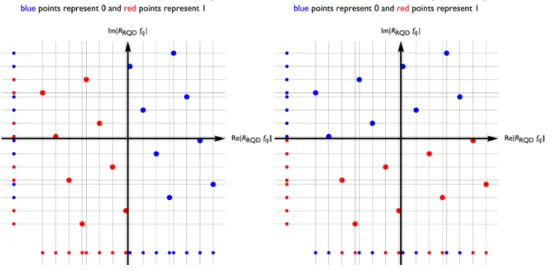
1) Les points de la constellation subissent tout d’abord une rotation d’un angle donné, qui entraîne la corrélation des axes en phase (I) et en quadrature (Q) de la constellation. Les deux composantes I et Q contiennent la totalité de l’information portée par chaque point de la constellation.
2) La composante Q est ensuite retardée par rapport à la composante I avant d’être envoyée sur le canal de transmission.
Les deux composantes I et Q de la constellation originale n’étant pas transmises simultanément, elles subissent des atténuations indépendantes sur le canal. En réception, le processus inverse est appliqué. Lorsqu’une des composantes du symbole de constellation original a été fortement atténuée ou même effacée, le contenu de celui-ci peut être récupéré à grâce à l’autre composante.
Depuis l’invention des turbocodes en 1993, le principe de décodage itératif, encore appelé principe turbo, est utilisé dans de nombreux domaines. Dans la chaîne de communication numérique, le principe turbo a été appliqué à d’autres blocs que les traditionnels décodeurs correcteurs d’erreurs ou égaliseurs. En particulier, l’application d’un processus itératif entre le démappeur et le décodeur LDPC est suggérée dans les directives d’implémentation du standard DVB-T2, afin d’améliorer les performances du système sur les canaux à, notamment lorsque ceux-ci présentent des phénomènes d’effacement.
Notre étude avait pour objectif de concevoir un décodeur BICM pour le standard DVB-T2 mettant en œuvre un processus itératif entre le démappeur et le décodeur et prenant en compte des contraintes de latence et de complexité matérielle. L’étude architecturale a été réalisée en trois phases. Dans un premier temps, nous avons conçu un démappeur de complexité matérielle réduite qui supporte les constellations tournées pour des modulations d’amplitude
en quadrature (QAM) carrées allant jusqu’à l’ordre 256. La seconde étape a consisté à concevoir une architecture de décodeur LDPC adaptée à la mise en œuvre d’un échange d’information itératif avec le démappeur. Enfin, dans la dernière phase, nous avons étudié l’optimisation du séquencement des processus de décodage et de démapping ainsi que la réalisation du récepteur itératif.
Conception d’un démappeur de complexité réduite
Pour une modulation M-QAM non tournée, les informations binaires portées par les composantes I et Q sont indépendantes car la modulation QAM peut être vue comme deux modulations √𝑀-PAM (pulse amplitude modulation) séparées. En réception, le démappeur estime le LLR (Log-Likelihood Ratio) des bits portés par chaque composante en calculant √𝑀 distances euclidiennes sur chacun des axes de la constellation.
Dans le cas d’une constellation M-QAM tournée, le démappeur doit calculer M distances euclidiennes bi-dimensionnelles pour chaque LLR ν :
1 0 2 2 ( ) ( ) exp 2 2 ˆ log ( ) ( ) exp 2 2 i t i t t euc t x i t t euc t x P x D x v P x D x χ χ σ σ π σ σ π ∈ ∈ ⋅ − = ⋅ −
∑
∑
(1) où 2 2 , , ( ) ( I I ) ( Q Q) euc t t d eq t d t d t eq t t a b D x ρ− y − x− ρ y x = − + − (2)L’approximation linéaire communément appliquée pour simplifier l’expression des LLRs lorsque la constellation n’est pas tournée ne peut pas s’appliquer dans ce cas car la rotation introduit une inter-dépendance entre les composantes I et Q. Le calcul des LLRs est plus complexe que dans le cas classique car les deux composantes sont utilisées simultanément. Néanmoins la complexité du démappeur peut être réduite lorsque l’on applique l’approximation dite Max-Log. L’expression des LLRs devient alors :
(
)
(
)
0 1 2 1 ˆ min ( ) min ( ) 2 i i t t i t euc t euc t x x v D x D x χ χ σ ∈ ∈ ≈ − (3)Malgré ces approximations, dans le cas d’une constellation 256-QAM, 256 distances euclidiennes doivent être calculées, ce qui requiert 512 multiplications. La complexité matérielle correspondante peut dans certains cas être rédhibitoire. Afin de réduire le nombre de distances euclidiennes à calculer, nous proposons un algorithme de demapping basé sur la
1. Pour un signal reçu donné, un quart de la constellation (quadrant) est choisi en fonction du signe des composantes I et Q reçue,
2. La sous-région correspondante est dimensionnée de telle sorte que, pour tout point du quadrant sélectionné, celle-ci contienne l’ensemble des points ne différant que d’un bit du point considéré.
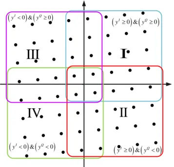
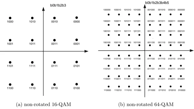
Fig. 1 Les quatre sous-régions utilisées pour la constellation 64-QAM tournée.
La Fig.1 montre la constellation 64-QAM tournée adoptée dans DVB-T2. Chaque point est porteur de six bits. Lorsque les composantes I et Q du signal reçu sont positives, la sous-région sélectionnée est la région bleue. Les trois autres sous-régions correspondent aux trois autres combinaisons de signes possibles. Pour une 64-QAM, le nombre de distances euclidiennes à calculer a ainsi été réduit de 64 à 25. Pour une 256-QAM, il est ramené de 256 à 81.
Outre la diminution du nombre de distances euclidiennes à calculer, nous avons réduit la complexité du calcul de ces distances proprement dites. Le calcul complet d’un terme de distance requiert normalement au moins deux multiplications. Afin de réduire le nombre total de multiplications, nous avons proposé l’application de l’approximation suivante dans l’équation (4) pour le calcul des distances euclidiennes :
(
yI ≥0 &) (
yQ≥0)
(
I 0 &) (
Q 0)
y < y <(
yI ≥0 &) (
yQ<0)
(
I 0 &) (
Q 0)
y < y ≥I
II
IV
III
F(𝑎, 𝑏) = √𝑎2+ 𝑏2 peut être approximé par :
• F(𝑎, 𝑏) = max (𝑎, 𝑏) si min (𝑎, 𝑏) ≤ max (𝑎, 𝑏)/4, sinon • F(𝑎, 𝑏) = max(𝑎, 𝑏) + (min(𝑎, 𝑏) − max (𝑎, 𝑏)/4)/2
L’application simultanée de ces simplifications ont permis la conception d’une architecture flexible de démappeur pour DVB-T2, supportant les constellations QAM tournées et non tournées d’ordre 4, 16, 64 et 256 pour des transmissions sur canaux gaussiens et canaux à fading avec et sans effacements.
Fig. 2 Architecture d’un démappeur DVB-T2 flexible.
Cette architecture est décrite en Fig. 2. Les points de la constellation de deux sous-régions sont stockés dans une mémoire ROM. Les points des deux autres sous-régions sont déduits par symétrie. Chaque bloc élémentaire est chargé du calcul d’une distance euclidienne. Pour une constellation 256-QAM, 9 blocs élémentaires travaillent en parallèle pour calculer les 81 distances euclidiennes. Après 9 cycles de calcul, les 81 distances sont disponibles. Le réseau d’interconnexions est en charge de la sélection des distances nécessaires au calcul de chaque LLR, les deux derniers cycles étant consacrés au calcul des valeurs minimales des distances utilisées dans l’expression (6) puis au résultat de cette même expression.
Ce démappeur a été implémenté sur un FPGA Xilinx Virtex II Pro (XC2VP30). Afin de valider les performances du prototype, un premier démonstrateur matériel a été réalisé : il est constitué en émission d’un générateur pseudo-aléatoire de données sources et d’un mappeur,
Euclidean Distance CMP b0 Network i llr , 1 Q l x− , 1 I l x− ers Constellation Points(ROM) ' I CSI CSIQ' CMP b1 CMP b7 Euclidean Distance ,0 Q l x ,0 I l x ers ' I CSI Q' CSI Euclidean Distance ,7 Q l x ,7 I l x ers ' I CSI Q' CSI ' I eq x Q' eq x I' eq x I' eq x ' Q eq x Q' eq x 7 0 1 7 0 1 Core element Get min Calculate LLR out_cnt out_cnt CMP b0 CMP b1 CMP b7 0 fe fe1 0 0 min eb 1 0 min eb 0 1 min eb 1 1 min eb 0 7 min eb 1 7 min eb
latence du démappeur est égale à 14 périodes d’horloge. Le démappeur implémenté ne requiert que 20 multiplieurs.
Toutes les constellations du standard DVB-T2 ont été vérifiées pour trois modèles de canaux de transmission: canal gaussien, canal de Rayleigh et canal de Rayleigh avec effacements. La Fig.3 compare les courbes de taux d’erreurs binaires résultant d’une part de la simulation en virgule flottante et d’autre part de mesures sur le démonstrateur, pour la transmission d’une constellation 64-QAM sur un canal de Rayleigh avec 15% d’effacements. On observe que les performances du prototype sont quasiment identiques à celles d’un modèle idéal de démappeur bi-dimensionnel.
Fig. 3 Comparaison des taux d’erreurs binaires simulés et mesurés en sortie d’un démappeur 64-QAM pour une transmission sur canal de Rayleigh avec 15% d’effacements.
Afin de faciliter le passage de message entre le décodeur LDPC et le démappeur dans le cadre de la mise en place d’un récepteur itératif, nous avons proposé l’adoption d’un séquencement du décodage LDPC dit VSS (Vertical Shuffled Scheduling). D’autre part, nous avons implémenté la version simplifiée dite min-somme du décodage LDPC VSS. L’architecture correspondante est présentée en Fig. 4.
Au démarrage de l’algorithme, les informations relatives à chaque nœud de parité du graphe de décodage du code LDPC sont initialisées : signe du syndrome, valeur minimale et seconde
0 6 12 18 24 30 Eb/N0(dB) 10- 2 10- 1 100 B ER Simulation, non-rotated Prototype, non-rotated Simulation, rotated Protoype, rotated
valeur minimale des informations provenant des nœuds de variables, ainsi que les indices correspondants. L’ensemble de ces informations sont stockées dans le banc mémoire associé aux nœuds de parités. Puis chaque itération de décodage VSS est constituée de Nldpc sous-itérations exécutées de manière séquentielle. A chaque sous-itération, le processeur de nœud de parité (SISO-B) calcule une information dite extrinsèque qui est envoyée au processeur de nœud de variable (SISO-A). Le processeur de nœud de variable calcule l’information a posteriori en additionnant les LLRs provenant du canal à l’ensemble des informations extrinsèque et en extrait une information a priori qui est renvoyée au processeur de nœud de parité. Enfin le processeur de nœud de parité met à jour les valeurs minimales des informations provenant des nœuds de variable en utilisant les anciennes valeurs et l’information a priori.
Fig.4 Architecture du décodeur LDPC VSS utilisant l’algorithme min-somme.
Lors de la conception du décodeur LDPC pour le standard DVB-T2 nous avons été confrontés à deux problèmes majeurs : des conflits lors de la mise à jour des messages dus à la présence de sous-matrices double-diagonales (DDSM) et des conflits d’accès mémoire dus à l’introduction de niveaux de pipeline. Ces problèmes ont déjà fait l’objet d’études antérieures dans de cas de la conception d’un décodeur à séquencement horizontal, mais pas, à notre connaissance, dans le cas d’un séquencement vertical.
Les matrices de parités des codes LDPC de DVB-T2 présentent un nombre important de DDSMs, dans lesquelles deux ou trois variables interviennent dans chaque relation de parité.
( )t mn E n T Sgn ( ) ( )t mn T ( )t n T 0 1 0 M 1 M 0 index=P α sgn() abs()
α
((1)) sgnTt− Codeword LLR ( )( ) sgn t mn E ( )t mn E ( )( ) sgn t T ( )t T ( (1)) sgnTt− 0, 1 M M 0 1 , P P ( ) sgn Tmn 0 1 0 1 index M M P P index ( )t T (t1) α − 0 1 0 1 update M M P Pα FIFO FIFO 0 1 0 1 0 1 init init init LLR MAX 1 SISO-B SISO-Acause un conflit d’accès mémoire. Le partitionnement de la matrice s’avère être une technique efficace pour réduire le nombre de DDSMs. Il ne peut néanmoins assurer la suppression de la totalité des DDSMs dans la matrice de parité. Pour résoudre le problème de conflit dans les DDSMs résiduelles, nous avons proposé de réutiliser l’information mise à jour de la première diagonale et de de renvoyer le résultat intermédiaire en tant qu’entrée pour le processus de mise à jour de la seconde diagonale. La Fig. 5 décrit le schéma logique correspondant à la mise à jour du signe d’une DDSM.
Fig. 5 Schéma logique pour la mise à jour du signe d’une DDSM.
Afin d’augmenter la fréquence maximale de fonctionnement du circuit et le débit des données en sortie du décodeur, des techniques classiques de pipelinage sont appliquées. Le séquencement du pipeline. Il se peut alors qu’une sous-itération démarre avant la fin de la précédente et qu’une information relative au nœud de parité soit lue avant d’être mise à jour. Des conflits peuvent en découler qui dégradent les performances de décodage. Un séquencement élaboré doit par conséquent être mis en place pour éviter ce type de conflits. Nous avons proposé une méthode de modification du séquencement pour le décodage VSS. Il s’agit tout d’abord de détecter les cas de conflit et de modifier l’ordre de traitement des nœuds de parité dans une sous-itération. Puis la sous-matrice est partitionnée, la plupart des conflits étant supprimés lors de cette étape. Pour les cas problématiques résiduels, l’ordre de traitement des nœuds de variable est modifié avant de pouvoir décider de l’information décodée. Cette technique n’engendre quasiment aucun cycle d’attente entre les sous-itérations, ce qui se traduit par une augmentation conséquente du débit de décodage.
α
( 1) sgn t T − ( ) sgn t mn E ( ) sgnT t ' α 0 1 'α
Check node memory bank
0
1
1
second diagonal
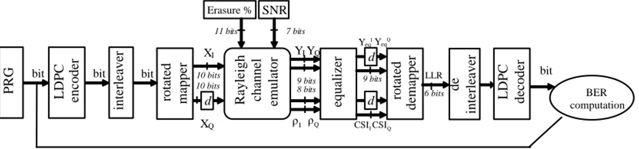
Fig. 6 Schéma-bloc de la chaîne de transmission DVB-T2 simplifiée.
Une chaîne de transmission DVB-T2 simplifiée, constituée d’une source numérique, un modulateur BICM, un émulateur de canal et un démodulateur BICM a été implémentée sur un FPGA Xilinx Virtex 7 sur la plateforme montrée en Fig. 7.
Fig.7 Plate-forme matérielle implémentant la chaîne de transmission DVB-T2 simplifiée.
L’utilisation des ressources du FPGA pour le décodeur LDPC sont listées dans la Table 1. Le décodeur fonctionne à une fréquence de 113MHz, correspondant à un débit utile en sortie du décodeur égal à 151 Mbit/s dans le cas d’un code de longueur 64k, de rendement 4/5 et pour 15 itérations de décodage VSS.
XC5VLX330 Flip-Flops LUTs RAMs
Décodeur LDPC 18,029 (8%) 41,032 (19%) 84 (29%)
Table 1 Utilisation des ressources matérielles du FPGA pour la réalisation du décodeur LDPC.
rotated mapper Rayleigh channel emulator
XI XQ bit SNR Erasure % BER computation YI YQ 10 bits 11 bits 7 bits equalizer YeqIYeqQ 9 bits rotated dem apper d d d bit PRG LDPC encoder interleaver bit 9 bits 8 bits LDPC decoder bit 6 bits LLR I ρ ρQ CSIICSIQ 10 bits de interleaver
mesures effectuées sur le prototype et les simulations en virgule fixe réalisées à partir d’une description en langage C du décodeur, pour le code 64k de rendement 4/5, sur canal de Rayleigh avec 15% d’effacements. Les courbes de la Fig. 8 ont été obtenues avec des constellations QAM conventionnelles (non-tournées) tandis que la Fig. 9 montre les performances avec constellations tournées.
Le démappeur et le décodeur ont également été intégrés sur le démonstrateur de démodulation DVB-T2 montré en Fig. 10, fourni par Teamcast dans le cadre du projet Eurêka/Eurostars SME42 (SMEs for T2). Les performances du démodulateur intégrant notre démappeur et décodeur ont été mesurées pour différents rendements de codage et constellations et ont permis de valider les algorithmes et architectures proposées.
Fig.8 Performances comparées du prototype et du modèle C du décodeur BICM avec QAM non tournées pour une transmission sur canal à fading avec 15% d’effacements.
5 1 0 1 5 2 0 2 5 3 0 3 5 Eb/N0(dB) 1 0-3 1 0-2 1 0-1 1 0-4 1 0-5 1 0-6 1 0-7 1 0-8 1 0-9 BE R Prototype QPSK Simulation fix QPSK Prototype 16-QAM Simulation fix 16-QAM Prototype 64-QAM Simulation fix 64-QAM Prototype 256-QAM Simulation fix 256-QAM
Fig.9 Performances comparées du prototype et du modèle C du décodeur BICM avec QAM tournées pour une transmission sur canal à fading avec 15% d’effacements.
L’introduction d’un processus itératif entre le décodeur LDPC et le démappeur permet d’améliorer les performances du décodeur BICM et/ou de diminuer le nombre d’itérations nécessaires à sa convergence. Néanmoins, la conception d’un récepteur itératif de faible latence et de complexité raisonnable présente des difficultés. En particulier, la latence constitue la contrainte principale. Elle est liée à deux causes dans le cas d’une architecture BICM conventionnelle : la présence de l’entrelacement et le désentrelacement binaire d’une part et le séquencement horizontal classiquement utilisé pour le décodage LDPC.
Fig.10 Plate-forme de modulation/démodulation DVB-T2 de Teamcast utilisée dans le cadre du projet SME42. 5 1 0 1 5 2 0 2 5 3 0 3 5 Eb/N0(dB) 1 0-3 1 0-2 1 0-1 1 0-4 1 0-5 1 0-6 1 0-7 1 0-8 BE R Prototype QPSK Simulation fix QPSK Prototype 16-QAM Simulation fix 16-QAM Prototype 64-QAM Simulation fix 64-QAM Prototype fix 256-QAM Simulation fix 256-QAM
RAM dédiée à l’entrelacement et au désentrelacement par des look-up tables pour permettre un routage rapide de l’information, puis nous avons adopté le séquencement de décodage LDPC vertical VSS précédemment étudié fin de garantir une génération rapide de l’information extrinsèque.
Fig. 11 Structure d’un récepteur itératif
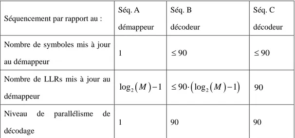
Le passage de message lors du décodage VSS est réalisé colonne par colonne ; l’information extrinsèque et les LLRs peuvent ainsi être échangés entre le démappeur et le décodeur en un nombre de cycles limité. Plusieurs séquencements d’échange de messages peuvent être considérés, basés sur différentes stratégies de combinaison du parallélisme et de mise à jour des LLRs. Trois séquencements de référence ont été étudiés et sont listés dans la Table 2.
Séquencement par rapport au :
Séq. A démappeur Séq. B décodeur Séq. C décodeur Nombre de symboles mis à jour
au démappeur
1 ≤90 ≤90
Nombre de LLRs mis à jour au démappeur
( )
2log
M
−
1
≤
90 log
⋅
(
2( )
M
−
1
)
90 Niveau de parallélisme de décodage 1 90 90Table 2 Les trois séquencements étudiés pour les échanges de messages entre le décodeur LDPC et le démappeur.
QAM
demapper Bit de-interleaver
y
u
( ; )i P v o ( ; )i P c I 1π
− I-Component Q-Component delay{
( ; )i P u oπ
( ; )i P v I ( ; ) i P c o LDPC decoder Bit interleaverπ
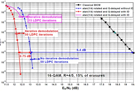
Nous avons dans un premier temps implémenté le récepteur itératif pour la constellation QPSK. Deux prototypes ont été réalisés, basés sur le séquencement C. Le premier prototype utilise l’algorithme de décodage VSS min-somme (MS) tandis que le second met en œuvre l’algorithme VSS min-somme-3 (MS3), dont les performances sont plus proches de celles de l’algorithme de référence somme-produit. Les ressources matérielles utilisées pour les deux décodeurs BICM itératifs (BICM-ID) sont recensées dans la Table 3. La fréquence maximale de fonctionnement du décodeur BICM-ID MS est égale à 80 MHz après placement-routage, ce qui correspond à un débit de 107 Mbit/s en sortie du décodeur LDPC pour un rendement de codage de 4/5 et 15 itérations de décodage VSS.
XC5VLX330 Flip-Flops LUTs RAMs
BICM-ID MS 23,118 (11%) 9,3130 (44%) 179 (62%) BICM-ID MS3 26,088 (14%) 10,8126 (51%) 193 (67%) Coût additionnel
(MS MS3)
2970 (3%) 14996 (7%) 14 (5%)
Table 3 Utilisation des ressources matérielles FPGA la conception d’un décodeur BICM itératif.
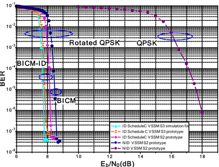
Fig. 12 Courbes de performance d’un décodeur BICM-ID QPSK sur canal à fading avec 15% d’effacements. Code LDPC 64k de rendement 4/5.
6 8 1 0 1 2 1 4 1 6 1 8 Eb/N0(dB) 1 0-3 1 0-2 1 0-1 1 0-4 1 0-5 1 0-6 1 0-7 1 0-8 BE R
ID ScheduleC VSSM S3 simulation fix ID Schedule C VSSM S3 prototype ID ScheduleC VSSM S2 prototype NID VSSM S2 prototype NID VSSM S2 prototype BICM QPSK Rotated QPSK BICM-ID
code 64K et rendement de codage 4/5 pour une transmission sur un canal à fading avec 15% d’effacement. Les résultats sont présentés en Fig. 12. Le gain liée à la diversité de constellation est de l’ordre de 10 dB tandis le gain additionnel lié au processus itératif est égal à 0,5 dB pour l’algorithme MS et 0,8 dB pour l’algorithme MS3. Les performances mesurées sont quasiment identiques aux courbes de référence simulées en virgule fixe. A notre connaissance, il s’agit du premier prototype de décodeur BICM-ID DVB-T2 référencé dans la littérature.
La suite de ces travaux va essentiellement consister à étendre cette dernière étude aux cas des constellations d’ordres supérieurs : 16-QAM, 64-QAM et 256-QAM.
CHAPTER
1
Background
The second generation of terrestrial video broadcasting standard (DVB-T2) was defined in 2008. The key motivation for the second generation is to provide high capacity and robust transmission to fixed, portable and mobile terminals. One of the important key technologies in DVB-T2 is the advanced Bit-Interleaved Coded Modulation (BICM) with Signal Space Diversity (SSD). The possibility of iteration between the decoder and demapper further increases the performance gain especially over a deep faded channel.
In this chapter we start with a brief introduction of the digital communication system, then we offer a review of different Forward Error Correction (FEC) codes. The fading channel model used in the test of our study is represented next. It is followed by a review of the existing different schemes of the coded modulation. Afterwards, we give a brief introduction of the DVB-T2 system and a detailed description of BICM with Signal Space Diversity (BICM-SSD) and BICM with Signal Space Diversity and iterative process (BICM-ID-(BICM-SSD). In the remaining section, we give a detailed introduction of the LDPC codes adopted in DVB-T2 system, including the encoding method and the property of the codes.
1.1
A digital communication system
The functional diagram and basic elements of a digital communication system is illustrated in Fig. 1.1. In a digital communication system, the source may be either analog or digital signal. The messages produced by the source are converted into digital sequence. To have an efficient communication, we seek efficient representation of the source information that results in little or no redundancy. The process of efficiency converting the source into a sequence of binary digits is called source encoding or data compression.
To have a reliable communication system, the channel encoder induces some redundancy in a controlled manner. The redundancy can be used at the receiver to overcome the effects of noise and interference encountered in the transmission of the signal through the channel. The encoding involves taking k information bits at a time and mapping each k-bit sequence into a unique n-bit sequence, which is called a codeword. The ratio k/n is called code rate.
The modulator serves as the interface for the channel encoder to the communication channel. It maps the binary information sequence into a continuous-time electrical signals (waveforms). Let us suppose that the modulator may transmit b coded information bits at the same time t by using one waveform of the set of M = 2b distinct waveforms, s
i(t), i = 0, 1, · · · , M − 1. We call this M -ary modulation (M > 2,M=2 binary modulation).
The communication channel is the physical medium that is used to send the signal from the transmitter to the receiver. The channel may be the atmosphere, wire lines, optical fiber cables, ect. Whatever the physical medium used for the transmission of the information, the essential feature is that the transmitted signal may get corrupted and induced errors.
At the receiving end of a digital communication system, the demodulator processes the channel-corrupted transmitted waveform and reduces the waveforms to a sequence that rep-resents estimates of the transmitted data symbols. This sequence is passed to the channel decoder, which attempts to reconstruct the original information sequence. The average prob-ability of a bit-error at the output of the decoder is a measurement of the performance of the combination of the demodulator and the decoder, which is a function of the code character-istic, the type of the waveform of the modulator, the transmitter power, the characteristic of the channel and the demodulation and decoding algorithms. Finally, the source decoder attempts to reconstruct the original signal by processing the output of the channel decoder based on the knowledge of the source encoding method.
1.2
Error control codes
Error control codes also called Forward Error Correction (FEC) enable the detection and correction of the errors introduced by transmission of a modulated signal through a channel.
1.2. ERROR CONTROL CODES 7 Digital Modulator Digital demodulator Source encoder Source decoder Channel encoder Channel decoder Channel Information source Output transducer
Figure 1.1 — Basic elements of digital communication system
Today’s error correction codes fall into two categories: block codes and convolutional codes. However, Turbo codes and Low density parity check (LDPC) codes could be classified as a new branch of error control codes: the iteratively decoded codes.
1.2.1 Linear block codes
A binary block code generates a block of n coded bits from k information bits, we call this as an (n, k) binary block code, with (n − k) parity bits. Hamming (7,4) code is a famous binary block code that encodes 4 bits of data into 7 bits by adding 3 parity bits. The linear block codes are encoded by C = U × G. For an (n, k) code with k information bits, denoted as: U= [u1, u2, · · · , uk], are encoded into the codeword, denoted as C = [c1, c2, · · · , cn]. Gk×nis the generator matrix and for a systematic linear block code, the generator matrix is described as Gk×n = [Ik×k|Pk×(n−k)], where Ik×k is the k × k identity matrix and Pk×(n−k) matrix determines the parity bits.
Gk×n= g11 g12 · · · g1n g21 g22 · · · g2n .. . ... . .. ... gk1 gk2 · · · gkn (1.1) Gk×n= [Ik×k|Pk×(n−k)] = 1 0 · · · 0 g11 g12 · · · g1(n−k) 0 1 · · · 0 g21 g22 · · · g2(n−k) .. . ... . .. ... ... ... . .. ... 0 0 · · · 1 gk1 gk2 · · · gk(n−k) (1.2)
The parity check matrix is used to decode linear block codes. The parity check matrix corresponding to the generator matrix Gk×n = [Ik×k|Pk×(n−k)] is defined as: H(n−k)×n = [I(n−k)×k|P(n−k)×(n−k)]. It is easy to verify that G × H>= 0
we can get C × H>= 0k×(n−k). Thus, multiplication of any valid codeword with the parity check matrix results in all-zero vector, this is called syndrome testing and is used to determine the valid codeword.
One powerful class of block codes is the Bose-Chadhui-Hocquenghem (BCH) codes, which were invented in 1959 by Hocquenghem, and independently in 1960 by Bose and Ray-Chaudhuri [3]. BCH codes are polynomial codes over a finite field with a particularly chosen generator polynomial, so it provides a large selection of block length. The BCH codes are cyclic codes, in which the high rates BCH codes typically outperform all other block codes with the same n and k at moderate to high SNRs.
Reed-Solomon (RS) codes, which are non-binary BCH codes, with symbols as coefficients of a polynomial p(x) over a finite field GF (q), (q > 2), invented by Irving S. Reed [9] and Gustave Solomon. Reed-Solomon codes achieve a minimum distance of dmin = N − K + 1, which is the largest possible minimum distance between codewords for any linear code (n, k). The RS(204,188) based on GF (28) shortened from RS(255, 239), is the RS codes adopted in the DVB-T standard with the generator polynomial p(x) = 1 + x2+ x3+ x4+ x8. Berlekamp-Massey decoding algorithm is the most popular hard decision decoding algorithm for BCH and RS codes, which was discovered by Elwyn Berlekamp [10] and James Massey [11]. While Chase-Pyndiah algorithm [12] is a soft input soft output decoding algorithm well used in the turbo decoding of product codes composed of BCH or Reed-Solomon component codes.
1.2.2 Convolutional codes
Convolutional codes differ from block codes in that the encoder contains memory so the out-put of the encoder at any given time is not only determined by the inout-put but also by the previous memorized inputs. Convolutional codes are commonly specified by three parame-ters (n, k, m), where n is the number of output bits, k is the number of input bits and m is the number of memory registers. The octal generated polynomial is also used for defining a convolutional code. The constrain length K = k · (m − 1) represents the number of bits in the encoder memory that affect the generation of the n output bits, The code in Fig. 1.2 is a (3, 1, 3) convolutional code, with a code rate of R=1/3 and the constrain length as 2. Viterbi [13] in 1967 proposed a maximum likelihood (ML) decoding algorithm that was relatively easy to implement for soft-decision decoding of the convolutional codes. In 1974, Bahl, Coke, Jelinek and Raviv (BCJR) [14] introduced a maximum a posteriori probability (MAP) decod-ing algorithm for convolutional codes with unequal a prior probability for the information bits. The BCJR has been widely applied to soft-decision iterative decoding scheme in which the a prior probability information changes from iteration to iteration.
1.2. ERROR CONTROL CODES 9
Figure 1.2 — A (3,1,3) convolutional code
1.2.3 Concatenated codes
Concatenated codes form a class of error-correcting codes that are derived by combining an inner code and an outer code. They were conceived in 1966 by Dave Forney [15] as a solution for the problem of finding a code that has an exponentially decreasing error probability with increasing block length and a polynomial-time decoding complexity. The inner code is typi-cally designed to remove most of the errors introduced by the channel and the outer code is typically a less powerful code that further reduces error probability when the received bits have a relatively low error probability. The concatenated codes frequently have the inner and outer codes separated by an interleaver to break up bursts of errors. In the DVB-T stan-dard, the inner code is a punctured convolutional code with five code rates 1/2, 2/3, 3/4, 5/6, and 7/8. The Viterbi decoder tends to have some residual errors in bursts. The punctured Reed-Solomon (204,188) as the outer code has good burst error correcting properties. The combination of the inner code with outer code plus interleaver can achieve very low error probability. Digital Modulator Digital demodulator Source encoder Source decoder Channel encoder Channel decoder Channel Information source Output transducer Interleaver De-interleaver Reed Solmon (204,188) RS decoder Channel Convolutional code Viterb decoder
Figure 1.3 — The FEC of DVB-T standard
1.2.4 Turbo codes
Shannon set out the performance limits of channel coding and modulation schemes as early as 1948 [16] [17], however he gave no indication on how to construct good practical codes. The achievement of the Shannon capacity limit has been the goal of channel coding theorists
ever since. However the performance of the mentioned Reed-Solomon codes, convolutional codes, product codes and concatenated codes is still a long way from the Shannon limit. Turbo codes, invented by Berrou and Glavieux [5] in 1993, is the first codes that are capable of approaching Shannon’s limit.
These codes involve a parallel concatenation of two recursive systematic convolutional (RSC) codes. A general structure of a turbo encoder is shown in Fig. 1.4. Two component codes are used for encoding the same input bits m, but an interleaver is placed between the encoders. The output of the encoder is (m, X1, X2) for a code rate of R=1/3. Higher code rates are obtained by puncturing.
Encoder1 Interleaver Encoder2 Data source m X1 X2 X=(m,X1,X2) Interleaver Interleaver De-interleaver De-interleaver R0 R0 R1 R2 priors extrinsic extrinsic priors Decoder 2 Decoder 2
Figure 1.4 — A classical structure of Turbo encoder
Fig. 1.5 shows a general structure of Turbo decoder. Two component decoders are linked by interleavers in a structure similar to that of the encoder. The inputs of the decoder are multiplexed as (R0, R1, R2), according to the systemic bit and the other two parity bits. Each decoder takes three inputs: the systematic bit, the parity bit transmitted from the corresponding component encoder and the information from the other component decoder, which is referred to as a priori information. Each decoder needs to provide the probability of the decoded bit sequence, so a Soft Input Soft Output (SISO) decoding algorithm is required. BCJR-based decoding and Max-Log MAP decoding represent two classical decoding algo-rithms for Turbo codes. A soft output version of the Viterbi decoding (SOVA) is also a wide spread decoding algorithm for these concatenated codes. During the decoding process, each decoder alternately builds upon the results of the other to gradually enhance the reliability of the decisions via the exchange of extrinsic information on the systematic bits.
1.2.5 Low density parity check codes
Low density parity check (LDPC) codes were originally invented by Gallager [2] in 1963. However, these codes were ignored until the introduction of turbo codes or more precisely iterative decoding. LDPC codes were re-born by Mackay and Neal [6] in 1997.
1.3. THE FADING CHANNEL MODEL 11 Encoder1 Interleaver Encoder2 Data source m X1 X2 X=(m,X1,X2) Interleaver Interleaver De-interleaver De-interleaver R0 R0 R1 R2 priors extrinsic extrinsic priors Decoder 2 Decoder 1
Figure 1.5 — A structure of Turbo decoder
These codes are linear block codes based on simple parity check equations and specified by a sparse parity-check matrix containing mostly zeros and a few ones (hence low density). They are often represented as bipartite graphs (Tanner Graphs) [18] which contain loops or cycles. An LDPC code is said to be regular if the check node and bit node degrees are constant and irregular if they are not. The degree correspond to the number of ones in the rows (for check nodes) or columns (for bit nodes) of the parity check matrix.
The widely used decoding algorithm is Belief Propagation (BP) also named as Message Passing (MP), since the messages are passed between the check nodes and bit nodes through the connection defined by the parity check matrix. A well-known instance of BP is the sum-product algorithm first proposed by Gallager in [2], which may also be realized in the log domain. The method to simplify the check node process were well studied by Chen and Fossorier [19]. Among them normalized min-sum is mostly used in current LDPC decoders. Different ways of scheduling the bit and check node update can have a significant impact on the convergence speed of the decoding process. The default approach used in classical BP is called flooding with two phase, where all of the bit nodes are updated in parallel followed by the update of all the check nodes. Faster convergence can be achieved with shuffled scheduling [20] [21]. A detailed explanation of the decoding algorithm and scheduling will be presented in Chapter 3.
1.3
The fading channel model
The communication channel represents a physical medium between the transmitter and the receiver. The channel model is a representation of the input-output relationship in mathe-matical or algorithmic form. Unlike wired channels whose characteristics are stationary and predictable, wireless channels are not predictable. They introduce significant levels of inter-ference, distortion, and noise. Modelling wireless channels has been one of the most difficult parts in the wireless system design.
1.3.1 General description of fading channel
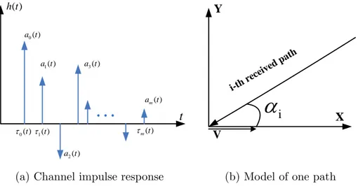
Developing mathematical models for the propagation of signals over a transmission medium requires a good understanding of the underlying physical phenomena. In wireless mobile communications, the electromagnetic waves often do not directly reach the receiver because of the obstacles that block the Line Of Sight (LOS) path, such as buildings, mountains or foliage. A signal travels from transmitter to receiver over multiple reflective paths; this phenomenon is called multipath propagation. This effect can cause fluctuations in the received signal’s amplitude, phase and angle of arrival, which can be constructive or destructive. A typical scenario of mobile radio communications is shown in Fig. 1.6, where the three main mechanisms that impact the signal propagation are depicted.
3 causes fluctuations in the receiver signal’s amplitude and phase. The sum of the signals can be constructive or destructive. A typical scenario of mobile radio communications is shown in Fig. 1, where the three main mechanisms that impact the signal propagation are depicted [1.9].
Fig. 1. A typical scenario of mobile radio communications
Those mechanisms are:
• Reflection. It occurs when the electromagnetic wave bumps against a smooth surface, whose dimensions are large compared with the signal wavelength.
• Diffraction. When a building whose dimensions are larger than the signal wavelength obstructs a path between transmitter and receiver, new secondary waves are generated. This phenomenon is often called shadowing, because the diffracted field can reach the receiver even when shadowed by an impenetrable obstruction (no line of sight).
• Scattering. It happens when a radio wave bumps against a rough surface whose dimensions are equal to or smaller than the signal wavelength. In the urban area, typical obstacles that cause scattering are lampposts, street signs, and foliage.
Another negative influence on the characteristics of the radio channels is the Doppler effect, due to the motion of the mobile station. The Doppler effect causes a frequency shift of each portion of transmitted waves [1.10]. Relation (1.1) gives the Doppler frequency of the incident wave:
! f = fmaxcos" , (1) where ! fmax= v c0 f0 (2)
is the maximum Doppler frequency or shift, which depends on the ratio of the speed of the vehicle (
!
v ), the speed of the light (
!
co), and the carried frequency (
!
fo);
!
" is the angle of arrival of the incident wave (Fig. 2) with respect to the mobile velocity vector [1.11, 1.12].
Fig. 2. Angle of arrival of the n-th incident wave
Figure 1.6 — A typical scenario of mobile radio communications
Those mechanisms are: 1.) Reflection. It occurs when the electromagnetic wave bumps against a smooth surface, whose dimensions are large compared to the signal wavelength. 2.) Diffraction. When a building whose dimensions are larger than the signal wavelength obstructs a path between transmitter and receiver, new secondary waves are generated. This phenomenon is often called shadowing, because the diffracted field can reach the receiver even when shadowed by an impenetrable obstruction. 3.) Scattering. It happens when a radio wave bumps against a rough surface whose dimensions are equal to or smaller than the signal wavelength. In the urban area, lampposts, street signs, and foliage are typical obstacles that cause scattering. Another negative influence on the characteristics of the radio channels is the Doppler effect, due to the motion of the mobile receiver. The Doppler effect causes a frequency shift of each portion of transmitted waves, as described in equ. (1.3).
f = fmax· cos α (1.3)
1.3. THE FADING CHANNEL MODEL 13
on the ration of the speed of the receiver v, the speed of the light c0and the carrier frequency f0. α is the angle of the arrival of the wave with respect to the mobile receiver.
Fading channel
Large-scale fading due to motion over large areas
Small-scale fading due to small changes in position
Time spreading (dispertion) Time variance of the channel Time delay domain description Frequency domain description Frequency selective fading Flat fading Frequency selective fading Flat fading Time domain description Doppler shift domain description fast fading slow fading fast fading slow fading Fourier transforms Fourier transforms
Figure 1.7 — Fading types and their corresponding manifestation
Fig. 1.7 represents an overview of the manifestation of a fading channel [22] [23]. It falls into two main categories: large-scale fading and small-scale fading. Large-scale fading represents the average signal power attenuation or path loss due to motion over large areas. This phenomenon is affected by prominent terrain contours (hills, forests, clumps of buildings, etc) between the transmitter and the receiver. The signal suffered large-scale fading is said to be shadowed by these obstacles. The amplitude change caused by shadowing is often modelled by a log-normal distribution with a standard deviation according to the log-distance path loss.
Small-scale fading refers to the dramatic changes in signal amplitude and phase that can be experienced as a result of small changes (as small as half-wavelength) between the receiver and transmitter. If the multiple reflective paths are large in number and there is no line-of-sight signal component, the envelope of the received signal is statistically described by a Rayleigh probability distribution function (pdf). When there is a dominant non-faded signal component, such as a line-of-sight propagation path, the small-scale fading envelope is described by a Rician pdf. The small-scale fading manifests itself into two distinct mechanisms, namely, time spreading of the signal and time variance of the channel. The former one is due to multipath and the later one is due to motion.
Frequency selective fading and Flat fading are the two kinds of fading in the signal dis-persion manifestation,which could get explained both in time domain and frequency domain. From time domain point of view, frequency selective fading occurs when the multipath delay spread is greater than the duration of symbol. The frequency selective fading is also known as Intersymbol Interference (ISI), which leads to an irreducible BER degradation. From the