HAL Id: hal-01792392
https://hal.archives-ouvertes.fr/hal-01792392
Submitted on 15 May 2018HAL is a multi-disciplinary open access archive for the deposit and dissemination of sci-entific research documents, whether they are pub-lished or not. The documents may come from teaching and research institutions in France or abroad, or from public or private research centers.
L’archive ouverte pluridisciplinaire HAL, est destinée au dépôt et à la diffusion de documents scientifiques de niveau recherche, publiés ou non, émanant des établissements d’enseignement et de recherche français ou étrangers, des laboratoires publics ou privés.
First steps towards design, simulation, modelling and
fabrication of electrostatic micromotors
Yvan Lefèvre, Michel Lajoie-Mazenc, Emmanuel Sarraute, Henri Camon
To cite this version:
Yvan Lefèvre, Michel Lajoie-Mazenc, Emmanuel Sarraute, Henri Camon. First steps towards design, simulation, modelling and fabrication of electrostatic micromotors. Sensors and Actuators A: Physical , Elsevier, 1995, 47 (1 - 3), pp. 645-648. �10.1016/0924-4247(94)00979-R�. �hal-01792392�
O
pen
A
rchive
T
OULOUSE
A
rchive
O
uverte (
OATAO
)
OATAO is an open access repository that collects the work of Toulouse researchers and makes it freely available over the web where possible.
This is an author-deposited version published in : http://oatao.univ-toulouse.fr/ Eprints ID : 19943
To link to this article : DOI: 10.1016/0924-4247(94)00979-R URL : https://doi.org/10.1016/0924-4247(94)00979-R
To cite this version : Lefèvre, Yvan and Lajoie-Mazenc, Michel and Sarraute, Emmanuel and Camon, Henri First steps towards design, simulation, modelling and fabrication of electrostatic micromotors. (1995) Sensors and Actuators A: Physical, vol. 47 (n° 1 - 3). pp. 645-648. ISSN 0924-4247
Any correspondence concerning this service should be sent to the repository administrator: [email protected]
First steps towards design, simulation, modelling and fabrication
of electrostatic micromotors
Y. Lefèvre
a,M. Lajofo-Mazenc
a,E. Sarraute
b,H. Camon
c a LEE!, URA CNRS n° 847, 2 rue C. Camichel, 31071 Toulouse Cedex, Franceb LESlR, URA CNRS n° Dl375, 61 avenue du Président Wilson, 94235 Cachan, France
c LAAS/CNRS, 7 avenue du colonel Roche, 31077 Toulouse Cedex, France
Abstract
Following the principles proposed by workers at Berkeley University, we have developed a version of the electrostatic micromotor based on the sacrificial layer method combined with oxidation of the rotor. In_ ord_er to study the behaviour of this electrostatic micromotor, we have elaborated Iwo softwares. The first, called EFCREL, is to sjmulate the static operation of the electrostatic micromotors and the second, called EFDYN, is to simulate their dynamic oper;i.tion. Both are based on a finite-element code, called EFCAD, for electromagnetic field computation. They help us with the design of the fabricated micromotor and the simulation of its dynamic working, respectively. The elaboration of these two softwares represents our first steps towards a fully integrated CAD (computer aided design) system for microrriotor�.
Keywords: Computer-aided design; Electrostatic micromotors
1. Introduction
The principles of design, fabrication and operation of electric micromotors have been investigated in recent years [1,2]. This paper discusses our experience of related issues.
Before manufacturing a micromotor, we have to design it. The design procedure has several stages. At each stage design tools are needed, for example: op timization of the main dimensions, optimization of the electromechanical structure, mask design, semiconduc tor process simulation, mechanical structure and ma terials modelling. The final goal is a CAD (computer aided design) integration that involves a continuous computerized chain from the design to the finished product, but this is difficult to achieve. Currently various CAD tools are used independently of one another.
This paper describes our first steps towards the design of a micromotor and is devoted to electromechanical modelling and design that can be implemented in a CAD procedure. Two CAD tools are presented. One is devoted to the design of the electromechanical struc ture and the other is devoted to the design of the electric or electronic supply. Both are linked to an electric field computation code. The first one, described in Section 2, is based on a simulation procedure of
the static behaviour of an electric micromotor. It helps us to design an electrostatic micromotor. This micro motor has been fabricated and a brief description is given. Section 3 describes the second tool, which is based on a simulation of the dynamic behaviour of an electric motor. This second tool is applied to the study of the dynamic behaviour of the micromotor.
2. Simulation of the static behaviour
Preliminary design using simple analytical expressions of the main electromechanical quantities, such as torque and flux, gives roughly the main dimensions of the machine (air-gap value, radius of the rotor, etc.). Then other parameters like the number of electrodes, the number of poles and the shape of electrodes must be determined. To make the optimum choice, designers must study for eacb set of these parameters the per formance of the motor under design. At this stage of the design procedure, electromechanical quantities that characterize its electromechanical behaviour must be defined. Analogies from the classical magnetic electrical motor can be useful. The comparison between electric field and magnetic field formulations in a 2D finite element code has been studied [3]. The results of this
study show that with minor changes, a 2D finite-element code devoted to classical magnetic machines can be used. These codes have been much improved and are very well adapted to the analysis of electrical machines. In particular,. we have used methods that allow the characteristic quantities to be calculated taking into account the movement of the rotor [4]. For an electric motor these quantities are the electric driving torque, the coefficients of capacitance of each electrode and the coefficients of induction between two electrodes. These quantities are qualified as static because they are computed as a function of the rotor position. Modules that can calculate these quantities have been implemented in a 2D finite-element code called EFCAD [3].
For example, the static operation of an electric mi cromotor bas been simulated. Fig. 1 shows the scalar equipotential lines in the micromotor when only one phase of the stator is supplied. Fig. 2 shows the electric driving torque versus rotor position due to two phases. Many other electrical structures of micromotor have been simulated [5]. The results obtained allow us to choose a motor design. This micromotor, which is shown in Fig. 3, is a three-phase radial-gap variable-capacitance motor with a stator poles number to rotor pales number ratio of 3/1. The geometrical dimensions are 120 µm
Fig. 1. Scalar equipotential lines of a 3/1 electric micromotor.
Xi0-16 [Nm/v·2] 0.5 ,,,---.... 0.0 \ 0 20 \ ( 1 1 1 \ .,
:
,\ I ' ' \ 40 , , ' ' 1 / [degrees] 60Fig. 2. Electric driving torque vs. rotor position when two stator phases are supplied.
Fig. 3. Side view of the fnbricatcd micromotor.
diameter, 4 µm air gap and 1.5 µm thickness. The number of rotor poles is six with an angular width of 18° and an angular pitch of 60°. The stator pole angular width is 16° with 4° separation between the stator pales. Following the principles proposed by workers at Berkeley University, the fabrication is based on the surface micromachining technique, which means a pro cess for depositing and etching multiple layers of sac rificial and structural thin films to build complex mi crostructures [6,7]. The material set from which the micromotor is fabricated consists of four basic elements: polycrystalline silicon doped with phosphorus, which serves as the conducting material, silicon nitride, which serves as the insulating structural materîal, silicon oxide, which serves as an insulating layer as wcll as a sacrificial layer and spin on glass (SOG), which only serves as a sacrificial layer. At this stage, the technological process bas been carried out successfully and stepping motion bas been demonstrated. Fig. 3 shows a photograph of the micromotor.
These examples show what kind of studies can be done with such a tool. It can be easily employed in a design procedure and can be linked to other CAD tools, like mask design. Since mcshing can be done automatically, all the simulation procedure can be pil oted by a superviser in which parametric programming can be implemented.
3. Simulation of the dynamic bchaviour
After a micromotor design bas been chosen, its dynamic operation must be analyscd .
3.1. Electromechanical mode/
The dynamic bchaviour of the variable-capacitance micromotors can be modellcd by the diffcrential matrix
equations [8]:
!
[Q(r)J = [Rr 1[vcr)J- [Rr 1[cc acr))r 1[Q(r)J!
û(t) ={T,(t)-Bû(t)-(C1 +CP])sign(û(t})}/1 d dt 0(t) = û(t) (1)The first equation governs the electrical beh.aviour of the motor. The currents, which are equal to the de rivative versus time of the charges on the electrodes [Q(t)], are related to the external supply voltages [V(t)] by the diagonal matrix of resistance [R] and the matrix of influence and capacitance coefficients [C(0(t))]. The two last equations describe the motion of the rotor. ü(t) is the angular speed of the rotor and 0(t) the angular position of the rotor. The rotor is submitted to the electrical torque Te(t), the viscous and diy friction torques. The electrical torque Te(t) is calculated by the angular derivation of the electrical co-energy of the system:
1
a
Te(t)=
2
[U(t) ]t ae [ C( 0(t)) ][ U(t)] (2)where [U(t)] is the potential vector on each electrode of the machine. B is the viscous friction coefficient. The dry friction torque depends on two coefficients. The constant term C1 takes into account the rotor weight. The term C2Us 2 takes into account the axial and radial efforts, which are functions of the square of the potential applied on the stator electrodes. J is the inertial coefficient.
3.2. Computation of the electrical parameters
The matrix of resistances [R] is constant and can be easily guessed from the physical and geometrical
char-x 10-15 [Fl0.6 0.5 0.4 0.3
Fig. 4. Coefficient of capacitance of one phase of the :;tator.
100 50 0 2000 [degrees] 1000 0 -1000 0.000 0.001 x10⁵ 3 2 0 X 10- j l 0.6 0.0 [t/mn] [Nml (a) [si (b) [sl 0.002 0.003 (c) (d) [sl -0. 5-+-���������� 0.000 0.001 0.002 0.003
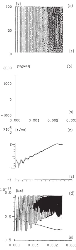
Fig. 5. A start-up by increasing the electrical power frequency linearly up to 20 kHz: (a) voltage supply; (b) angular position; (c) rotational speed; ( d) electric and drag torques.
acteristics of the electrodes. The matrix [C(0)] depends on the angular position of the rotor. Its components are functions of the angular position of the rotor and are computed by means of the static model presented in Section 2. For example, Fig. 4 shows the coefficient of capacitance of one phase of the stator versus the angular position of the rotor.
3.3. Calculation of the mechanical parameters
The parameters J, B, C1 and C2 are calculated an
alytically [5] or determined experimentally [2]. For the micromotor studied these parameters are equal to
J =2.8 X 10⁻²⁰ N m rad-1 s-2 C1 = 1.95 X 10-is N m B = 1.3 X 10⁻¹⁶ N m rad-1 s C2=2.96x10⁻¹¹Nm
v-
2 3.4. Simulation procedure (3)For a given voltage [V(t)], the status variables of the
system are the charge quantities [Q(t)], the angular
speed D(t) and the angular position 0(t). The simulation
procedure consists of determining first ail the parameters of the electromechanical model of the machine. Then, the resolution of the system (1) with a four-order Runge-Kutta method provides the dynamic response
of the motor corresponding to the given voltage [V(t)].
3.5. Erample of application
We have simulated a start-up corresponding to a constant acceleration of the machine until a permanent rotational speed of 200 000 rpm is reached (Fig. 5). The acceleration is obtained by applying a linear vari ation of the electrical frequency with respect to time. When the frequency increases, the speed oscillations decrease, and the operation is just the same as that of a synchronous machine. The maximal rotational speed, limited by the drag torques, was calculated to be about 220 000 rpm for the studied structure [5]. Many other types of operation, such as step positioning or quasi-dynamic operation can be studied, with different types of waveshapes of the supply voltages [8].
4. Conclusions
Two simulation proccdurcs for elcctromechanical de sign have been briefly dcscribed. These two procedures are bascd on a finite-element code. Finite-element analysis is a very powerful technique and is growing more and more flexible owing to the progress in data processing techniques. It can be implemented easily in a CAD integration for the design of micromotors. The examples treated show that this kind of tool allows us to design micromotors, to dcfinc the elcctronic supply strategies or simply to evaluatc bcttcr the fields of application of electric micromotors.
References
[1] J.H. Lang and S.F. Bart, Towarcl the design of succcssful clcctric micromotors, Proc. Solid-State St!11sors and Actuators Workshop, Hilton Head Island, SC, June 6-9, 1988, pp.127-130.
[2] S.F. Bart, M. Mehregany, L.S. Tavrow, J.H. Lang and S.D.
Scnturia, Elcctric micromotor dynamics, IEEE Trans. Electron. Devices, ED-39 (3) (March) 1992.
[3] E. Sarraute, Y. Lefèvre, B. Trannoy and M. Lajoie-Mazenc, Méthodes de calcul du champ électrostatique appliquées à la simulation de micromotcurs li capacités variables, Colloq11c sur
les Méthodes Infomiatiq11es de la Co11aptio11 hld11Stridlc, ESIM, Marseille, J1111e 18, 1993.
[4] N. Saclowski, Y. Lefèvre, M. Lajoie-Mazenc and J. Cros, Finite elcmcnt torque calculntion in clectrical machines while con sidering the movcment, IEEE Tram. Mag11., MAG-28 (1992) 1410-1413.
[5] E. Sarraute, Etude et modélisation de microactionncurs intégrés sur silicium, 171ès,: de Doctorat de l'JNPT, Toulouse, Octobcr 1993.
(6] L.S. Fan, Y.C. Tai and R.S. Muller, IC-proccssed clcctrostatic micromotors, Sen.sors a11d Actuators, 20 (1989) 41-47. [7] L.S. Fan, Y.C. Tai and R.S. Muller, IC-processed clectrostatic
synchronous micromotors, Sc11sors and Actuators, 20 (1989) 49-55.
[8) E. Sarraute, Y. Lefèvre and M. Lajoic-Mazcnc, Modclisation and simulation of the dynamic working of variables capacitances micromotors, ICEM '94, Paris, &pt. 5-,'3, 1994.