Three beneficiaries of project-oriented education in power electronics
Plumier Frédéric, Geuzaine Christophe
University of Liège, Dept. of Electrical Engineering and Computer Science,
ACE, Institut Montefiore B28,
B-4000 Liège, Belgium
Tel.: +32 / (0) – 43.66.37.35.
Fax: +32 / (0) – 43.66.29.10.
[email protected]; [email protected]
http://ace.montefiore.ulg.ac.be
Keywords
«Education methodology», «Teaching», «Industrial application», «Design», «Simulation».
Abstract
Power Electronics education at the University of Liège exhibits a particular feature, in that a person from industry is directly involved in the teaching of the introductory Power Electronics course since academic year 2007-2008. Together with him, we teach this subject making use of a project-oriented method. After two years of this experience, it is now of great interest to analyze the main benefits of this method for the students, the teaching team at the University and the company involved in the teaching process. In this paper we present through an example the method that is being used. We mention some interesting technical problems encountered by the students during their project work. We also present the evolution of the method from the first year of application in 2007-2008 to the forthcoming third year in 2009-2010.
I Introduction
“I can tell you how to get a Nobel prize”, said Paul Samuelson, Nobel prize in economy, “One condition is to have great teachers” [1]. Then we question ourselves: “how to be a great teacher in power electronics, with so many constraints: fast changing technology, limited time because of research projects to work on, limited number of persons in the research team, …?”. Though every particular case is different, the basic principles of a good education remain the same. Two characteristics seems to have the greatest importance in education: the teacher himself, and the teaching method [1]. In this paper, we focus on the project-oriented teaching method. This method has well known advantages compared to the classical teaching method. One major advantage concerns the development of the person with more soft skills as communication (written and oral), team-work, project organization and management [2]. Another advantage of the method is its realism. This means that giving a project to the students is giving them the question before the answer. In that way, we do not teach theory or knowledge for itself, but as an answer to a real problem. Trying to solve the real problem they are given, the students have to face the different aspects of power electronics such as choice of a topology, simulation of their circuit, realization and test of their prototype. During the project realization, the students encounter technical problems such as commutation transients, electromagnetic compatibility (EMC), control implementation,… This needs a constant supervision in order to help them reach their final goal. And this supervision takes a lot of time.
This paper presents the project-oriented approach together with a case study of a basic course on power converters and control in power electronics (30h theory + 30h practice) where someone from the industry is directly involved in the teaching process. This characteristic implies particular difficulties, but also several advantages for the students, the university research team, and the company involved in the course.
Some particular aspects of project-oriented teaching are detailed in the paper: Three basic conditions to succeed in project-oriented teaching,
How the implication of a person from the industry modifies the teaching method,
The interest to base a project-oriented education on your own research or development projects,
The triple-win consequence of this way of teaching.
II Project-oriented education in power electronics
Some universities have a global project-oriented education [3] while most are using the classical approach where a student goes through and passes many high-level courses supplemented with one or two small projects to obtain a Masters degree [2]. Our study concerns this second case. We will examine here three basic conditions to fulfill in order to succeed in project-oriented teaching in a sole course. We will then analyze the benefits of this method for the three actors of the teaching process.
a. Three basic conditions to succeed
There are at least three basic conditions to succeed in project-oriented teaching in a sole course. These conditions concern:
Choice of the project, Organization,
Supervision.
Choice of the project
The projects submitted to the students have to be authentic (to correspond to a realization they could meet in their future work) and challenging for them. The projects also have to be easy enough for them to complete in the allotted time. The projects would ideally interest the teaching team too. This could be the case if the projects are chosen to be parts of projects the research team is working on.
Organization
The description of the project has to be clear. The deadlines have to be clearly mentioned to the students. The methodology and the evaluation grid should also be described in order to clarify to the students what they have to do. This makes them more confident in their ability to solve the problem and makes them more motivated.
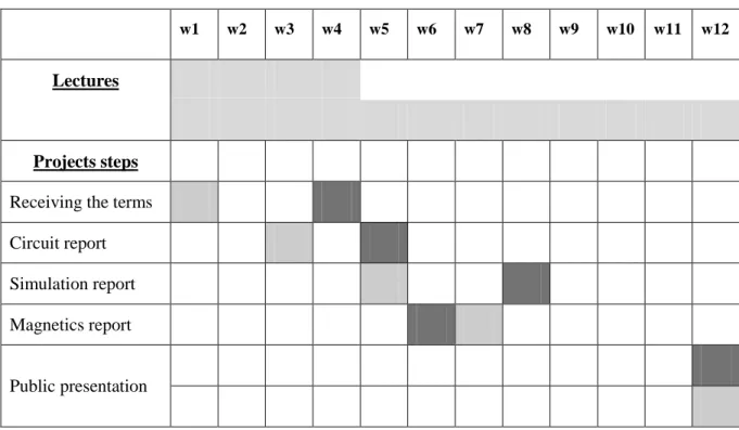
The way the lectures and the project work are integrated is of primary importance too. In year 2007-2008, we thought it was necessary to begin with theory only and then after some weeks to begin the projects. But it did not work as expected: the students were becoming quickly bored with the theory after two weeks and we had to make many efforts to get them motivated about the projects. This led to a profound change in the course schedule in 2008-2009, where the project work began from the first week (see Table I).
Supervision
As previously said, a real project implies real problems. The supervisors should ideally have a good experience in the field to be able to help the students solve the encountered problems. If not, they should work on the project in parallel with the students. This condition is quite easy to realize when the project you submit to the students is one of the projects you are working on.
The projects to supervise should not be too numerous to be able to maintain a high quality in supervision. That’s why the project-oriented method is preferably applied to a small number of students. In our case, 4 seems to be the maximum number of different projects we are able to supervise efficiently since there are only two supervisors (one technician and one engineer) who help the students for the projects. Each group is composed of 5 or 6 students. If we would have more students, we would be obliged to submit the same project to every group of students, which of course would be much more boring for them (and for us).
b. Three beneficiaries – Triple-win consequence of project-oriented education
Let us suppose that the project-oriented teaching is well structured and supervised and that the projects given to the students correspond to some of your own research projects. In that case what are the main benefits of this way of teaching?
Interest for the teachers
The questions of the students help you to further clarify your own understanding of the problem,
Some of the students can get motivated and choose a final project in your research team, Sometimes, you can see that many students would rather be working on their project than
doing anything else [4]. This way of teaching can then be particularly motivating for the teacher,
The time spent while teaching can be related to your own research activity if there is a possibility to choose some of the projects in your field of interest.
Interest for the students
First the basic project-oriented education advantages should be reminded: realism, soft skills as communication (written and oral), decision taking, development of friendship ability, team work and project management skills. The major advantage amongst these surely is the realism of the method that brings:
an integration of the different technical fields (power electronics, electromagnetism, microcontrollers, electronics, measurements, EMC, thermal management/cooling, control theory, modelling and simulation, reliability, … [2]) in one project,
a finalization of the knowledge (knowledge not studied for itself),
a better understanding of the difference between prototype, simulation, and theory, the motivation to realize yourself a real circuit.
When someone from the power electronics industry participates, the advantages of the method for the students are enhanced. The students learn another way of thinking: market share, competition, fabrication cost, Mean Time Between Failure (MTBF), that is to say it adds the technico-economical dimension that is very important for the students to take into account in their technical choices. The proposed projects are also more relevant.
Interest for the industry
There are different levels of implication for a person from the industry in project-oriented education. There seems to be two possibilities: either the person from the industry only helps to define the projects and participates to the final demonstration and presentation of the projects, or the person from the industry participates actively to the supervision of the projects. The latter case implies time-consuming meetings and supervision but creates a link between the students and the company. It eases the recruitment of the best students with a better up-to-date education. The close cooperation with university might also provides additional opportunities to get financed projects in collaboration with the academic world when there is a research project call.
III Project examples
In this section, we explain the choice and the content of the projects. We then mention some practical problems the students encounter on the way from theory to practice. We end up this section making an analysis of the evolution of the project-oriented method since the beginning in year 2007-2008.
a. Choice of the projects to submit to the students
In 2008-2009 we based the choice of the projects to submit to the students on one of our research projects (Fig. 1), called OptiSHER [5]. This choice makes the students benefit from our recent experience in the project while the research team gains a reduced work for supervision. The goal of
vgrid
Filter
~
PVarray
Full bridge inverter
C Boost Converter
VDC bus
Fig. 1: Optisher project [5]
this project is to realize a complete converter to drive a wind turbine, photovoltaic panels and batteries connected to a central DC link. An inverter gives to the system a connection to the grid. This project includes the design of at least three power converters. Out of the project of Fig.1, we submitted two projects to the students. One concerns the design and realization of the DC/DC Boost converter between the PV and the central DC capacitor link. Another concerns the design and realization of the bidirectional Buck-Boost to charge or discharge the battery with the DC capacitor link. As an example, the terms of the DC/DC Boost converter to the PV is given in Fig. 2.
Fig. 2: Terms of a “Boost converter” project in 2008-2009
Photovoltaic energy system Study and realization of a DC/DC converter
Solar energy is a green energy and can be used to produce electricity. But in order to integrate photovoltaic panels in a global system connected to the grid, it is often necessary to place a DC/DC converter between the panels and the intermediate DC voltage (Vdc bus) in order to match the voltage levels (see figure hereunder).
You are requested to design, simulate and realize the DC/DC converter for this application. Required performances are the following :
Uin min 250V
Uin max 350V
Uout 410V
Iout 5A
It is required to make a closed-loop control in order to regulate the output voltage.
The first tests will be realized with a reduced input voltage in order to guarantee the safety. If these first tests give good results, another series of tests will be conducted under the nominal input voltage, but under a reduced duty cycle (between 0% and 25%), in order to work under a reduced output voltage.
Battery Wind turbine Grid or Load Controller
b. Description of the work done during one project
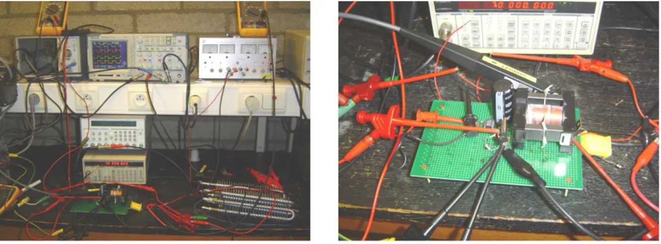
One project consists in designing a circuit, simulating and realizing a prototype. It includes the design of the magnetic components and their realization. It also includes the design of the PID compensator, but till now the students only implement a proportional compensator. The tests and measurements are an important part of the project work (Fig. 3).
Fig. 3: A flyback circuit under test (200W, 315V in – 0 to 315V out)
c. Practical problems encountered by the students
Realising a prototype of a DC/DC converter is not an easy task. But the students learn a lot through the practical problems they encounter. Here are examples of difficulties the students met during their project work.
Magnetic components
One problem is encountered during the design. In many cases, the calculated number of turns for a coil or a transformer is too large to be feasible. The students then have to find a solution. Either they will accept a greater current ripple, or they will have to enhance the switching frequency, or find if there was an error in their design. The same kind of problem often arise with the length of the gap.
Another problem encountered by students realizing a flyback transformer was to know the sense of the secondary coil in respect to the primary coil,
A third problem to mention concerns leakage flux in flyback transformer. The students making the flyback circuit of Fig. 3 first placed their coils next to each other. They had to change this and to place the coils one over the other in order to minimize the leakage flux. Of course, this was not so good for isolation. They made all the tests under a reduced voltage. When they tried to increase the voltage, their home-made isolation failed.
Fig. 4: Flyback transformers for a 200W, 315V in, 0-315V out converter. On the left, this first design did not work as expected because of an important leakage flux.
Miscellanous
One common encountered problem is when the students solder a diode or another component upside-down,
The students measure the losses in their converter by two ways: the simplest way is to make the difference between the input power and the output power. A second way that is interesting to have of more precise idea is to sum all the individual losses (commutation of each component, conduction losses, etc.) to get the total loss. Some of the students did not find the same amount of power loss, so the question for them is: where is the difference?
One group had a real problem with a 1200V Mos that seemed to let the current pass even when it was off. The only solution found was to use another component.
IV Evolution of the projects from 2007-2008 till 2009-2010
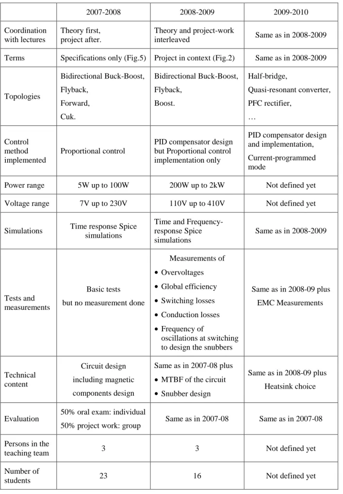
In order to give a global overview of the evolution of the project-oriented method, we listed in Table I the main characteristics of the projects proposed to the students from the first year of application in 2007-2008 till the forthcoming third year in 2009-2010. The main steps forward made in the first two years of application concern the teaching method, the technical content of the projects and the tests and measurements asked to the students. All details on the evolution of the projects between the first and the second year of application are given in Table II.
a. Teaching method
The first year of application of this method, we thought it was possible to begin the projects only after a couple of weeks of theory only, as shown in Table I. This solution was not efficient because after these weeks the students really were not so much interested about power electronics. That’s why in 2008-2009, we began the projects the first week. The students got motivated since the beginning and the project-oriented teaching worked really better.
Table I: Chronogram of Lectures and projects in 2007-08 (dark grey) and 2008-09 (soft
grey). The project steps are given in correspondence to the course week number.
w1 w2 w3 w4 w5 w6 w7 w8 w9 w10 w11 w12
Lectures
Projects steps
Receiving the terms Circuit report Simulation report Magnetics report
Public presentation
A second improvement in the teaching method concerns the way to present the terms of the project to the students. The first year, we only gave to the students the specification of the DC/DC converter (Fig. 5). The second year we improved this by adding the context (Fig. 2).
Fig. 5: Terms of a “Forward converter” project in 2007-2008
b. Technical content
Since the method was quite new for us too, the first year the technical content of the project was quite simple (Table II). The second year of application, the projects were based on higher power converters and we added snubber design, MTBF calculation, frequency simulation of the converters and PID compensator design. The fact that the power of the converters was increased so much implied many differences for the students. They have to think to a test sequence: they first test their circuit under a reduced voltage with an open-loop and closed-loop control. As a last test, the students increase the voltage to see if their converter is capable of working under its nominal voltage. It is interesting to note that the students were also a bit scared to work under a voltage of 400V DC. We had to explain to them the way to make their tests safely. This increased voltage added to the realism of the project-oriented method.
c. Tests and measurements
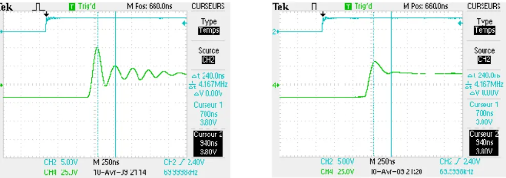
For the first year of application, the tests of the converters were not far from a “does it work or not?” test. In 2008-2009, we improved the method and asked the students to measure the efficiency of their converter and to find out where the main losses are located. Since the students have to design a snubber, they also measure the frequency of voltage oscillation during commutations (Fig. 6). In 2009-2010, we will also ask them to do a conducted emission measurement of their circuit. Of course we will not add supplementary measurements every year because we do not want to indefinitely increase the work for the students, but since we are still in the very beginning of the method we still have to improve many details.
Fig. 6: Diode voltage in a flyback converter without (left) or with snubber R 405Ω C 390pF (right).
DC/DC converter
Realize a converter according to the following specifications. You have to optimize the efficiency and make the price as cheap as possible. A comparison with the asymmetrical forward converter on the cost and efficiency criteria is required. A converter topology that could be used is given hereunder.
Specifications :
Power 80W
Max input voltage 57 V
Min input voltage 42 V
Output voltage 230 V
maximum voltage ripple ΔV 1 %
Table II: Evolution of the projects from 2007-2008 till 2009-2010 (prospective)
2007-2008 2008-2009 2009-2010 Coordination with lectures Theory first, project after.Theory and project-work
interleaved Same as in 2008-2009
Terms Specifications only (Fig.5) Project in context (Fig.2) Same as in 2008-2009
Topologies Bidirectional Buck-Boost, Flyback, Forward, Cuk. Bidirectional Buck-Boost, Flyback, Boost. Half-bridge, Quasi-resonant converter, PFC rectifier, … Control method implemented Proportional control
PID compensator design but Proportional control implementation only
PID compensator design and implementation, Current-programmed mode
Power range 5W up to 100W 200W up to 2kW Not defined yet
Voltage range 7V up to 230V 110V up to 410V Not defined yet
Simulations Time response Spice simulations
Time and Frequency-response Spice simulations Same as in 2008-2009 Tests and measurements Basic tests but no measurement done
Measurements of Overvoltages Global efficiency Switching losses Conduction losses Frequency of oscillations at switching to design the snubbers
Same as in 2008-09 plus EMC Measurements Technical content Circuit design including magnetic components design Same as in 2007-08 plus MTBF of the circuit Snubber design Same as in 2008-09 plus Heatsink choice
Evaluation 50% oral exam: individual
50% project work: group Same as in 2007-08 Same as in 2007-08 Persons in the
teaching team 3 3 Not defined yet
Number of
V Conclusions
In this paper we described our experience of project-oriented education in the introductory power electronics course at the University of Liège. We showed that three basic conditions have to be fulfilled in order to succeed in this way of teaching: a good choice of the projects to submit to the students, a good organization of the course and a good supervision of the projects. We mentioned the particular case where someone from the industry is involved in the teaching process and detailed the benefits for the students, for the teaching team at the University and for the company.
The main advantage of the project-oriented education method for the students comes from the fact that you introduce to them power electronics in the right order. The students are first given a problem to solve and in order to bring a solution to this problem, they need to use power electronics: choice of a circuit topology, simulation of the circuit, realization and test of a prototype,... Along the way, the students encounter many practical problems: driving the switches, overvoltages and currents at switching, EMC,... before they were told about the existence of these problems. Through the process of finding the cause and the solution to these problems, the students gain a real integration of the different fields of power electronics into one project: devices, topologies, control, measurements, magnetic components, etc.
When someone from the industry is involved, the students work on up-to-date problems and it makes this approach even more motivating for them. The teaching team at the University and the company gain the benefit either to try to realize a converter they never did, or instead to make the students work on projects they are themselves working on. Through the teaching process, the company gain a close collaboration with the University which eases the way to get financed projects together. It also gives the opportunity to the company to recruit the best students with a better up-to-date and design-oriented education in power electronics.
References
[1] Viau R.: La motivation des étudiants à l’Université: mieux comprendre pour mieux agir, Conference 2006, University of Liège, Belgium.
[2] Blaabjerg F., Chen Z., Teodorescu R.: Renewable energy systems in the power electronics curriculum, power electronics education 2005, IEEE workshop, pp 58-68.
[3] Web-page for study information in Aalborg University Denmark, www.iet.aau.dk.
[4] Viau R.: A model to explain the motivational dynamics of eminent scientists, 10th international conference on motivation 2006, University of Koblenz-Landau, Germany.
[5] DGTRE: Optisher FuturEnergy project, Jambes Belgium.
[6] Erickson R.W., Maksimović D.: Fundamentals of power electronics, second edition, Springer science+business media, ISBN 0-7923-7270-0.
![Fig. 1: Optisher project [5]](https://thumb-eu.123doks.com/thumbv2/123doknet/5890265.144004/4.892.265.592.113.363/fig-optisher-project.webp)