Title :
Anisotropic behaviour in the magnetic field dependence of the low temperature electrical resistance of calcium-doped lanthanum manganate thin films grown by RF magnetron sputtering.
Authors :
B. Vertruyen1*, L. Dusoulier1, J.-F. Fagnard2, Ph. Vanderbemden2, G. Vanhoyland3, M. Ausloos4, J. Delwiche1, A. Rulmont1, R. Cloots1
1 SUPRATECS, Chemistry Institute B6, University of Liège, B-4000 Liège, Belgium
2 SUPRATECS, Department of Electrical Engineering and Computer Science B28, University of Liège, B-4000 Liège, Belgium
3 Laboratory of Inorganic and Physical Chemistry, IMO, Limburgs Universitair Centrum, B-3590 Diepenbeek, Belgium
4 SUPRATECS, Physics Institute B5, University of Liège, B-4000 Liège, Belgium * corresponding author :
e-mail : [email protected], phone : + 32 4 3663452, fax : + 32 4 3663413
Abstract
We report about the magnetoresistive properties of calcium-doped lanthanum manganate (LCMO) thin films grown by RF magnetron sputtering on single crystalline LaAlO3 and MgO substrates. Two orientations of the magnetic field with respect to the electrical current have been studied : (i) magnetic field in the plane of the film and parallel to the electrical current, (ii) magnetic field perpendicular to the plane of the film. The film grown on LaAlO3 is characterised by an unusual magnetoresistive behaviour when the magnetic field is applied perpendicular to the film plane : the appearance of two bumps in the field dependence of the resistance is shown to be related to the occurrence of anisotropic magnetoresistive effects in manganate films.
PACS numbers : 75.50.-y ; 75.70.-i ; 75.30.Gw
Keywords : manganates, perovskite, colossal magnetoresistance, anisotropic magnetoresistance
1.Introduction
Since the early nineties, there has been a renewed interest for the mixed-valence manganates Ln1-xAxMnO3 (where Ln is a lanthanide cation and A is often an alkaline earth ion), due to the discovery of their colossal magnetoresistance (CMR) [1-4]. Thin films of these materials are especially studied for their potential technological applications, e.g. as magnetic sensors or in computer memory systems [5,6]. A comprehensive review of the literature concerning manganate thin films can be found in reference [7].
For practical applications, the most important property of CMR thin films is the low field magnetoresistance effect, which is typically much larger in polycrystalline films than in single crystalline epitaxial films [8-11]. However, the study of epitaxial films is essential for the understanding of the underlying physical mechanisms. More specifically, a comparison of polycrystalline and single crystalline thin films can give valuable information about grain-boundary-related effects [12,13], stress-induced anisotropy [14], magnetocrystalline anisotropy [15] or demagnetisation effects [16,17].
In this paper, we report about the low field magnetoresistance properties of calcium-doped lanthanum manganate (LCMO) thin films grown by magnetron sputtering on single crystalline LaAlO3 and MgO substrates. Due to the different lattice parameters of the two substrates, we have obtained a (100)-oriented film on LaAlO3 and a polycrystalline film on MgO. In both cases, the magnetoresistance properties have been studied as a function of the magnetic field orientation with respect to the electrical current. Most of the previous studies [17,12,14,18-20] were restricted to in-plane field orientation, with the magnetic field either parallel or perpendicular to the electrical current. However, it turns out that unusual features occur when the magnetic field is perpendicular to the film plane [16,21].
The latter geometry was studied in the pioneering work of Eckstein et al. [16] on tensile-strained LCMO epitaxial films. The objective of the present study was to find out whether a similar analysis could be applied in the case of stress-released LCMO films. Our results concerning the polycrystalline film grown on MgO were found to be helpful in identifying the specific features of the oriented film.
Section 2 gives the details of the experimental procedure. Section 3 is divided in two parts. The first one deals with the characterisation of the films : crystallographic structure, microstructure and basic electrical and magnetoresistive properties. The second part of Section 3 is devoted to the discussion of the magnetoresistive properties as a function of the
2. Film preparation and experimental details
The La0.7Ca0.3MnO3 target was prepared from a powder obtained by the "Deposition by Aqueous Acetate Solution" (DAAS) method [22]. Stoichiometric amounts of acetates of lanthanum, calcium and manganese were dissolved in an acetic acid solution. Evaporation of the solution at 110°C yielded a glassy gel, which was pyrolysed at 600°C for 6 hours with a slow heating rate (75°/h). The precursor powder was subsequently annealed at 1200°C for 48 hours, uniaxially pressed into a 30-mm diameter target and finally sintered at 1350°C for 48 hours. The purity and chemical composition of the target were checked by X-ray diffraction and energy dispersive X-ray analysis.
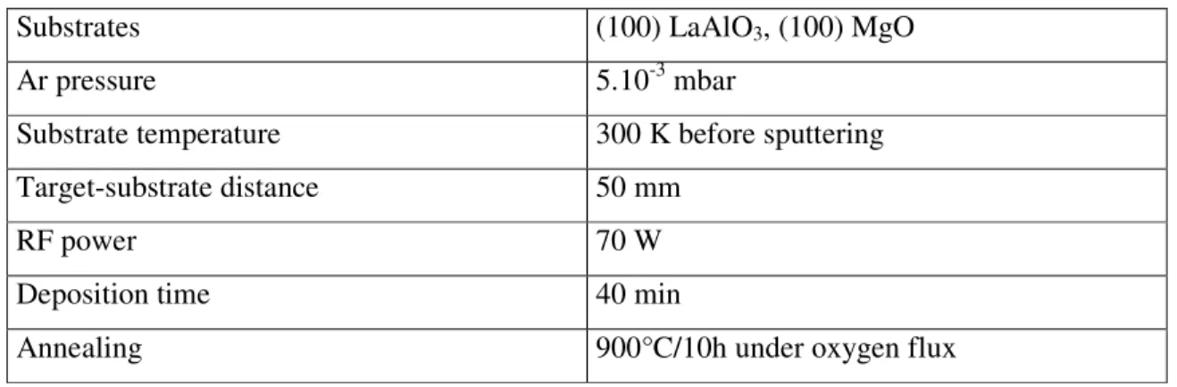
Films were grown by RF magnetron sputtering on two different substrates : single crystalline (100) LaAlO3 and single crystalline (100) MgO, whose (pseudo)-cubic cell
parameters are respectively 3.79 Å and 4.21 Å. The details of the film growth are summarised in Table 1. After deposition the films were annealed ex-situ under flowing oxygen at 900°C during 10 h.
X-ray diffraction was carried out with a Siemens D5000 diffractometer equipped with Gobel mirror (Cu K radiation). Electrical resistance and magnetic moment were measured as a function of temperature and magnetic field, respectively by the standard four-probe
technique in a PPMS system (Quantum Design) and in a Vibrating Sample Magnetometer VT9 (Oxford Instruments). Atomic force microscopy (AFM) was performed in a D3100 Digital Instrument Nanoscope.
3. Results and discussion Film characterisation
X-ray diffraction confirmed that the as-deposited films were amorphous, as expected from the low temperature of the substrates during the growth (300 K before sputtering). Subsequent oxygen annealing was performed in order to obtain the crystalline perovskite phase. In the case of the film grown on LaAlO3, only (h00) pseudo-cubic reflections were observed in the X-ray diffraction pattern. The cell parameters of this film correspond to those
of bulk La0.7Ca0.3MnO3 material (apseudo-cubic = 3.87 Å [7]) : ex-situ crystallisation leads to a strain-released (100)-oriented crystallographic structure. On the contrary, the film grown on (100) MgO was only partially oriented, since also the (110) reflection was observed. Indeed, the film-substrate crystallographic mismatch {(as-ab)/as, where as and ab are the pseudo-cubic lattice parameter of the substrate and of the bulk manganate respectively} is much larger in the case of the MgO substrate (+9 %) than in the case of the LaAlO3 substrate (-2.4 %).
AFM experiments indicate that both films have a thickness of about 500 nm and that the roughness of the film surface is larger for the film grown on MgO (mean roughness Rms = 30 nm) than for the film grown on LaAlO3 (Rms = 5 nm).
Both films display a resistive transition from an insulating state at high temperature to a metallic-like state at low temperature. The transition temperature of the film grown on
LaAlO3 (275 K) is consistent with literature data for the La0.7Ca0.3MnO3 composition [19]. On the contrary, the broad resistive transition of the film grown on MgO occurs at a significantly lower temperature (225 K). The low temperature resistivity of the film grown on LaAlO3 (about 5.10-4Ω cm) lies well within the range observed for La
0.7Ca0.3MnO3 single crystals [23] and epitaxial thin films [8,24,25], whereas the low temperature resistivity of the film grown on MgO is two orders of magnitude larger. This suggests that the contribution of possible small-angle grain boundaries [26] or microstructural defects [24] to the overall electrical resistance of the film grown on LaAlO3 remains limited.
Figure 1 shows the magnetoresistance vs. temperature curves for both films for magnetic fields µ0H = 0.5, 1, 2 and 5 T. In the case of the film grown on the LaAlO3 substrate, the magnetoresistance displays a sharp peak around the resistive transition temperature and is very small at low temperature. On the contrary, the film grown on MgO displays a significant magnetoresistance in a much wider temperature range, i.e. from the transition temperature down to 20 K. Comparison with literature data [8,18,23] indicates that the properties of the (100)-oriented film grown on LaAlO3 are similar to those ofbulk single crystals and epitaxial thin films, while the behaviour of the film grown on MgO is typical of polycrystalline films and bulk compounds.
Low field magnetoresistance effect (LFMR)
In the present section, the magnetoresistance properties of the films are studied for two orientations of the magnetic field with respect to the electrical current : (i) magnetic field
parallel to the plane of the film and parallel to the electrical current, and (ii) magnetic field perpendicular to the plane of the film.
Figure 2 shows the magnetic field dependence of the electrical resistance at 20 K for the films grown on LaAlO3 and MgO when the magnetic field is applied parallel to the plane of the film and parallel to the electrical current. Data corresponding to µ0H ranging between -0.5 and 0.5 T are shown in the main figure ; more detailed measurements between -0.05 and 0.05 T are displayed in the insets. For the sake of clarity, the data corresponding to the first magnetisation have been omitted. In order to make the comparison between the two films easier, the resistance measurements are presented as R/R(0) values, where R(0) is the resistance in the hysteresis loop at H=0.
The data displayed in Fig. 2 show that both films have qualitatively the same behaviour but that the orders of magnitude of the magnetoresistive effects are very different. This can be attributed to the polycrystalline nature of the film grown on MgO : the fact that grain
boundaries lead to a low-field magnetoresistive effect is experimentally well established [23,27-30], although the fundamental mechanism of this effect is still a matter of debate [12,13,31,32].
Both films display a very similar hysteretic behaviour at low field (see insets of Fig. 2). Starting from the low-resistance state at positive magnetic field, the resistance increases when the magnetic field decreases and reaches a maximum value for a slightly negative field rather than at 0 T. When the field is scanned from negative to positive values, a similar dependence is observed, with a resistance peak occurring for a slightly positive magnetic field. The origin of this behaviour, also observed by other authors [18,19,33], is illustrated in figure 3 in the case of the film grown on LaAlO3 : the magnetic field corresponding to the maximum resistance value is roughly equal to the coercive field of the film. At the coercive field, the macroscopic magnetisation is equal to zero : this corresponds to a maximum of the magnetic disorder in the film and therefore to a maximum of the electrical resistance [34,35]. In conclusion, the hysteresis in the R(H) curve is due to the existence of magnetic hysteresis.
Incidentally, it can be seen in figure 4a (which displays the complete m(H) curve for H//film configuration) that the magnetic hysteresis of the film grown on LaAlO3 remains significant well above the coercive field. The magnetic hysteresis disappears only whenthe magnetic saturation is nearly complete. A possible explanation for this phenomenon may be found in the unusually large thickness of the film (500 nm). For such large thickness, it is likely that the film contains some domain walls parallel to the film plane. The confinement of
these parallel domain walls within the 500nm-thick layer might lead to an additional irreversibility of the domain wall motion, resulting in an increased magnetic hysteresis.
In the last part of this paper the results obtained for H//film configuration are compared to measurements carried out with H⊥film configuration. Figure 5 shows the magnetic field
dependence of the electrical resistance at 20 K for the films grown on LaAlO3 and MgO when the magnetic field is applied perpendicular to the plane of the film.
The resistance drop caused by the magnetic field is again much higher in the case of the polycrystalline film grown on MgO than for the film grown on LaAlO3. However, these effects are obtained for much larger magnetic fields than in the H//film configuration. For example, in the case of the film grown on LaAlO3, a 0.25% magnetoresistance requires 2 T for H⊥film, instead of 0.5 T for H//film. This is expected from the demagnetisation effects
[17] : due to the two-dimensional geometry of the film, the demagnetisation effect tends to zero in the plane of the film but is much higher in the perpendicular direction. In other words, a much higher applied field is required to obtain a given internal field when the magnetic field is applied perpendicular to the film plane.
Figure 5 also shows that both films display the low field hysteretic behaviour already observed for the H//film configuration. However, in the case of the film grown on LaAlO3, the H⊥film magnetic moment data displayed in figure 4b show that there is no
correspondence between this resistive feature and the magnetic properties : the magnetic hysteresis is very small and disappears at about 0.1 T, while the “hysteretic maxima” of the resistive curve are observed at 0.2 T. Actually, the most likely origin of this hysteretic feature is a small misorientation of the magnetic field with respect to the direction perpendicular to the film, resulting in a non-zero magnetic field component in the film plane. From the field values corresponding to the resistive peaks, the misorientation can be estimated to be about 3°.
Having dealt with this issue, we turn to the main difference observed between the H//film and H⊥film magnetoresistance properties of the film grown on LaAlO3 : the H⊥film magnetoresistance curve (Fig. 5) displays two additional peaks. Scanning the magnetic field from positive to negative values produce these resistance peaks at both positive and negative fields.
In order to find out the origin of this orientation-dependent phenomenon, it is necessary to analyse the influence of the perpendicular magnetic field orientation on the magnetisation
process. For H⊥film configuration, the saturation corresponds to a state where the magnetic
moment is perpendicular to the current direction. However, a comparison of the magnetic moment curves for H//film and H⊥film configurations (see Fig. 4) shows that the magnetic
easy axis at H=0 is not directed perpendicularly to the plane, although an out-of-plane easy axis might have been expected from the theoretical compressive strain due to the film-substrate lattice mismatch [33,36,37]. Actually, X-ray diffraction results have shown that the crystallographic structure is stress-released due to the thermal annealing : the
magnetocrystalline anisotropy being drastically suppressed, the demagnetisation effects lead to in-plane orientation of the magnetic moment. In summary, when the magnetic field is applied perpendicular to the film plane, the magnetisation process corresponds to a
progressive rotation of the magnetic moment with respect to the electrical current direction. By comparison of figures 4b and 5, it can be seen that the resistance bump occurs at a magnetic field Hb close to the field H* where the magnetisation increase becomes very small (The small difference between Hb and H* will be addressed later in the discussion). This seems to indicate that the electrical resistivity depends on the angle between magnetisation and electrical current. Such an anisotropic magnetoresistance effect (AMR) is well-known in metallic ferromagnets, where the dependence of the resistance on the current/magnetisation angle is ascribed to spin-dependent scattering of the conduction electrons [19].
Using these AMR ideas and temporarily neglecting the low-field hysteretic feature resulting from the misorientation of the magnetic field, it is possible to explain the magnetoresistive behaviour of the LCMO film grown on LaAlO3 as follows : (i) When a magnetic field is applied perpendicular to the film plane, the magnetisation (initially directed in the plane) tends to rotate in order to become perpendicular to the film plane. Upon
increasing the magnetic field, the current/magnetisation angle increases and therefore the electrical resistance increases, due to an AMR effect. During this process the demagnetisation field cancels the applied field and the internal field is zero. (ii) When the applied field
becomes equal to the demagnetisation field, the magnetisation has become perpendicular to the film plane. On increasing the magnetic field further, the internal field is no longer zero and improves the ferromagnetic alignment of the Mn spins, which leads to a decrease of the electrical resistance, as predicted by the double exchange model [34,35].
The magnetoresistive behaviour observed in figure 5 is actually more complicated, due to the superimposition of the hysteretic feature induced by an in-plane component of the magnetic field. This artefact is noticeable in the experimental curve because at 0.2 T (= field at which the hysteretic maximum occurs), the angle between the magnetisation vector and the
electrical current is only 18° (as calculated from the value at 0.2 T of the perpendicular-to-film component of the magnetic moment) : the AMR effect is still weak enough for the marginal in-plane effect to be seen.
In the literature, a similar behaviour with two peaks in the resistance vs. field curve for perpendicular field orientation was observed by Eckstein et al. [16] in tensile-stressed LCMO films grown on SrTiO3 substrates. They observed that the resistance of their films increases when the angle between the magnetic field and the electrical current increases. Moreover they could satisfactorily reproduce some of their results by a phenomenological equation that was initially developed for describing the AMR effect in metallic ferromagnets [16]. From a theoretical point of view, it is also worth pointing out that Ziese et al. [19] have shown that a small AMR effect can be predicted in the case of manganate compounds by a simplified model where the spin-orbit coupling is included as a perturbation in the Hamiltonian.
It must be stressed that the AMR mechanism does not take place if the initial
magnetisation is perpendicular to the plane, i.e. if the magnetocrystalline anisotropy favours perpendicular-to-plane magnetisation and is large enough to overcome the demagnetisation field so that the magnetic easy axis is perpendicular to the plane. Indeed the Pr0.67Sr0.33MnO3 thin films with out-of-plane easy axis grown by Wang et al. [33] on LaAlO3 do not display an AMR behaviour.
The LCMO films of Eckstein et al. [16] were grown on SrTiO3 substrates, whose lattice parameter is larger than that of bulk LCMO : these films are in tension in the plane of the substrate and display a stress-induced magnetocrystalline anisotropy which favours in-plane magnetisation, as confirmed by their measurements of the magnetisation as a function of the amplitude and direction of the magnetic field. However, it is interesting to note that the results of the present study prove that AMR effect can be observed even when no stress-induced magnetocrystalline anisotropy is present : in this case the in-plane easy axis is imposed by the demagnetisation effects. Actually, if both magnetocrystalline and shape anisotropies are present, the field value necessary to reach a perpendicular magnetisation is determined by the combination of both anisotropies.
However, as mentioned above, there is no perfect correspondence between the field where the resistivity maximum is observed (Hb ~ 0.75 T) and the H* field (~ 0.9 T) where the magnetisation increase becomes very small. This is probably related to the existence of magnetic domains in the films. Up to now, the AMR effect was discussed considering a
analysed in terms of magnetic domains : during the rotation of the magnetisation in the different domains, the angles between the magnetisation vectors of adjacent domains are modified. This process is likely to improve the overall alignment of the Mn spins, leading to a decrease of the resistivity as predictedby the double exchange mechanism [34,35]. On the whole, the combination of the two effects might explain that the resistivity maximum takes place at a magnetic field smaller than H*.
Another point to be discussed is the fact that no AMR effect was observed in the case of the polycrystalline film grown on MgO (see figure 5). Indeed, the films grown on LaAlO3 and on MgO have very different orders of magnitude of magnetoresistance : in the case of the film grown on MgO, the magnetoresistance associated to the grain boundaries is so large that any contribution of the much smaller anisotropic magnetoresistance would be negligible.
Similarly, any influence of the large roughness of this film on the AMR properties [38] would be masked by the grain-boundary-related magnetoresistance. Instead of the peak in the magnetoresistance curve, there is a modification of the slope in the R(H) curve, which represents the limit between the so-called low-field and high-field magnetoresistive behaviours typical of polycrystalline samples [30,39,40].
All the results discussed in this paper deal with configurations where the current flows in the plane of the film. It would be interesting to investigate what happens when the current direction is perpendicular to the film plane, especially because the so-called CPP geometry is very common in manganite-based spin-tunneling heterostructures [6,9,41,42]. However, to the best of our knowledge, this case has not been extensively studied in the literature. Such measurements are technically difficult in the case of a single manganite layer and would require complex film patterns for which demagnetization effects could be difficult to evaluate. In one of the very few reports concerning the CPP geometry for manganite-only structures, Klein et al. [43] have observed an unusual insulating R(T) behaviour in tensile-strained LCMO when the current is perpendicular to the film plane.
4. Conclusions
We have reported about the magnetoresistance properties of calcium-doped lanthanum manganate (LCMO) thin films grown by magnetron sputtering on single crystalline LaAlO3 and MgO substrates. Two orientations of the magnetic field with respect to the electrical
current have been examined : (i) magnetic field in the plane of the film and parallel to the electrical current, (ii) magnetic field perpendicular to the plane of the film.
Due to the large mismatch between the lattice parameters of MgO and LCMO, the film grown on MgO is polycrystalline and displays a significant grain-boundary-related low field magnetoresistance, whatever the field orientation.
When the magnetic field is applied parallel to the film plane, a hysteretic behaviour is observed for films grown on both substrates. This phenomenon is related to the existence of a magnetic hysteresis : maxima in the resistance vs. field curves are observed at the coercive field.
The magnetoresistive properties of the film grown on LaAlO3 are characterised by a special feature when the magnetic field is applied perpendicular to the film plane : the appearance of two bumps in the field dependence of the resistance. These results have been discussed with reference to the occurrence of an anisotropic magnetoresistive effect in manganate films with in-plane magnetisation easy axis.The magnetoresistive phenomena were shown to result from the combination of the AMR mechanism with the domain magnetisation process.
Ackowledgements
B.V. thanks the F.N.R.S. (Belgium) for a Scientific Research Worker grant. G.V. is a Post-Doctoral Fellow of the Fund for Scientific Research – Flanders (Belgium) (F.W.O.). J.D. acknowledges the F.N.R.S. (Belgium) and the 'Patrimoine de l'Université de Liège' for financial support.
References
[1] K. Chahara, T. Ohno, M. Kasai and Y. Kozono, Appl. Phys. Lett. 63 (1993) 1990. [2] R. von Helmolt, J. Wecker, B. Holzapfel, L. Schultz and K. Samwer, Phys. Rev. Lett. 71 (1993) 2331.
[3] J.M.D. Coey, M. Viret and S. von Molnar, Adv. Phys. 48 (1999) 167.
[4] B. Raveau, A. Maignan, C. Martin and M. Hervieu, Chem. Mater. 10 (1999) 2641.
[5] T. Venkatesan, M. Rajeswari, Z.W. Dong, S.B. Ogale and R. Ramesh, Phil. Trans. R. Soc. Lond. A 356 (1998) 1661.
[6] P.P. Freitas, in : M. Ziese and M.J. Thornton (Eds), Spin Electronics, Springer, Berlin, 2001, pp. 464-485.
[7] W. Prellier, P. Lecoeur and B. Mercey, J. Phys. : Condens. Matter 13 (2001) R915. [8] G.J. Snyder, R. Hiskes, S. DiCarolis, M.R. Beasley and T.H. Geballe, Phys. Rev. B 53 (1996) 14434.
[10] A. Gupta, G.Q. Gong, G. Xiao, P.R. Duncombe, P. Lecoeur, P. Trouilloud, Y.Y. Wang, V.P. Dravid and J.Z. Sun, Phys. Rev. B 54 (1996) R15629.
[11] K. Steenbeck, T. Eick, K. Kirsch, K. O'Donnel and E. Steinbeiss, Appl. Phys. Lett. 71 (1997) 968.
[12] J.E. Evetts, M.G. Blamire, N.D. Mathur, S.P. Isaac, B.S. Teo, L.F. Cohen and J.L. MacManus-Driscoll, Phil. Trans. R. Soc. Lond. A 356 (1998) 1593.
[13] R.Gross, L. Alff, B. Büchner, B.H. Freitag, C. Höfener, J. Klein, Y. Lu, W. Mader, J.B. Philipp, M.S.R. Rao, P. Reutler, S. Ritter, S. Thienhaus, S. Uhlenbruck and B. Wiedenhorst, J. Magn. Magn. Mater 211 (2000) 150.
[14] J. O'Donnell, M. Onellion, M.S. Rzchowski, J.N. Eckstein and I. Bozovic, Phys. Rev. B 55 (2001) 5873.
[15] N.D. Mathur, M.H. Jo, J.E. Evetts, M.G. Blamire, J. Appl. Phys. 89 (2001) 3388. [16] J.N. Eckstein, I. Bozovic, J. O'Donnell, M. Onellion and M.S. Rzchowski, Appl. Phys. Lett. 69 (1996) 1312.
[17] S. Valencia, O. Castano, J. Fontcuberta, B. Martinez and L. Balcells, J. Appl. Phys. 94 (2003) 2524.
[18] X.W. Li, A. Gupta, G. Xiao, G.Q. Gong, Appl. Phys. Lett. 71 (1997) 1124. [19] M. Ziese and S.P. Sena, J. Phys. : Condens. Matter 10 (1998) 2727.
[20] M. Bibes, O. Gorbenko, B. Martinez, A. Kaul and J. Fontcuberta, J. Magn. Magn. Mater. 211 (2000) 47.
[21] H.S. Wang, E. Wertz, Y.F. Hu and Q. Li, J. Appl. Phys. 87 (2000) 6749.
[22] S. Yang, C.T. Lin, K. Rogacki, B. Dabrowski, P.M. Adams and D.M. Speckman, Chem. Mater. 10 (1998) 1374.
[23] C.S. Hong, W.S. Kim, E.O. Chi, K.W. Lee and N.H. Hur, Chem. Mater. 12 (2000) 3509. [24] K.A.Thomas, P.S.I.P.N. de Silva, L.F.Cohen, A.K.M. Akther Hossain, M. Rajeswari, T. Venkatesan, R. Hiskes and J.L. MacManus-Driscoll, J. Appl. Phys. 84 (1998) 3939.
[25] M. Paranjape, A.K. Raychaudhuri, N.D. Mathur and M.G. Blamire, Phys. Rev. B 67 (2003) 214415.
[26] S.P. Isaac, N.D. Mathur, J.E. Evetts and M.G. Blamire, Appl. Phys. Lett. 72 (1998) 2038. [27] A.K.M. Akther Hossain, L.F. Cohen, F. Damay, A. Berenov, J. MacManus-Driscoll, N.M. Alford, N.D. Mathur, M.G. Blamire and J.E. Evetts, J. Magn. Magn. Mater. 192 (1999) 263.
[28] L. Balcells, B. Martinez, F. Sandiumenge and J. Fontcuberta, J. Magn. Magn. Mater. 211 (2000) 193.
[29] N.D.Mathur, G. Burnell, S.P. Isaac, T.J. Jackson, B.S. Teo, J.L. MacManus-Driscoll, L.F. Cohen, J.E. Evetts and M.G. Blamire, Nature 387 (1997) 266.
[30] B. Vertruyen, R. Cloots, A. Rulmont, G. Dhalenne, M. Ausloos and Ph. Vanderbemden, J. Appl. Phys. 90 (2001) 5692.
[31] A. Gupta and J.Z. Sun, J. Magn. Magn. Mater. 200 (1999) 24. [32] N. Zhang, W. Ding and W. Zhong, Phys. Lett. A 253 (1999) 113.
[33] H.S. Wang, Q. Li, K. Liu and C.L. Chien, Appl. Phys. Lett. 74 (1999) 2212. [34] C. Zener, Phys. Rev. 82 (1951) 403.
[35] C.N.R. Rao, A.K. Cheetham and R. Manesh, Chem. Mater. 8 (1996) 2421.
[36] W. Prellier, M. Rajeswari, T. Venkatesan and R.L. Greene, Appl. Phys. Lett. 75 (1999) 1446.
[37] Z.H.Wang, G. Cristiani, H.U. Habermeier, Z.R. Zhang and B.S. Han, J. Appl. Phys. 94 (2003) 5417.
[38] Y.P. Zhao, R.M. Gamache, G.C. Wang, T.M. Lu, G. Palansantzas and J.T.M. De Hosson, J. Appl. Phys. 89 (2001) 1325.
[39] L. Balcells, J. Fontcuberta, B. Martinez and X. Obradors, Phys. Rev. B 58 (1998) R14697.
[40] J. Rivas, L.E. Hueso, A. Fondado, F. Rivadulla and M.A. Lopez-Quintela, J. Magn. Magn. Mater. 211 (2000) 57.
[41] E. Favre-Nicolin, L. Ranno, C. Dubourdieu and M. Rosina, Thin Solid Films 400 (2001) 165.
[42] Y. Luo, A. Kaufler and K. Samwer, Appl. Phys. Lett. 77 (2000) 1508.
[43] J. Klein, J. B. Philipp, G. Carbone, A. Vigliante, L. Alff and R. Gross, Phys. Rev. B 66 (2002) 052414.
Figure captions
Fig.1 : Temperature dependence of the magnetoresistance ratio (R0-RH)/R0, where R0 and RH are respectively the electrical resistance without and with magnetic field, for magnetic fields µ0H between 0.5 T and 5T. Main figure : data for the film grown on LaAlO3. Inset : data for the film grown on MgO.
Fig.2 : Magnetic field dependence of the electrical resistance at 20 K for the films grown on LaAlO3 (black circles) and MgO (white triangles), when the magnetic field is applied in the plane of the film, parallel to the electrical current. Zooms of the low-field regions are given in insets. Notice the different resistance scales.
Fig.3 : LCMO film grown on LaAlO3 : magnetic field dependence at 20 K of the resistance (black circles) and magnetic moment (white triangles) for H//film configuration.
Fig.4 : Magnetic field dependence of the magnetic moment at 20 K for the film grown on LaAlO3 when the magnetic field is applied (a) in the film plane or (b) perpendicular to the film plane. Notice the different resistance scales. H* is the field where the magnetisation increase becomes very small for H⊥film configuration.
Fig.5 : Magnetic field dependence of the electrical resistance at 20 K for the films grown on LaAlO3 (black circles) and MgO (white triangles) for H⊥film configuration. Notice the different resistance scales. Hb is the field which corresponds to the resistance bump for the film grown on LaAlO3.
Table 1: Experimental conditions for RF magnetron sputtering of the La0.7Ca0.3MnO3 films
Substrates (100) LaAlO3, (100) MgO
Ar pressure 5.10-3 mbar
Substrate temperature 300 K before sputtering
Target-substrate distance 50 mm
RF power 70 W
Deposition time 40 min