HAL Id: hal-01073624
https://hal.archives-ouvertes.fr/hal-01073624
Submitted on 10 Oct 2014
HAL is a multi-disciplinary open access
archive for the deposit and dissemination of
sci-entific research documents, whether they are
pub-lished or not. The documents may come from
teaching and research institutions in France or
abroad, or from public or private research centers.
L’archive ouverte pluridisciplinaire HAL, est
destinée au dépôt et à la diffusion de documents
scientifiques de niveau recherche, publiés ou non,
émanant des établissements d’enseignement et de
recherche français ou étrangers, des laboratoires
publics ou privés.
Low speed doubly salient permanent magnet generator
with passive rotor for a tidal current turbine
Nacereddine Harkati, Luc Moreau, El Hadi Zaim, Jean-Frederic Charpentier
To cite this version:
Nacereddine Harkati, Luc Moreau, El Hadi Zaim, Jean-Frederic Charpentier. Low speed doubly salient
permanent magnet generator with passive rotor for a tidal current turbine. International Conference
on Renewable Energy Research and Applications (ICRERA), 2013, Oct 2013, Spain. pp.528 - 533,
�10.1109/ICRERA.2013.6749811�. �hal-01073624�
Science Arts & Métiers (SAM)
is an open access repository that collects the work of Arts et Métiers ParisTech
researchers and makes it freely available over the web where possible.
This is an author-deposited version published in: http://sam.ensam.eu
Handle ID: .http://hdl.handle.net/10985/8715
To cite this version :
Nacereddine HARKATI, Luc MOREAU, El Hadi ZAIM, Jean-Frederic CHARPENTIER - Low speed doubly salient permanent magnet generator with passive rotor for a tidal current turbine -In: International Conference on Renewable Energy Research and Applications (ICRERA), 2013, Spain, 2013-10 - Renewable Energy Research and Applications (ICRERA), 2013 International Conference on - 2013
Any correspondence concerning this service should be sent to the repository Administrator : archiveouverte@ensam.eu
Low speed doubly salient permanent magnet
generator with passive rotor for a tidal current turbine
Determination of inductances under saturated conditions
N. Harkati , L. Moreau , M.E. Zaïm
IREENA
Saint-Nazaire, France e-mail: nacereddine.harkati@univ-nantes.frJ.F. Charpentier
IRENav
Brest, France e-mail: jean-frederic.charpentier@ecole-navale.frAbstract— This paper presents a low speed permanent magnet
generator that can be associated with a tidal turbine. This structure has a passive rotor which leads to a simple and robust structural solution. The principle of operation and an electromecanical model of this machine are presented. The use of this model is based on the accurate calculation of inductances in operating condition including saturation regime. An original method for determining these inductances is then presented. This original method allows predicting more precisely the behavior of the generator
Keywords-Tidal stream energy, Permanent magnet generator, Direct drive, Inductance. Magnetic saturation, Finite element analysis
I. INTRODUCTION
The conventional technologies to produce electricity depend principally to fossil fuels and have negative impacts on environment. With rising oil prices and limited resources in the future, this made a growing demand for renewable energy to reduce dependence on fossil fuels and diversify the energy mix [1]. Various types of renewable energy sources can be used. Wind energy and solar energy have been developed in the last decades. For a decade, industrial companies and research institutions consider the possibility to harness energy from ocean resources. Tidal stream energy is one of the emerging technologies for generating electric energy from marine environment [2].
The tidal energy is caused principally by the interaction of the gravitational fields of the earth, moon and sun. Two main types of tidal energy generation methods exist: the potential energy of the rise and fall of the tides and the kinetic energy of the tidal stream. In this paper we focus on the tidal stream systems which are used to convert the kinetic energy of water related to tide to electrical power.
The tidal stream resource has the advantage of being more predictable than solar or wind resources, because the values of the tidal currents are, in first order, independent of the weather. The better predictability will increase the power system stability and reliability, which potentially could lead to cost reduction and energy quality improvements.
Compared to wind turbines, suitable locations for tidal turbines are limited. An economically feasible location should
have peak tidal current velocities higher than 2–2.5m/sec which can only be found at local location, such as straits and shallows around headlands [3].
Figure 1 and Figure 2 show respectively the tide velocity at Penmarc’h, in France, for the whole year in 2010, and during September, 2010, using SHOM method [4].
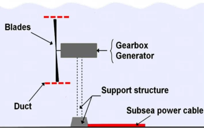
Tidal Current systems are in the first steps of their industrial deployment. The first tidal stream systems are broadly similar to submerged wind turbines. Most technologies of tidal energy converters use similar configurations as those used in the wind turbines in order to benefit of the many years of operational experience in the wind industry. Thus, the system is composed typically of: turbine, gearbox (or not if a direct driven system is used), generator with his converter and support structure (Figure 3).
Figure 1. Tide velocity at Penmarc’h, France, in 2010
There are two main families of turbines depending on the axis of rotation direction: horizontal axis turbines (or axial flow) and vertical axis turbines (transverse flux turbines). These are the most studied and most tested technologies, although the majority of industrial concepts utilize horizontal axis turbines [5] (Figure 4).
A duct system can be used around the blades to concentrate the flow towards the blades and reduce turbulence effects which improve the power conversion efficiency of the turbine.
Support structure used to hold the different tidal stream systems are of several types: gravity base, pile or floating system depending of the site characteristics [6].
An offshore power substation and cable will connect generator to the electrical grid.
The generator can be an induction generator or a permanent magnet synchronous generator.
A gearbox can be used to increase the speed of the generator’s rotor shaft to minimize the constraints on the generator design (minimizing the rated torque of the machine). However the use of a gearbox leads to severe maintenance constraints because a regular lubrication is needed and gearbox is one of the main downtime causes in this kind of systems. In such case it is necessary to investigate technological solution to access more easily to the turbines as in Seagen Project which includes a system to lift the turbine over the surface (Figure 4 (b)).
However tidal stream systems require high reliability to reduce maintenance operations in sites difficult to access. The simple and robust technologies are preferred for this type of application. The challenge is to maximize the reliability and robustness of the different components of a tidal system. This pushes to consider the use of simple structures with minimum possible mechanisms.
Use of geared solution introduces a decrease in efficiency and increase in operational and maintenance costs and constraints which is a key feature in offshore renewable energy converters [7]. The elimination of mechanical gearbox can be an attractive solution because it allows the minimization of maintenance. Systems with direct drives based on low speed permanent magnets generators can be particularly useful for these applications [8] [9] because this technology allows building low speed high torque density and generators with high number of poles. Many industrial developers have constructed direct drive tidal turbines such as OpenHydro company [10] and CleanCurrent [11].
This paper focus on a new kind of PM generator which uses a passive solid rotor and is based on saliency effects. This kind of generator is called “Double Salient Permanent Magnet” Generator (DSPM) and can fit to the tidal energy specifications and constraints.
Figure 3. The different elements of a tidal stream system
(a) OpenHydro (b) SeaGen
(c) CleanCurrent (d) Tidal Generation Limited Figure 4. Industrial tidal stream systems
We will present the study and the analysis of this new concept of generator.
Firstly, the structure of the generator has been introduced. Then, an electromechanical model will be presented. This model allows to link electrical equation based on inductance and PM flux calculation and electromagnetic torque. Finite element method is used for computing the magnetic fluxes distribution.
From the magnetic flux distribution the inductance is calculated with different methods and a new method has been developed to take into account more accurately saturation effects. This new method will allow obtaining a more accurate electromechanical model which can be used for modeling and design of this kind of machine.
II. DESCRIPTION OF THE DSPM GENERATOR
Various studies show that adjoining permanent magnets with variable reluctance machines, allow to identify new structures with improved performance. Many structures of machines which are called “doubly salient permanent magnet” (DSPM) have been studied in the literature over the last decade [12-17].
The DSPM that we propose to study is a structure with small trapezoidal teeth excited by four NdFeB magnets housed in the stator yoke. This structure includes three phases consisting of simple concentric winding. The structure has 48 stator small teeth located in 12 large teeth (4 large teeth per phase). On the other hand, the rotor has 64 small teeth similar to the rotor ones. The complete machine is shown in Fig.3.
The DSPM has the advantage of great simplicity of construction and robustness. This structure can produce a high torque. In addition, the absence of excitations in the rotor reduces the thermal stresses because losses are mainly located in the stator which is easier to cool. So compared to various structures dedicated to direct drive (low speed and high torque) the DSPM can be an interesting alternative for direct drives [18].
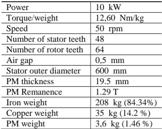
The details dimensions of the proposed DSPM generator topology analyzed in this paper are shown in Table 1. The machine is designed for a rated operating point at turning speed (50 rpm). This rated point corresponds to a low power experimental tidal turbine specification.
(a) 3D view (b) Cross-section Figure 5. Structure of DSPM Power 10 kW Torque/weight 12,60 Nm/kg Speed 50 rpm Number of stator teeth 48 Number of rotor teeth 64 Air gap 0,5 mm Stator outer diameter 600 mm PM thickness 19.5 mm PM Remanence 1.29 T
Iron weight 208 kg (84.34%) Copper weight 35 kg (14.2 %) PM weight 3,6 kg (1.46 %)
Table 1. Specifications of the DSPM
This configuration corresponds to a small experimental tidal turbine dimensioned for a rated current of 1.95 m/s. The turbine will reach a power coefficient of 0.4 with a TSR (Tip Speed Ratio) optimum of 4. The power level associated with this specification was chosen to enable the implementation and testing of the machine in laboratory environment.
III. MODELLING AND BASIC PRINCIPLE
The electrical equation is obtained by the application of Faraday's Law to each winding. We can write:
Where R : resistance of a stator winding i : current per phase
: total flux per phase
The total magnetic flux Ψ per phase is composed of the flux of the magnets and the flux of armature reaction :
The expression of electromagnetic torque per phase can then be evaluated by:
(∫ ) ( ) ⏟ ( ) ⏟
Where the stator inductance matrix the mechanical angle reluctance torque hybrid torque
cogging torque
In our case the cogging torque can be neglected [19]. Then the torque of the machine has two components: a hybrid
torque due to the action of magnets on current (torque of
the same type as the main EM torque of a conventional PM generator) and a couple associated with variable reluctance. The main couple is the hybrid torque. The reluctant torque appears as a disturbance.
Figure 6. Basic principle operating for one-phase-on
To illustrate the operating principle, theoretical waveforms are shown in Figure 6 for a rectangular current supply controlled according to the position by a PWM inverter. A torque is obtained by applying a positive current when the magnets flux increases and a negative current when the flux decreases.
In this simplified approach, the inductance and magnets flux variations are assumed to be linear and only depend on the position as shown in Figure 3. In real operation, these variations also depend on magnetic saturation which occurs in this kind of structure. It is thus observed reading of equations (1) to (3) that the knowledge related to the magnets flux and machine inductances in saturated regime are essential for estimating the performance of the machine. As examples an accurate model is necessary to calculate the EM torque and adapt the machine characteristics to the converter. These parameters vary depending on the level of saturation of the magnetic circuit. Therefore the model of the machine changes as well. This is why the rest of the paper is devoted to the calculation of inductances when the magnetic circuit of the machine is saturated.
IV. CALCULATION OF INDUCTANCES IN SATURATED MODE
The determination of the inductances allows to know precisely the importance of the saturation effects. A 2D finite element analysis has been applied to study the variations of inductances and see the effect of the geometry of the machine (saliency) and the effect of excitations (current / magnets) on these variations.
Figure 8 shows the PM flux linkage of DSPM at no-load determined The EMF can be deduced of this flux linkage by:
Where is the back EMF, is the PM flux linkage, is
the rotor angle and is the angular speed of rotor.
Figure 7. magnetic flux density map in conjunction position of phase A
Figure 8. Characteristics of DSPM : PM flux linkage and EMF waveforms
We present two methods for calculating inductances used in the literature, and an original method to take into account the saturation effects (Figure 9).
A. Method 1
The magnets are replaced by passive material which has the permeability of the magnet. The coils are fed and inductances are calculated from flux and currents according to the relationship [19-20]:
Of course; this method does not take into account the increase of the saturation level due to the presence of magnets.
B. Method 2
The flux created by the magnets at no load, is subtracted from the total flux in load operations (flux created by both magnets and currents) [12-14].
This method adds flux in saturated materials. This appears to be not physically correct because only magneto-motive forces should be added in this case.
C. Method 3
We propose an original method of replacing the magnets with an equivalent magnetomotive force (MMF). First, we quantify the flux due to the magnets at no load which crosses the phase at all the positions. The next step is to find the current leading to the same flow using
Figure 9. The 3 methods used to calculate inductances
Then we add these currents (associated with the positions of the rotor) to the current for which we want to calculate the inductances. Finally, for each position of the rotor we calculate the flux in phase i by varying the current
.
The inductance is then determined by:
The self-inductance of phase A of the DSPM is calculated on linear mode (unsaturated) and different levels of saturated magnetic circuit conditions using the finite element method by the three methods (Figure 10).
In the linear regime, the 3 methods lead to the same result. In saturated regime (I = 10A, 40A and 100A), differences appears between the results depending on the position.
The inductance calculation is particularly affected by magnetic saturation in conjunction position when the teeth are facing to each other (180°). We observe, however, that when the saturation increases, Method 2 results in an unexpected reduction in the inductance at conjunction position (180 °). So the third method which is original seems to be the more accurate and seems to allow taking into account the saturation effects in better way. This better accuracy has to be confirmed by comparison with experimental results in future works.
V. CONCLUSION
In this paper, we have presented a structure of doubly salient generator with permanent magnets placed in the stator. This concept uses a simple and robust structure, with passive rotor witch can satisfy the specific requirements of direct driven tidal current generator. An electromechanical model of this machine is presented. The use of this model is based on the accurate calculation of inductances in saturation mode. An original method determining these inductances was presented from FEA calculation. The values of the inductance can have significant differences depending on the method used to calculate them. This can make it difficult to predict performance during an actual state of operation. Therefore, the performances of the machine using each method should be determined and compared and validated by comparison with experimental results.
Linear mode Ia=10A
Ia=40A Ia=100A
Figure 10. Self-inductance of phase A of the DSPM
REFERENCES
[1] J. F. Manwell, J. G. McGowan, A. L. Rogers “Wind Energy Explained: Theory, Design and Application, Second Edition Chichester”, U.K. : Wiley, 2009. ISBN: 9780470015001
[2] Hamed H. H. Aly, M. E. El-Hawary. “Comparative Study of Stability Range of Proposed PI Controllers for Tidal Current Turbine Driving DFIG”. International Journal of Renewable and Sustainable Energy. Vol. 2, No. 2, 2013, pp. 51-62.
[3] P. Frankel, “Tidal Current Energy Technologies,” Ibis, vol. 148, pp. 145–151, Mar. 2006.
[4] Chen, H.; Ait-Ahmed, N.; Zaim, E. H.; Machmoum, M., "Marine tidal current systems: State of the art," Industrial Electronics (ISIE), 2012 IEEE International Symposium on , vol., no., pp.1431,1437, 28-31 May 2012
[5] King, J.; Tryfonas, T., "Tidal stream power technology - state of the art," OCEANS 2009 - EUROPE , vol., no., pp.1,8, 11-14 May 2009 [6] P. L. Fraenkel Power from marine currents Proceedings of the Institution
of Mechanical Engineers, Part A: Journal of Power and Energy February 1, 2002 216: 1-14,
[7] Keysan, O.; McDonald, A.; Mueller, M. Integrated Design and Optimization of A Direct Drive Axial Flux Permanent Magnet Generator for A Tidal Turbine. In Proceedings of the International Conference on Renewable Energies and Power Quality-ICREPQ, Granada, Spain, 23– 25 March 2010.
[8] Keysan, Ozan; McDonald, A.S.; Mueller, M., "A direct drive permanent magnet generator design for a tidal current turbine(SeaGen)," Electric Machines & Drives Conference (IEMDC), 2011 IEEE International , vol., no., pp.224,229, 15-18 May 2011
[9] Benelghali, S.; Benbouzid, M.E.H.; Charpentier, J.F., "Generator Systems for Marine Current Turbine Applications: A Comparative Study," Oceanic Engineering, IEEE Journal of , vol.37, no.3, pp.554,563, July 2012
[10] OpenHydro [Online]. Available: http://www.openhydro.com [11] Clean Current [Online]. Available: http://www.cleancurrent.com [12] L. Yuefeng; L. Feng; T.A. Lipo; "A novel permanent magnet motor with
doubly salient structure", Industry Applications, IEEE Transactions on , vol.31, no.5, pp.1069-1078, Sep/Oct 1995.
[13] F. Ying; K.T. Chau; M. Cheng; "A new three-phase doubly salient permanent magnet machine for wind power generation", Industry Applications, IEEE Transactions on, vol.42, no.1, pp. 53-60, 2006. [14] M. Cheng, K.T. Chau and C.C. Chan, “Design and analysis of a new
doubly salient permanent magnet motor,” IEEE Trans. on Magnetics, vol. 37, no. 4, pp. 3012-3020, 2001.
[15] J. Zhang, M. Cheng, Z. Chen, W. Hua, “Comparison of stator-mounted permanent-magnet machines based on a general power equation,” IEEE Trans. on Energy Conv., vol. 24, no. 4, pp. 826-834, 2009.
[16] J. Zhang, M. Cheng, Y. Zhang, “Single phase doubly salient permanent magnet generator with full-pitched winding,” Inter. Electric Machines and Drives Conf., Miami Florida, pp. 311-316, 2009.
[17] X. Zhu, M. Cheng, W. Hua, J. Zhang, W. Zhao, “Design and analysis of a new hybrid excited doubly salient machine capable of field control,” IEEE 41th IAS Annual Meeting, Tampa Florida, pp. 2382-2389, 2006.
[18] M. Machmoum, L. Moreau, M. Zaïm, J. Azzouzi, G. Barakat, N.Takorabet, Ch. Chillet, D. Matt, S. Taïbi, A. Tounzi, Ch.Espanet, A. Miraoui, H. S. Zire, " Comparaison de structures électromagnétiques pour une application en générateur à faible vitesse et fort couple " Revue Internationale de Génie Electrique(RIGE), Vol. 8, n°2, pp. 287-330, Mai 2005.
[19] R. Saou ; " Modélisation et optimisation de machines lentes à aimants permanents : Machines à double saillance et à inversion de flux ", Thèse de Doctorat, Ecole Nationale Polytechnique d’Alger, Novembre 2008. [20] L. Moreau ; " Modélisation, conception et commande de génératrices à
réluctance variable basse vitesse ", Thèse de Doctorat, Ecole Polytechnique de l’Université de Nantes, Décembre 2005.
[21] A. Rezzoug ; M.E. Zaïm; "Machines électriques non conventionnelles ", Ed.Hermes Science-Lavoisier,261pages,2011.ISBN 978-2-7462-2574-9.