HAL Id: tel-01382345
https://hal-lirmm.ccsd.cnrs.fr/tel-01382345
Submitted on 16 Oct 2016HAL is a multi-disciplinary open access
archive for the deposit and dissemination of sci-entific research documents, whether they are pub-lished or not. The documents may come from teaching and research institutions in France or abroad, or from public or private research centers.
L’archive ouverte pluridisciplinaire HAL, est destinée au dépôt et à la diffusion de documents scientifiques de niveau recherche, publiés ou non, émanant des établissements d’enseignement et de recherche français ou étrangers, des laboratoires publics ou privés.
Exploiting Model Transformation Examples for Easy
Model Transformation Handling (Learning and
Recovery)
Hajer Saada
To cite this version:
Hajer Saada. Exploiting Model Transformation Examples for Easy Model Transformation Handling (Learning and Recovery). Software Engineering [cs.SE]. Université Monpellier 2, 2013. English. �tel-01382345�
Académie de Montpellier
Université Montpellier
2
Sciences et Techniques du Languedoc LIRMM
Ph.D Thesis
présentée au Laboratoire d’Informatique de Robotique et de Microélectronique de Montpellier pour
obtenir le diplôme de doctorat
par
Hajer Saada
Spécialité : Informatique
Formation Doctorale : Informatique
École Doctorale : Information, Structures, Systèmes
Exploiting Model Transformation Examples
for Easy Model Transformation Handling
(Learning and Recovery)
Soutenue le 04/12/2013, devant le jury composé de :
Reviewers
Gertrude Kappel, Professeur . . . University of Technology, Vienne, Autriche Benoit Baudry, Chargé de Recherches HDR, . . INRIA Rennes Bretagne Atlantique, France
Examinator
Marie-Pierre Gervais, Professeur . . . . Université Paris Ouest Nanterre La Défense , France
Supervisor
Marianne Huchard, Professeur . . . Université Montpellier 2, France
Joint supervisor
Clémentine Nebut , Maitre de Conférences . . . Université Montpellier 2, France Houari Sahraoui , Professeur . . . Université de Montréal, Canada
iii
Acknowledgements
The research work presented in this thesis has been performed in the Laboratoire d’Informatique de Robotique et de Microélectronique de Montpellier (LIRMM), University Montpellier 2. This thesis has been done in collaboration between University Montpellier 2 and University of Montreal. My stay in France for pursuing the doctorate degree has been financially supported by the Government of Tunisia.
My first and sincere acknowledge goes to my supervisors Marianne Huchard, Clémen-tine Nebut and Houari Sahraoui for all I have learned from them and for their continuous help and support in all stages of this thesis. I would like to thank them for encouraging and helping me to shape my interest and ideas, and especially for letting me wide autonomy while providing appropriate advice. It was a real pleasure to work with them.
I would like to express my gratitude to the honorable reviewers, Dr. Gertrude Kappel and Dr. Benoit Baudry for accepting to review my thesis. I am thankful for their valu-able comments and remarks. I am grateful to Dr. Marie-Pierre Gervais for her thorough examination of the thesis.
As a member of MaREL team, I got a lot of help and encouragement from all the members of the group. I forward my extreme appreciations to all MaREL members.
My greatest acknowledge goes to my closest friend Mohamed for the continuous help and advice, and for his effort in proof reading the thesis drafts and providing valuable feedback.
Thanks to my supportive friends, Najib, Kaouthar, Nadia, Xavier, Naoufal, Amine, Zak, Younes, Anas, Seza, Hamzeh, Raafat, Thibaut, Petr, Sarra, Azhar, Adel, Julien, Zakaria, and others who made the lab a friendly environment for working.
Thanks to my friends in the university of Tunisia, Jamel, Asma, Siwar, Nesma, Nesrine, Halima, Zeineb, Takwa..
Last but not the least, I would like to thank my mother and my father for always believing in me, for their continuous love and their supports in my decisions. I am also very grateful to my brothers, my sisters, my nieces and nephews.
Hajer Saada December 2013
Abstract
Model Driven Engineering (MDE) considers models as first class artifacts. Each model con-forms to another model, called its metamodel which defines its abstract syntax and its semantics. Various kinds of models are handled successively in an MDE development cycle. They are ma-nipulated using, among others, programs called model transformations. A transformation takes as input a model in a source language and produces a model in a target language. The developers of a transformation must have a strong knowledge about the source and target metamodels which are involved and about the model transformation language. This makes the writing of the model transformation difficult.
In this thesis, we address the problem of assisting the writing of a model transformation and more generally of understanding how a transformation operates. We adhere to the Model Transformation By Example (MTBE) approach, which proposes to create a model transformation using examples of transformation. MTBE allows us to use the concrete syntaxes defined for the metamodels. Hence, the developers do not need in-depth knowledge about the metamodels. In this context, our thesis proposes two contributions. As a first contribution, we define a method to generate operational transformation rules from transformation examples. We extend a previous approach which uses Relational Concept Analysis as a learning technique for obtaining transformation patterns from
1-1 mapping between models. We develop a technique for extracting relevant transformation rules
from these transformation patterns and we use the JESS language and engine to make the rules executable. We also study how we better learn transformation rules from examples, using trans-formation examples separately or by gathering all the examples. The second contribution consists in recovering transformation traces from transformation examples. This trace recovery is useful for several purposes as locating bugs during the execution of transformation programs, or checking the coverage of all input models by a transformation. In our context, we expect also that this trace will provide data for a future model transformation learning technique. We first address the trace recovery problem with examples coming from a transformation program. We propose an approach, based on a multi-objective meta-heuristic, to generate the many-to-many mapping between model constructs which correspond to a trace. The fitness functions rely on the lexical and structure simi-larity between the constructs. We also refine the approach to apply it to the more general problem of model matching.
Keywords: MDE, model transformation, MTBE, operational rules, model transformation traces, model
matching, FCA, JESS, meta-heuristic, genetic algorithm.
Résumé
L’Ingénierie Dirigée par les Modèles (IDM) est un domaine de recherche en pleine émergence qui considère les modèles comme des éléments de base. Chaque modèle est conforme à un autre modèle, appelé son méta-modèle, qui définit sa syntaxe abstraite et ses concepts. Dans un processus IDM, différents types de modèles sont manipulés par des transformations de modèles. Une trans-formation génère un modèle dans un langage cible à partir d’un modèle dans un langage source. Pour concevoir une transformation, les développeurs doivent avoir une bonne connaissance des méta-modèles concernés ainsi que des langages de transformation, ce qui rend cette tâche difficile. Dans cette thèse, nous proposons d’assister l’écriture des transformations et plus généralement de comprendre comment une transformation opère. Nous adhérons à l’approche de transformation de modèles par l’exemple qui propose de créer une transformation de modèles à partir d’exemples de transformation. Cela permet d’utiliser la syntaxe concrète définie pour les méta-modèles, et cela évite donc de requérir que les développeurs aient une bonne maîtrise des méta-modèles utilisés. Dans ce contexte, nous proposons deux contributions. La première consiste à définir une méthode pour générer des règles de transformation opérationnelles à partir d’exemples. Nous nous basons sur une approche qui utilise l’Analyse Relationnelle de Concepts (ARC) comme technique d’ap-prentissage pour obtenir des patrons de transformation à partir d’un appariement de type 1-1 entre les modèles. Nous développons une technique pour extraire des règles de transformation opéra-tionnelles à partir de ces patrons. Ensuite, nous utilisons le langage et le moteur de règles JESS pour exécuter ces règles. Nous étudions aussi comment mieux apprendre des règles de transformations à partir d’exemples, en utilisant séparément chaque exemple ou en réunissant tous les exemples. La deuxième contribution consiste à récupérer les traces de transformation à partir d’exemples de transformation. Ces traces peuvent être utilisées par exemple pour localiser des erreurs durant l’exé-cution des programmes de transformation ou vérifier la couverture de tous les modèles d’entrée par une transformation. Dans notre contexte, nous supposons que ces traces vont servir pour un futur apprentissage des règles de transformation. Nous traitons tout d’abord le problème de récupéra-tion des traces avec des exemples provenant d’un programme de transformarécupéra-tion. Nous proposons une approche basée sur une méta-heuristique multi-objectifs pour générer des traces sous forme d’appariement de type n-m entre des éléments de modèles. La fonction objectif s’appuie sur une similarité lexicale et structurelle entre ces éléments. Une extension de cette méthode est proposée pour traiter le problème plus général de l’appariement entre modèles.
Mots clefs : IDM, transformation de modèles, l’approche par exemple, règles opérationelles, traces de
trans-formation, appariement des modèles, AFC, JESS, meta-heuristique, algorithmes génétiques
Contents
Acknowledgements v
Abstract (English/Français) vii
Contents xi
Introduction 3
1 Preliminaries 7
1.1 Formal Concept Analysis and Relational Concept Analysis. . . 7
1.2 Java Expert System Shell . . . 12
1.3 The NSGA-II Algorithm . . . 13
2 State Of The Art 17 2.1 Model Driven Engineering. . . 17
2.2 Model Transformation . . . 20
2.2.1 Model Transformation Classification. . . 20
2.2.2 Model Transformation Languages . . . 23
2.3 Towards Model Transformation Generation . . . 24
2.3.1 Meta-model Matching for Model Transformation Generation . . . 24
2.3.2 Model Transformation By Example . . . 26
2.3.2.1 MTBE approaches . . . 26
2.3.3 Synthesis. . . 28
2.4 Model Transformation Traceability . . . 29
2.4.1 Summary . . . 31
2.5 Search Based Software Engineering . . . 32
2.6 Conclusion . . . 33
3 Generation of Operational Transformation Rules from Examples of Model Trans-formations 35 3.1 Introduction . . . 36
3.2 Overview of the Rules Generation and Execution . . . 37
3.3 A By-example Approach to Obtain Transformation Patterns . . . 39
3.3.1 Obtaining the Transformation Patterns . . . 39
3.3.2 Patterns Lattice Simplification . . . 45
3.3.3 Rules Generation . . . 47
3.3.3.1 Meta-models2Templates . . . 48
3.3.3.2 Models2Facts . . . 49
3.3.3.3 TransformationPatterns2JessRules. . . 50
3.3.4 Tool Support and Case study . . . 51
3.4 Strategies for learning Model Transformations from Examples . . . 54
3.4.1 Discussion . . . 59
3.4.2 Summary . . . 59
3.5 Conclusion . . . 60
4 Model Transformation Traceability and Model Matching: metaheuristic approaches 61 4.1 Introduction . . . 62
4.2 Approach Overview . . . 63
4.2.1 Problem Statement . . . 63
4.2.2 Approach Overview . . . 65
4.3 Adapting NSGA-II to the Transformation Trace Recovery Problem . . . 68
4.3.1 Solutions Representation . . . 68 4.3.2 Solutions Evaluation . . . 69 4.3.3 Operators Definition . . . 71 4.4 Evaluation . . . 73 4.4.1 Experimental Setting . . . 73 4.4.1.1 Experimental data . . . 73 4.4.1.2 Experimental protocol . . . 74
4.4.2 Results and Discussion . . . 76
4.4.2.1 Results for the six examples . . . 76
4.4.2.2 Detailed results for the Cl2Rs example . . . 78
4.4.2.3 Performance . . . 79
4.4.3 Threats to Validity . . . 80
4.5 The Model Matching Problem . . . 81
4.5.1 Evaluation . . . 82
4.6 Conclusion . . . 84
Conclusions and perspectives 87
Bibliography 93
List of Figures 103
List of Tables 105
Contents 1
Acronyms
MDE:Model Driven Engineering
UML:Unified Modeling Language
MDA:Model Driven Architecture
MT:Model Transformation
MTBE:Model Transformation By Example
OMG:Object Management Group
MOF:Meta-Object Facility
CIM:Computation Independent Model
PIM:Platform Independent Model
PSM:Platform Specific Model
MT:Model Transformation
RS:Relational Schema
CD:Class Diagram
API:Application Programming Interface
VB:Visual Basic
LHS:Left-Hand Side
RHS:Right-Hand Side
OCL:Object Constraint Language
MTBE:Model Transformation By Example
ILP:Inductive Logic Programming
RCA:Relational Concept Analysis
MTBD:Model Transformation By Demonstration
SBSE:Search Based Software Engineering
GA:Genetic Algorithms
SA:Simulated Annealing
PbE:Programming by Example
PSO:Particle Swarm Optimization
SA:Simulated Annealing
Introduction
Research Context
Model Driven Engineering (MDE) [Schmidt, 2006] is a software development method-ology which focuses on creating and exploiting models. MDE involves different princi-ples including OMG’s Model Driven Architecture (MDA) [Soley and the OMG Staff Strat-egy Group, 2000], that is based on the separation of business logic from platforms tech-nology. One basic principle of MDE is "everything is a model". MDE provides supports for creating and editing models, transforming models to other models or programs, model-based testing, etc. The use of models helps to improve the productivity by maximizing compatibility between systems (via model reuse), the simplification of the process design and the communication between developers (via standardization) [Schmidt, 2006]. Each model conforms to another model, called its metamodel, which defines the structure, i.e., concepts and their relationships that can be used to compose a model.
Besides models, model transformations represent another crucial element of MDE. They allow the definition of mapping between models. Transformations aim to automate the translation within and between different modeling languages, e.g., the transformation of a design model to a program in C#. Transformations are defined at the metamodel level, and are applied at the model level. They transform a model in a source language to a model in a target language. For this end, models must be written in a modeling language (e.g., the Unified Modeling Language - UML). A modeling language corresponds also to a metamodel (e.g., UML metamodel) which defines the language concepts. Based on the modeling language, we can distinguish between two types of transformation: exogenous transformation and endogenous transformation [Mens and Gorp, 2006].
An exogenous transformation is a transformation between source and target models expressed using different languages, e.g., the transformation of a UML class diagram to a Java code. Endogenous transformation is a transformation between source and target models expressed in the same language, e.g., for maintenance activities (refactoring or optimization). It rewrites the input model to produce the output model for renaming,
4 Introduction
adding or deleting some of its constructs. An endogenous transformation serves to change the structure of software without changing its behavior.
Thesis Problem
Several languages have been proposed to write model transformations. Although most of these languages are able to implement complex transformation problems, it may be dif-ficult to use them for individuals who are not expert on specific transformation languages. In addition, the solution domain of a model transformation (abstract syntax of modeling languages) can be different from the problem domain (concrete syntax). Domain experts often give more easily transformation examples than complete and consistent transforma-tion rules [Kessentini, 2010].
In this thesis, we stand for the idea that the high quality and the multiplicity of transfor-mation examples may be exploited to assist the designers to write model transfortransfor-mation. Moreover, we believe that this assistance must be based on two main focuses:
1. An assistance for the definition of operational transformation rules which constitute the body of the transformation.
2. An assistance for the extraction of mapping links between source and target model of the transformation to infer a trace of the transformation.
Contributions
Our contribution deals with the assistance of model transformation by example design. More specifically, we provided solutions for two specific problems: 1) the definition of operational rules which constitute the transformation and 2) the extraction of links between the source and target models of the transformation.
Generation of operational transformation rules: We propose an approach to generate model transformation rules from transformation examples. Examples are given by experts. An example consists of a source model, a target model and the mapping between the two models. Our work is a continuation of the approach of Dolques et al. [Dolques et al., 2009], that uses Relational Concept Analysis [Huchard et al., 2007], as a learning technique, to derive transformation patterns organized in a lattice. Those patterns are abstract and they cannot be executed. Moreover, some of them are not relevant. Thus, we define in this first contribution an approach to analyze those patterns and select the most pertinent ones.
Introduction 5
Furthermore, we propose a method to transform them into operational transformation rules written for the Java Expert System Shell (Jess) rule engine [Hill, 2003].
We also study how we better learn transformation rules using transformation examples. Thus, we perform experimentations to compare two learning strategies. While the first strategy uses examples separately to generate rules, the second one gathers all examples together and generates rules.
Recovering model transformation traces: As a second contribution of this thesis, we propose to generate fine-grained mappings from examples issued from a transformation. The transformation may be done or edited manually by experts. Thus recovering traces between models may be very essential in a development cycle to track their changes. For this end, we define an approach to derive many-to-many mapping between model elements. Our approach takes as input a source model in the form of a set of fragments (fragments are defined using the source metamodel cardinalities and Object Constraint Language (OCL) constraints), and a target model. It searches for each source a set of target elements by maximizing the lexical and structural similarities between them. Hence, it may lead to a huge number of possible combinations. Thus, NSGA-II, a metaheuristic method , is used to solve this problem.
The problem of transformation traces recovery may be similar to the model matching one. In the first context, source and target models are issued from a transformation program. Hence, it is easy to discover lexical similarities between the models constructs. However, if the transformation between source and target models is done manually, this may cause lexical and structural variations between the two models. Thus, the problem may be ad-dressed in a model matching context.
We have consequently defined a variant of the model transformation recovery approach to deal with the model matching problem. The lexical similarity function is performed using a natural language process. Our approach produces matchings of type many-to-many between models.
Thesis Outline
This dissertation is organized as follows:
Chapter 1 introduces the techniques and tools used in this work. Definitions about Formal Concept Analysis and Relational Concept Analysis are given. Then, we present the
6 Introduction
JESS rule engine. Finally, an overview on metaheuristic methods is presented and more details are given about NSGA-II, which is used in our second contribution.
Chapter 2provides a literature review of the state of the art in model driven engineer-ing, model transformation, model transformation traceability and search-based software engineering.
Chapter 3reports our contribution for generating operational transformation rules from examples. An overview of the approach is given including the application of RCA to ob-tain the patterns, the selection of relevant patterns and the transformation of patterns into operational rules. Then, we explain how to write and execute model transformations with the Jess rule engine. Experimental evaluations are also presented to compare two strategies of model transformation learning. The first strategy consists in learning model transforma-tions separately from different examples and the second one consists in gathering examples to learn transformation rules.
Chapter 4presents our approach, which is based on metaheuristic methods, to address the transformation trace recovery problem as an optimization problem. After the problem definition, we describe how to adapt, a chosen meta-heuristic, NSGA-II to the recovery of traces from transformation examples. Then, we extend this approach to the model matching problem. Experimental evaluations are presented to validate our approaches.
Finally, we conclude this dissertation and we highlight some future directions of re-search.
1
Preliminaries
I
n this chapter, we introduce the techniques and tools used in this work. We introduce the definitions needed to understand Formal Concept Analysis and Relational Concept Analysis which will be used for transformation pattern learning. Then, we present the Java Expert System Shell rule engine which helps us making operational the transformation rules. Finally, a summary of the existing meta-heuristic methods is presented and more details are given about NSGA-II, the meta-heuristic we have chosen for addressing the problem of model transformation trace recovery.1.1
Formal Concept Analysis and Relational Concept Analysis
Formal Concept Analysis (FCA) [Ganter and Wille, 1999] is a mathematical theory, based on lattice theory, which is used for machine learning, data mining, or knowledge structuring, as it groups entities described by characteristics into concepts, ordered in a lattice structure. Relational Concept Analysis (RCA) [Huchard et al., 2007] is an extension of FCA to relational data. While FCA produces a single classification, using a formal context, RCA computes several connected classifications (lattices), using a relational context family.
Definition 1.1 (Formal context): A formal context is a triple K = (O, A, R) where O and A are sets (objects and attributes, respectively) and R is a binary relation, i.e., R ⊆ O×A.
Table 1.1 presents a formal context where several animals are described by their char-acteristics. A formal concept is a pair (E, I) composed of an object set E ⊆ O and their shared attribute set I ⊆ A.
E = {o ∈ O|∀a ∈ I,(o, a) ∈ R} is the extent of the concept, while I = {a ∈ A|∀o ∈ E,(o, a) ∈ R} is the intent of the concept. For example, ({f lamingo, chicken}{f lying, f eathered})is a concept of our example.
8 Chapter 1. Preliminaries
flying nocturnal feathered migratory with_crest with_membrane
flying squirrel × ×
bat × × ×
ostrich ×
flamingo × × ×
chicken × × ×
Table 1.1 – A formal context for describing animals
Given a formal context K = (O, A, R), and two formal concepts C1 = (E1, I1) and
C2 = (E2, I2) of K, the concept specialization order≤s is defined as follows: C1 ≤s C2 if
and only if E1 ⊆ E2 (and equivalently I2 ⊆ I1). C1 is called a sub-concept of C2. C2 is
called a super-concept of C1. For example, ({f lamingo, chicken}{f lying, f eathered}) is a
sub-concept of ({f lamingo, chicken, ostrich}{f eathered}).
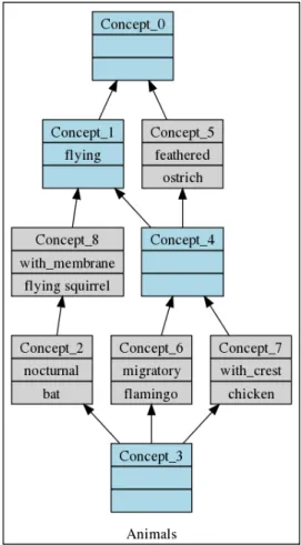
LetCKbe the set of all concepts of a formal context K. This set of concepts provided with the specialization order (CK,≤s) has a lattice structure, and is called the concept lattice
as-sociated with K. Figure 1.1shows the Hasse diagram of the concept lattice structuring our animals. In this diagram, extents and intents are presented in a simplified form: removing up-down inherited attributes and down-up inherited objects. It describe several concepts, e.g., Concept_4, which groups the flying and feathered animals (flamingo, chicken) or Con-cept_5 which groups the feathered animals (flamingo, chicken and ostrich). The lattice highlights the structure of data: e.g. the group of flying animals is distinct of the group of feathered animals, implication rules can be extracted, like being with-crest implies being feathered (because Concept_7 is a subconcept of Concept_5).
While FCA builds upon a formal context, with a unique object set and a unique attribute set, RCA elaborates upon a relational context family, close to an entity-relationship model.
Definition 1.2(Relational Context Family): A Relational Context FamilyF is a pair(K, R)with: • K is a set of object-attribute contexts Ki = (Oi, Ai, Ii), i ∈ 1..n where Oi is a set of objects,
Ai is a set of attributes and Ii ⊆Oi×Ai.
• R is a set of object-object contexts Rj = (Ok, Ol, Ij), where (Ok, Ol) are the object sets of
formal contexts(Kk, Kl) ∈ K2, Ij ⊆ Ok×Ol and Kk is the source/domain context, Kl is
the target/range context.
One main principle of RCA consists in integrating the relations between objects as relational attributes that link objects of an object-attribute context to concepts formed on another object-attribute context. Given an object-object context Rj = (Ok, Ol, Ij), there are
1.1. Formal Concept Analysis and Relational Concept Analysis 9
Figure 1.1 – The concept lattice for the formal context of Table1.1
to obtain a relational attribute. Relational scaling is the process by which these links are established between objects and concepts.
There are several scaling operators, the most used are:
• Existential (∃): an object is linked (by Rj) to at least one object of the extent of a
concept: ∃(Rj(o), Extent(C))is true iff Rj(o) ∩Extent(C) 6=∅.
• Universal strict (∀∃): an object is linked (by Rj) only to objects of the extent of a
con-cept: ∀∃(Rj(o), Extent(C))is true iff Rj(o) ⊆Extent(C) ∧ ∃x∈ Rj(o), x∈Extent(C)
The RCA process is an iterative process which is sketched below.
RCA initialization step: Build, for i in 1..n, L0[i]the concept lattice of the contextK i. RCA Step p:
• apply the relational scaling to all object-object contexts using the lattices of step p−1 and the chosen scaling operators.
For Rj = (Ok, Ol, Ij), and the scaling operator S, this produces the scaled context
10 Chapter 1. Preliminaries
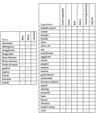
Pizza thin thick calzone okonomi × alberginia × margherita × languedoc × four-cheeses × three-cheeses × frutti-di-mare × quebec × regina × hawai × lorraine × kebab × Ingredient fruit-v egetable
meat fish dair
y cereal-leguminous veg-oil tomato-sauce × cream × tomato × basilic × olive × olive oil × soy × mushroom × eggplant × onion × pepper × ananas × mozza × goat-cheese × emmental × fourme-ambert × squid × shrimp × mussels × ham × bacon × chicken × maple-sirup × corn ×
Table 1.2 – Relational Context Family (RCF) / object-attributes contexts
has-topping tomato-sauce cream tomato basilic oliv
e oliv e oil so y
mushroom eggplant onion pepper ananas okonomi × × × × alberginia × × × × × margherita × × × × × languedoc × × × × × × × four-cheeses × three-cheeses × frutti-di-mare × × × quebec × regina × × hawai × × lorraine × × kebab × × × ×
Table 1.3 – Relational Context Family (RCF) / object-object context / part 1
– A is a set of relational attributes S Rj.C, where C is one concept of Lp−1[l], the
lattice built on objects of Ol at step p−1
– Ij contains (o, S Rj.C)iff S(Rj(o), Extent(C))is true.
• concatenate Ki with all the scaled relations R∗j whose domain is Oi, this gives an
extended contextKi∗
• update lattices of step p−1 to build, for i in 1..n, the lattice Lp[i]associated with the contextK∗i
The process stops when an iteration does not add any new concept and we consider the last lattice family obtained as the output of the process.
left-1.1. Formal Concept Analysis and Relational Concept Analysis 11
has-topping mozza goat-cheese emmental four
me-ambert
squid shr
imp
mussels ham bacon chicken maple-sir
up cor n okonomi alberginia margherita × languedoc × four-cheeses × × × × three-cheeses × × × frutti-di-mare × × × × quebec × × × × regina × × hawai × × lorraine × × kebab × ×
Table 1.4 – Relational Context Family (RCF) / object-object context / part 2
Pizza thin thick calzone okonomi × alberginia × margherita × languedoc × four-cheeses × three-cheeses × frutti-di-mare × quebec × regina × hawai × lorraine × kebab × has-topping ∃has-topping. Concept_ 7 ∃ has-topping. Concept_ 5 ∃ has-topping. Concept_ 6 ∃ has-topping. Concept_ 8 ∃ has-topping. Concept_ 9 ∃ has-topping. Concept_ 10 ∃ has-topping. Concept_ 11 ∃ has-topping. Concept_ 12 okonomi x x x alberginia x x x margherita x x x x languedoc x x x x four-cheeses x x three-cheeses x x frutti-di-mare x x x x x quebec x x x x x regina x x x x hawai x x x x lorraine x x x x kebab x x x x Table 1.5 – Existential relational attributes
hand table presents an object-attribute context describing pizzas and the right-hand table presents an object-attribute context describing ingredients. Table 1.3andTable 1.4present an object-object context where the pizzas are described by their toppings (ingredients).
After the existential scaling, we obtain the table, in the right hand ofTable 1.5, in which for example okonomi is associated to∃ has−topping.Concept6. They are associated because
in the relation has-topping, okonomi is associated with mushroom, which belongs to the extent of Concept6 (Figure 1.2). Thus okonomi is associated with at least one element of the extent
of Concept6. This table is concatenated to the Pizza table, recalled in the left hand of
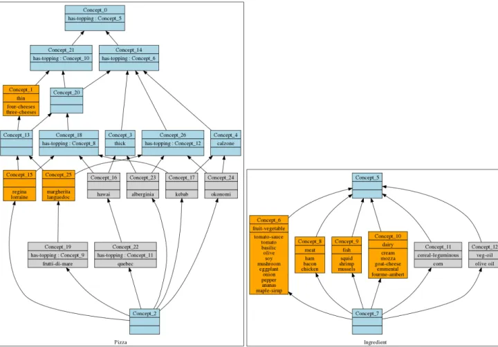
Table 1.5, to obtain the new Pizza lattice of Figure 1.2. For example, Concept_21 groups pizzas with at least one dairy topping (dairy ingredients are grouped in Concept_10). This is represented by the relational attribute ∃ has−topping : Concept_10 which is owned by pizzas from the extent of Concept_21. Concept_18 contains pizzas with at least one meat topping (relational attribute has−topping : Concept_8). Implication rules may also be
12 Chapter 1. Preliminaries
mined from this set of lattices. As Concept_18 is a sub-concept of Concept_21, we have ∃ has−topping : Concept_8 implies ∃ has−topping : Concept_10. This is interpreted by: having at least one meat topping implies having at least one dairy topping.
To conclude, while FCA is able to reveal structures in a single context, by building classifications and extracting implications rules from a single object set, RCA is able to build classifications and extracting implication rules from several object sets and links between these objects. Here we gave a simple example composed of only one relation, but RCA is able to deal with complex relational schemas, with several relations, and even cyclic relational schemas. The whole theoretical framework, with an analytical definition and a discussion about the convergence of the process are described in [Hacene et al., 2013].
Figure 1.2 – The obtained lattices for the pizza example
1.2
Java Expert System Shell
Java Expert System Shell (Jess) [Hill, 2003] is a rule engine integrated in the Java plat-form. Java code can be referred by Jess code [Daniele, 2006]. With Jess, we can create Java
1.3. The NSGA-II Algorithm 13
objects, implement Java interfaces, and call Java objects from its Java scripting environment. Despite this, Jess is mainly a declarative language.
A Jess program is usually composed of facts and rules. Facts encode data, while rules, activated by pattern matching, encode behavior [Hill, 2003]. A rule contains conditions, called left-hand-side (LHS), and actions, called right-hand-side (RHS). When the condition part is satisfied, the action part is executed. Conditions mainly test the presence of facts, whereas actions produce facts. Syntactically, a Jess rule is written as follows:
IF< (fact1)(fact2)...(factN) > THEN <(action1)(action2)...(actionM)>
The following example describes a very simple Jess rule which displays the name of each person who has a name.
1 (defrule welcome
2 (Person (firstname ?name))
3 =>
4 (printout t "Hello" ?name "!!!" crlf)
5 )
The conditions in LHS and facts conform to a template. A template in Jess is similar to a class in Java. It defines a fact type. A template has a name and a set of slots. A fact, i.e. a template instance, has specific values for these slots. The example below shows the declaration of Person template:
1 (deftemplate Person (slot firstname))
This example declares a template named Person with a property firstname. To instantiate a person fact, we use the command assert:
1 (assert (Person (firstname Peter)))
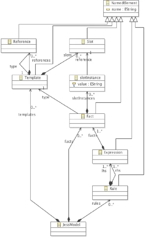
Figure 1.3 presents a simplified Jess metamodel. As mentioned above, a Jess model is composed of templates, facts and rules. A rule is composed of two expressions which present respectively the premise (LHS) and the conclusion (RHS). An expression contains a list of facts with conditions and tests defined on the facts themselves.
1.3
The NSGA-II Algorithm
During the past two decades, evolutionary algorithms (EAs) have gained popularity in dealing with software engineering tasks that could be modeled as optimization prob-lems. These problems are generally too complex to be solved using deterministic methods.
14 Chapter 1. Preliminaries
Figure 1.3 – Jess metamodel
EAs popularity could be explained by many reasons such as their simplicity, their appli-cability to a wide range of problems, as well as their ability to handle single and multiple objectives [Harman, 2011].
1.3. The NSGA-II Algorithm 15
chapter, it is usually difficult to find a single optimal solution. Such kind of problems gives rise to a whole set of solutions, known as Pareto-optimal solutions [Deb et al., 2002].
In this context, a number of multi-objective EAs have been proposed ([Horn et al., 1994;
Zitzler and Thiele, 1999;Knowles and Corne, 1999; Deb et al., 2002]). Among those algo-rithms, the non-dominated sorting genetic algorithm (NSGA-ii), proposed in [Deb et al., 2002], is the one that is the most applied in the Search Based Software Engineering (SBSE)
community [Harman et al., 2012]. We decided to use it in this work as it allows to easily model the trace recovery as a multiobjective optimization problem.
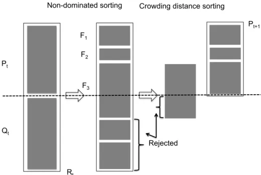
NSGA-II procedure. The evolution of the population during an iteration of the NSGA-ii procedure is presented in Figure 1.4 which is taken from the original paper. First, an initial population P0 of N solutions is created. The individuals of P0 are sorted based
on the non-domination. Non-dominated individuals, corresponding to the best known solutions (with regard to at least one objective) at the current step, are grouped in the first dominated front (rank 1). Discarding the individuals of the first front, the current non-dominated individuals form the second non-non-dominated front (rank 2), and so on. Diversity is preserved thanks to a crowding distance which is calculated for each solution [Laumanns et al., 2002]. Finally, a binary tournament selection operator, which is based on the crowding distance, selects the best solutions. At step t, an offspring population Qtof size N is created
using selection, crossover and mutation operators. Populations Pt and Qt are combined to
form the population Rt. From Rt, the best individuals in terms of non-dominance and
diversity are kept to form Pt+1. Then those steps are repeated till some termination criteria
are satisfied.
Fast non-dominated sorting principle. In order to identify solutions of the first non-dominated front in a population of size N, NSGA-ii calculates first, for each solution p: 1) the domination count np, i.e. the number of solutions which dominate the solution p, and
2) Sp, a set of solutions that the solution p dominates. A solution s1 dominates another solution s2 if: (i) s1 is no worse than s2 in all objectives, and (ii) s1 is strictly better than s2
in at least one objective.
In the first non-dominated front, there are the solutions which have their domination count equal to zero. For each solution p with np = 0, each member q ∈ Sp is visited,
and its domination count is reduced by one. Then, if the domination count of a member q becomes zero, q is put in a separate list Q. These members belong to the second non-dominated front. Then, this procedure is continued with the members of Q to identify the third front.
16 Chapter 1. Preliminaries Pt Qt F1 F2 F3
Non-dominated sorting Crowding distance sorting
Rejected
Rt
Pt+1
Figure 1.4 – NSGA-ii main (Deb et Al, 2002).
If Nobjis the number of objectives and N is the size of the population, this algorithm has
a low time complexity of O(NobjN2)compared to the previous algorithms, which require
O(NobjN3).
Diversity preservation.The parent and offspring populations (each of size N) are com-bined and evaluated to choose the best solutions. Then, the N best solutions are selected to form the next populations. As mentioned earlier, the solutions of the first front are selected and if there is a room, those of the second front are included, and so on. When the number of solutions in the already selected fronts is less than N, and including the next front results in exceeding N, the solutions of this last front have to be ranked, and only part of them is selected to complete the count. This is done by selecting solutions that are maximally apart from their neighbors according to the crowding distance. This is measured as the distance of the biggest cuboid containing the two neighboring solutions of the same non-dominating front in the objective space. The goal of the crowding-distance-based ranking is to increase the diversity of solutions that are injected into the next population. In Chapter 4, we will give more details about implementation of this algorithm for our problem.
2
State Of The Art
Contents
1.1 Formal Concept Analysis and Relational Concept Analysis. . . 7
1.2 Java Expert System Shell. . . 12
1.3 The NSGA-II Algorithm . . . 13
T
his chapter provides an overview of research work related to this thesis. The ap-proaches proposed in this thesis focus on six connected research areas: (1) model driven engineering, (2) model transformation, (3) generation of model transformation, (4) generation of model transformation by example, (5) model transformation traceability and (6) search-based software engineering. In this chapter, we give a survey on the existing work in these areas to present their principles and identify their limitations addressed by our work.The remainder of this chapter is structured as follows: Section 2.1 presents the con-text of model driven engineering (MDE) with some definitions. Section 2.2 defines model transformation (MT) and Section 2.3 presents how to generate MT using the meta-model matching and the by-example approaches. Section 2.4 summarizes the existing work in the field of model transformation traceability and finallySection 2.5positions our research work in search-based software engineering (SBSE).
2.1
Model Driven Engineering
MDE is a technique which aims to reduce the complexity of development and manage-ment of modern software applications through the exploitation of models. Despite it is a quite methodology, it gains more and more interest from the industry, which considers it 17
18 Chapter 2. State Of The Art
as a possible solution for the ever growing quality factors, performances, and maintain-ability. It allows models to be considered as data and then used as first class entities of development process.
According to Rothenberg [Rothenberg, 1989]: "Modeling in its broadest sense is the cost-effective use of something in place of something else for some cognitive purpose. It allows us to use something that is simpler, safer, or cheaper than reality instead of reality for some purpose. A model represents reality for the given purpose; the model is an abstraction of reality in the sense that it cannot represent all aspects of reality. This allows us to deal with the world in a simplified manner, avoiding the complexity, danger, and irreversibility of reality".
Although it was written several years before the creation of MDE, this definition perfectly describes the principals and the utility of modeling. A model is an abstraction. It is a simplification of a system that is sufficient to understand the modeled system. Models simplify the management of systems by presenting the requirements and the problems on different views. For instance, a class diagram facilitates the comprehension of an applica-tion independently from its platform.
Through this definition, we can have a general idea about the principals and the utility of models. In the following, we will focus on the meanings of models in the context of MDE.
Definition 2.1: "A model is a description of (part of) a system written in a well-defined language" [Kleppe et al., 2003]. For example, a legend of a map provides a model for this map. The map can also be seen as a model of a region.
According to the definition, the notion of model explicitly makes reference to the notion of well-defined language which defines the language concepts of a model: such a language is well-defined by a meta-model.
Definition 2.2: "A meta-model is a model that defines the language for expressing a model" [Kleppe et al., 2003]. To handle a model, which is the goal of MDE, the language of the model must be defined. The models written with this language are said to conform to a meta-model. A meta-model is also considered as a model. It conforms to a meta-model: the meta-meta-model.
Definition 2.3(A meta-meta-model): A meta-meta-model is a model that defines the language for ex-pressing the meta-modeling languages. A meta-meta-model may conform to itself. Thus, each mod-eling platform has a meta-meta-model, e.g, Ecore [Frank, 2004] is the meta-meta-model of Eclipse, or the meta-object family (MOF) [OMG, 2006] is the meta-model defined by the Object Management Group (OMG), etc.
2.1. Model Driven Engineering 19
Class
Table
Attribute
Person
+ name: String
instanceOf
instanceOf
instanceOf
instanceOf
instanceOf
instanceOf
Level M
3:
Meta-meta-model
Level M
2:
Meta-model
Level M
1:
Model
Level M
0:
Real objects
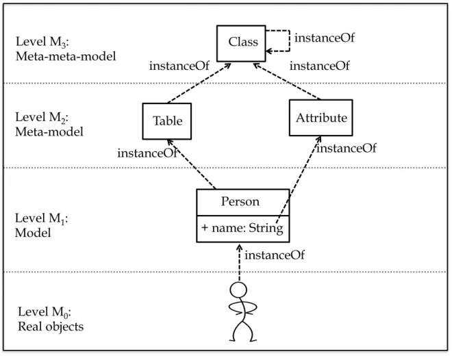
Figure 2.1 – Modeling in MDE
Figure 2.1 shows an example of modeling. Level M0 consists on the real objects (a
person). Level M1 contains the representation which describes the concept of Person with
its attribute name. The meta-model of this representation is shown at level M2. It describes
the concepts used in M1 (Table, Attribute). These concepts are in turn defined at level M3
which presents the meta-meta-model.
MDE gives models a predominating role in the software development process. Models are written in conformity with meta-models which capture the concepts of the modeling language. For example, the UML class diagrams define the concepts of class and attribute, the relational schema models define the concepts of table and column, etc.
Model Driven Architecture (MDA) [Soley and the OMG Staff Strategy Group, 2000] is the well known initiative of the OMG in this domain. It is sometimes viewed as a restric-tion of MDE to the languages introduced by the OMG. It also comes with a development methodology. Indeed, MDA advocates the construction of three models of a system:
20 Chapter 2. State Of The Art
the CIM. It presents what the system is expected to do. It hides all information related to the technology used for the system implementation.
2. Platform Independent Model (PIM): The goal of the design phase is to produce the PIM. It presents the operational view of the system independently from the platform. It defines a set of services to abstract all technical details. A PIM can be mapped to one or more platforms.
3. Platform Specific Model (PSM): The goal of the implementation phase is to produce the PSM. It combines the PIM with the specific details of the platform.
In an MDE process, models play an important role. To ensure the productivity of those models, model transformation (MT) is considered as a central concept. It provides mechanism for automating the manipulation of models.
2.2
Model Transformation
In [Kleppe et al., 2003], the authors provide the following definitions of MT:
Definition 2.4: "A transformation is the automatic generation of a target model from a source model according to a transformation definition".
Definition 2.5: "A transformation definition is a set of transformation rules that together describe how a model in a source language can be transformed into a model in a target language".
Definition 2.6: "A transformation rule is a description of how one or more constructs in a source language can be transformed into one or more constructs in a target language".
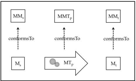
The basic idea of MT is presented inFigure 2.2where a model transformation program MTp takes as input a source model Msand produces a target model Mt. Being models, Ms
and Mtconform to meta-models MMsand MMs. MTpis composed of a set of rules which
have a complete knowledge about MMs and MMs. It has a meta-meta-model MMTp that
defines the used transformation language.
2.2.1 Model Transformation Classification
Mens and Gorp [Mens and Gorp, 2006] extend the definition of MT by allowing several models as input and/or output: "Model transformation is the automatic generation of one or multiple target models from one or multiple source models according to a
transforma-2.2. Model Transformation 21 Ms Mt MMt MMs MTp MMTp
conformsTo conformsTo conformsTo
Figure 2.2 – Model Transformation process
tion definition". They give the example of a transformation that takes a PIM and transforms it into a number of PSMs. They classify MTs according to different criteria:
• Exogenous versus endogenous transformations: We distinguish between two MT cat-egories: (1) exogenous transformations in which the source and target models are ex-pressed using different languages, and (2) endogenous transformations in which the source and target models are expressed in the same language. In exogenous transfor-mations, the entire source model elements must be transformed to their equivalents in the target model, e.g., the transformation of a relational schema (RS) model into an UML class diagram (CD). However, there are just a few endogenous transformations, e.g., for refactoring or improving performance of a code.
• Horizontal versus vertical transformations: An horizontal transformation is a trans-formation where the source and target models are at the same abstraction level. For instance, refactoring (endogenous transformation) is considered as an horizontal transformation. A refinement of models (endogenous transformation) is considered as a vertical transformation because the source and target models reside at different abstraction levels.
• Syntactical versus semantical transformations: A syntactical transformation trans-forms the syntax of the model, e.g., the transformation of a concrete syntax into an abstract syntax. A more complex transformation, such as a refactoring, is considered as a semantical transformation.
• Technical space: The technical space contains the concepts associated to a technology. It corresponds to the language used to present models. A technical space is
deter-22 Chapter 2. State Of The Art
mined in the meta-meta-model level. As an example, we note the MDA technical space defined by the OMG.
Several MT approaches have been proposed in the literature. Czarnecki and Helsen [Czarnecki and Helsen, 2006] classify these approaches as described in the following:
• Direct-Manipulation Approach: It offers an internal model and users can manipulate the representation using any Application Programming Interface (API). It is usually manipulated as an object-oriented framework, which may also provide some minimal infrastructures. Users must implement transformation rules, tracing and scheduling in a programming language such as Java or Visual basic (VB). Examples of used tools in direct manipulation approaches are: Rational Rose, Rational XDE and Builder Object Network.
• Operational Approach: This approach is similar to direct manipulation, but it offers more dedicated support for MT. A typical solution in this category is to extend the utilized meta-modeling formalism with facilities for expressing computations. An example would be to extend a query language such as OCL with imperative con-structs. Kermeta [Muller et al., 2005], QVT Operational mappings [OMG, 2002], MTL [Vojtisek and Jezequel, 2004] and XMF-mosaic [Clark et al., 2004] belong to the oper-ational category.
• Structural Approach: In this category of approaches, a first phase consists in creating a hierarchal structure for the target model. Then, the second phase generates target elements for each source element and sets the attributes and the references in the target model. OptimalJ is an example that supports this approach.
• Template-Based Approach: This approach uses template to generate code. A template consists of rules which are mapped on source model. Templates are expressed in the concrete syntax of the target model. They contain embedded metacode which have the form of annotations on model elements. In [Czarnecki, 2005], an example of template approach is given by Czarnecki and Antkiewicz. In this example, a template of an UML model is creating by using conditions and expressions to annotate model elements.
• Relational Approach: It is a declarative approach. It focuses on mathematical re-lations and on source and target models rere-lationships [Akehurst and Kent, 2002]. Relationships are specified using predicates and constraints. Operational approaches are bidirectional due to their mathematical foundation. They provide also backtrack-ing. Most of them require a strict separation between source and target models.
2.2. Model Transformation 23
Examples of relational approaches are ATL [Jouault et al., 2008] and QVT Relations [OMG, 2005].
• Graph-Transformation-Based Approach: This category is based on the theoretical work on graph transformations. The transformation rules consist of LHS (Left-Hand Side) and RHS (Right-Hand Side) graph patterns. The LHS pattern contains the pre-conditions of the rule and the RHS pattern represents the post-pre-conditions of the rule. The LHS pattern is matched in the model being transformed and replaced by the RHS pattern in place. LHST
RHS defines a graph part which must exist to apply the rule. Examples of graph-transformation-based approaches include VIATRA [Csertán et al., 2002], AGG [Taentzer, 2000] and GReAT [Agrawal et al., 2006] .
The difference between the two classifications is that Czarnecki and Helsen propose a hierar-chical classification based on feature diagrams. In addition, they classify the specification of MTs. By contrast, the classification of Mens and Gorp is essentially multi-dimensional. They propose a taxonomy more targeted towards tools and techniques which support the activity of MT.
2.2.2 Model Transformation Languages
Since the introduction of MDE [Schmidt, 2006] and MDA [Soley and the OMG Staff Strategy Group, 2000], two kinds of languages are proposed to write MT:
• General purpose languages, in which we can add libraries or frameworks to manip-ulate models. For example EMF [Frank, 2004] and Java.
• Specific Language that are dedicated to model transformations, such as:
ATL (Atlas Transformation Language) is a hybrid transformation language which supports declarative and imperative constructs. Thanks to its declarative style, ATL can simplify complex transformations algorithms. However, it is sometimes difficult to provide a complete declarative solution for complex transformation problem. In this case developers may resort to the imperative features of the language [Jouault et al., 2008].
Kermeta: is a meta-modeling, object-oriented and imperative programming lan-guage. It uses EMF tools to manipulate models. It offers constraints, checking and transformation. It does not support incremental model transformation.
QVT (Query/View/Transformation) is the OMG standard language for specifying MT. It uses the Object Constraint Language (OCL). QVT defines three transformation
24 Chapter 2. State Of The Art
languages [Biehl, 2010] : (1) QVT Relational which is a high-level declarative transfor-mation language which supports the specifications of bidirectional transfortransfor-mations, (2) QVT Core which is a low-level MT language which supports pattern matching and (3) QVT Operational which is an imperative MT language. The specified trans-formations are unidirectional.
GReAT(Graph Rewriting and Transformation) is a meta-model based MT language which uses meta-models to specify the abstract syntax of the source and the target models and the sequenced graph rewriting rules for specifying the transformation.
ETL (Epsilon Transformation Language) [Kolovos et al., 2008] is a hybrid and rule-based transformation language. It can transform many source to many target models. Thanks to its rule inheritance, rules can be reused and extended.
2.3
Towards Model Transformation Generation
The evolution of model transformation languages consists in increasing the abstraction level of languages. Although most of these languages are able to implement complex model transformation problems, they may be difficult to use for users who are not experts on spe-cific transformation languages. In addition, the solution domain of a model transformation (i.e., the transformation language) can be largely different from the problem domain (i.e., the source and the target model languages themselves) [Varró, 2006].
To address these challenges, several approaches are proposed to assist the specification and the design of MT.
2.3.1 Meta-model Matching for Model Transformation Generation
This approach is based on meta-models to generate MTs. Source and target models have to be similar, which is the case for example of model migration where the meta-models have two similar languages. This approach is inspired from the matching technique that is well known in the semantic web, schema, ontology and data warehouse domains [Rahm and Bernstein, 2001] [Shvaiko and Euzenat, 2005]. It takes as input a source schema and a target schema and generates a set of relations between them.
A first contribution proposed by [Lopes et al., 2005] [Lopes et al., 2006b] consists on defining an algorithm, called SAMT4MDE, that operates at the meta-model level to gener-ate an alignment between source and target meta-models. It assumes that source and target models are similar in their structure and their terminology. String values of attributes are
2.3. Towards Model Transformation Generation 25
used to find correspondences between source and target elements. Then they define a tool, called MT4MDE, that uses this alignment to generate MTs written in ATL.
In [Lopes et al., 2009], SAMT4MDE is improved by using the structure similarity of the elements to find the correspondences between models.
In [Del Fabro and Valduriez, 2007], a similar approach is proposed to semi-automate the production of MTs. A first phase consists on discovering the relationships between the source and target models to create a weaving model. This latter is obtained by measuring the similarity between the attributes values (of type String) of the input models’ elements. The similarity flooding algorithm [Melnik et al., 2002] is also used to construct the adequate propagation models that capture the semantics of the relationships. The weaving model is then refined by an expert.
The contribution of Falleri [Falleri et al., 2008] is inspired from the work of Del Fabro and Valduriez. They transform the source and target meta-models into directed labeled graphs. Those graphs are then exploited by the Similarity Flooding algorithm to compute the map-ping between the meta-models elements and generate an Ecore alignment model from which MT is derived. They study several configurations for applying Similarity Flooding algorithm in the context of meta-model alignment with the aim of determining the best configurations.
In [Kappel et al., 2006], the authors consider the mapping between two meta-models difficult because the meta-models represent an abstract syntax of the corresponding mod-eling language and a data structure for storing models. As a consequence, they do not make explicit certain language concepts. Thus, they propose to lift meta-models into on-tologies to make the implicit concepts in the meta-model explicit in the ontology. Then, COMA++, an ontology alignment technique, is applied to compute the mapping between the source and target ontologies. Finally, alignments on ontologies are brought back to the meta-models.
Meta-model alignment is especially relevant when the source and target meta-models are semantically and structurally closed, e.g. when the transformation aims at migrating models from one meta-model version to another, but is inefficient on complex cases. When it can be applied, meta-model alignment reduces significantly the time of the development. Other approaches (MTBE for Model Transformation Based Example) take advantage of transformation examples to learn transformations in more complex cases. One of their strengths is that transformation examples, written in the concrete syntax, are easier to
26 Chapter 2. State Of The Art
manipulate than meta-models and their creation can be deferred to domain experts who do not need any programming skill.
2.3.2 Model Transformation By Example
Model Transformation by example (MTBE) [Kappel et al., 2012] is a novel approach based on other by-example approaches like programming by example (pbE) [Lieberman, 1993], also known as programming by demonstration, which teaches a computer new
be-haviors by demonstrating actions or concrete examples.
Based on the by-example approaches, MTBE derives model transformation rules from a set of source and target models which describe the model transformation problem in a declarative way. The input models have to be established by the user. A matching between models is created to help the learning of rules. The advantage of this approach is that the concepts of the source and target models are used for the specification of the transformation.
2.3.2.1 MTBE approaches
The MTBE approach has been initiated by Varró [Varró, 2006]. An alignment between representative source and target example models is manually created. Transformation links are annotated by the transformation rule they illustrate (e.g. ClassToEntity). Transformation rules are derived from the transformation links and refined by the developer. Rules are validated on new source and target example models. If they are not satisfactory, the process iterates. The limitation of this approach is that it is not scalable for large industrial model transformation problems. In addition, it requires a manual intervention.
The proposal of [Varró, 2006] was extended in [Balogh and Varro, 2009], by using in-ductive logics programming (ILP [Muggleton and De Raedt, 1994]) to derive the trans-formation rules. ILP is a machine learning technique which derives a logic program from existing knowledge (source and target models), positive examples (pairs of model elements connected by transformation links) and negative examples (pairs of model elements that are not connected by transformation links). Considering only the immediate neighbors of each transformation-link end, the ILP engine infers an hypothesis for each transformation rule.
For the automation of this approach, a model transformation tool is implemented with an ILP engine. Small prototype mapping models are used to train the rules derivation.
2.3. Towards Model Transformation Generation 27
Wimmer et al. [Wimmer et al., 2007] propose a similar work which derive ATL trans-formation rules from examples. Both contributions use semantic correspondences between examples to derive rules. Examples are written in concrete syntax by taking advantage of the constraints explicitly applied by the transformation from the concrete syntax of a language to its abstract syntax. The main advantage of this solution is to be able to use the concrete syntax to define models and transformation links. However, model editors need to be written in a way that permits to extract constraints and to edit transformation links. This approach is applied on examples of business process models.
The work of Garcia-Magarino et al. [García-Magariño et al., 2009] is also considered as a variant of MTBE approaches. In their approach, the authors generate many-to-many transformation rules from meta-models which satisfy some developer constraints for the simulation of input patterns of several elements.
Another MTBE approach [Dolques et al., 2011; Dolques et al., 2009] uses an extension of the anchorPrompt approach [Noy and Musen, 2001] to assist the transformation link discovery, and Relational Concept Analysis (RCA) [Huchard et al., 2007] to derive com-monalities between the source and target meta-models, models and transformation links. Compared to the ILP-based proposal, the RCA-based approach does not use annotations on transformation links and proposes a set of transformation patterns organized in a lattice. Model Transformation By Demonstration (MTBD) [Langer et al., 2010; Sun et al., 2009;
Brosch et al., 2009], is a similar approach to MTBE. Through direct editing (e.g. add, delete, connect, update) of the source model, users are asked to demonstrate how the model trans-formation should be done. A recording engine was developed to capture user operations during a MT. The recorded fragments are then generalized to produce transformation pat-terns. However, this approach requires a high level of user intervention. The difference between the two cited works is that Sun et al. use the recorded fragments directly, however Langer et al. use differencing engine to generate ATL rules. In addition, the approach of Sun is applied to endogenous transformations while the approach of Langer is applied to both endogenous and exogenous ones.
Another track in MTBE consists in using the analogy to perform transformations using examples [Kessentini et al., 2008; Kessentini et al., 2009] [Kessentini et al., 2010a]. The pro-vided examples are manually decomposed into transformation blocks linking fragments of source models to fragments of target models. When a new source model has to be trans-formed, its constructs are compared to those in the example source fragments to select the similar ones. Blocks corresponding to the selected fragments, coming from
differ-28 Chapter 2. State Of The Art
Model transformation approaches Model Transformation
By metamodels matching By Example
[Lopes et al., 2005] ×
[Del Fabro and Valduriez, 2007] ×
[Falleri et al., 2008] ×
[Wimmer et al., 2007] ×
[Balogh and Varro, 2009] ×
[Kessentini et al., 2008] ×
[Dolques et al., 2010] ×
[Sun et al., 2009] ×
[Langer et al., 2010] ×
Our approach ×
Table 2.1 – Model Transformation approaches.
ent examples, are composed to propose a suitable transformation. Fragment selection and composition are performed through meta-heuristic algorithms. Thus, MT can be seen as an optimization problem where the transformation of a source model is obtained by finding, for each of its constructs, a similar transformation in the others examples. Particle Swarm Optimization (PSO) [Kennedy and Eberhart, 1995] and Simulated Annealing (SA) [ Kirk-patrick et al., 1983] heuristics are combined to automate MT . In [Kessentini et al., 2010a], the approach is applied to Sequence Diagrams to Colored Petri Nets transformation.
Compared to the above-mentioned approaches, the analogy-based MTBE does not pro-duce rules. This could be considered as a limitation if the goal is to infer reusable knowl-edge about transformations.
2.3.3 Synthesis
This section has introduced the existing work in the domain of generating model trans-formation. Table 2.1summarizes the proposed approaches to generate model transforma-tion. Diverse MTs have been identified and a number of techniques and tools have been developed to automate their generation and put them into practice. The context of our approach is model transformation by example (MTBE). The user has to create model trans-formation examples. An example consists of a source model and its corresponding model in the target language. Then several techniques can be used, such as relational concept analysis or inductive logic, to derive model transformation rules from the examples. These rules are abstract and not operational. They represent fragments of knowledge and must be arranged in a non-trivial way to perform the actual transformation. The approach of Kessentini consists in using search-based optimization techniques to directly generate the
2.4. Model Transformation Traceability 29
By_Example Approaches Exogenous
transforma-tion Endogenous transforma-tion Matching Rules generation Rules execution Techniques & Tools
[Wimmer et al., 2007] × × × ad hoc
method
[Kessentini et al., 2008] × × metaheuristic
methods
[Sun et al., 2009] × × recording
engine
[Balogh and Varro, 2009] × × × ILP
[Langer et al., 2010;Brosch et al., 2009] × × × × differencing
engine
[Dolques et al., 2011] × × × FCA, RCA
Our approach × × × × FCA, RCA,
JESS
Table 2.2 – Model transformation by Examples approaches.
target model from the source model without the rules generation. This could be considered as a limitation if the goal is to infer reusable knowledge about transformations. In this con-text, the generation of operational rules from the existing examples can be preferable since it allows those rules to be executed on other source models to directly obtain the target models. Table 2.2 summarizes the proposed MTBE approaches. Most of them are specific to exogenous transformation and use matching techniques to derive transformation rules. The approach we propose is based on the work of Dolques et al. that uses RCA and FCA as learning techniques to derive transformation patterns. Those patterns are not operational. Thus, we propose to use the rule engine Jess to facilitate their manipulation and execution.
2.4
Model Transformation Traceability
In model-driven engineering, there is a concern on tracing model transformations dur-ing a software development. Some model transformation tools provide an integrated sup-port for traceability such as QVT [OMG, 2005] and MOFScript [OMG, 2006]. With ATL [Bézivin et al., 2003], developers can encode a trace as an output model. In [Jouault, 2005], Jouault proposes to attach traceability generation code to ATL program. Grammel et Al. [Grammel and Kastenholz, 2010] propose a generic framework for augmenting arbitrary model transformation approaches with a traceability mechanism. This framework is based on a domain-specific language for traceability. In [Kurtev et al., 2007], the authors focus on generated trace relations as part of QVT transformations. In the same context, Amar et al. [Amar et al., 2010] present an approach to automatically trace imperative model transfor-mation in a Java/EMF environment. Finally, a recent work [van Amstel et al., 2012] consists