HAL Id: tel-01591494
https://tel.archives-ouvertes.fr/tel-01591494
Submitted on 21 Sep 2017HAL is a multi-disciplinary open access
archive for the deposit and dissemination of sci-entific research documents, whether they are pub-lished or not. The documents may come from teaching and research institutions in France or abroad, or from public or private research centers.
L’archive ouverte pluridisciplinaire HAL, est destinée au dépôt et à la diffusion de documents scientifiques de niveau recherche, publiés ou non, émanant des établissements d’enseignement et de recherche français ou étrangers, des laboratoires publics ou privés.
Btissam Er-Rahmadi
To cite this version:
Btissam Er-Rahmadi. Cooperation and self -* for small cells networks. Networking and Internet Architecture [cs.NI]. Université Rennes 1, 2016. English. �NNT : 2016REN1S060�. �tel-01591494�
THÈSE / UNIVERSITÉ DE RENNES 1
sous le sceau de l’Université Bretagne Loire
pour le grade de
DOCTEUR DE L’UNIVERSITÉ DE RENNES 1
Mention : Informatique
Ecole doctorale MATISSE
présentée par
Btissam Er-Rahmadi
Préparée à l’unité de recherche UMR6074 – IRISA
Institut de Recherche en Informatique et Systèmes Aléatoires
Equipes d’accueil : Orange Labs CMA/MAX (ex. CMA/BATS) -
IRISA/DIONYSOS
Convention CIFRE N 2012/1106
Cooperation and
Self-* for Small
Cells Networks
Thèse rapportée par :
Yacine GHAMRI-DOUDANE
Professeur, Université de la Rochelle/ rapporteur
Pascal LORENZ
Professeur, Université Haute-Alsace / rapporteur
et soutenue à Rennes
le 15 Septembre 2016
devant le jury composé de :Pascal LORENZ
Professeur, Université Haute-Alsace / rapporteur
Dominique GAITI
Professeur, Université de Troyes / examinatrice
Erwan LEMERRER
Ingénieur Senior, Technicolor / examinateur
Djamal-Eddine MEDDOUR
Ingénieur Senior, Orange Labs / membre-encadrant
Adlen KSENTINI
Maître de Conférence, Université de Rennes 1 /
directeur de thèse
César VIHO
Professeur, Université de Rennes 1 / co-directeur
THESIS / UNIVERSITY RENNES 1
under the seal of University Bretagne Loire
for the degree of
DOCTOR OF UNIVERSITY RENNES 1
Mention : Computer Science
Doctoral School MATISSE
presented by
Btissam Er-Rahmadi
Prepared at Research Unit UMR6074 – IRISA
Institut de Recherche en Informatique et Systèmes Aléatoires
Hosting teams: Orange Labs CMA/MAX (ex. CMA/BATS) -
IRISA/DIONYSOS
CIFRE Convention N 2012/1106
Cooperation and
Self-* for Small
Cells Networks
Thesis reported by:
Yacine GHAMRI-DOUDANE
Professor, University la Rochelle/ reporter
Pascal LORENZ
Professor, University Haute-Alsace / reporter
and defended in Rennes
15 September 2016
Jury committee:Pascal LORENZ
Professor, University Haute-Alsace / reporter
Dominique GAITI
Professor, University Troyes / examiner
Erwan LEMERRER
Senior Engineer, Technicolor / examiner
Djamal-Eddine MEDDOUR
Senior Engineer, Orange Labs / member-supervisor
Adlen KSENTINI
Associate Professor, University de Rennes 1 / thesis
director
César VIHO
Professor, University de Rennes 1 / thesis
mountain, a mother’s goodness deeper than
the sea."
Firstly, I would like to express my sincere gratitude to my advisors Dr. Djamal-Eddine Meddour and Dr. Adlen Ksentini. They gave me the chance to take a challenging experience in the Orange Labs. Their guidance and insights over the years have been invaluable to me. I feel especially fortunate for the patience that they have shown with me when I firstly stepped into research in mobile networks architectures. They had no hesitation to express their continuous support and en-thusiasm, and share their immense knowledge that have improved the quality of my work. It has been a great honor and pleasure for me to do research under their supervision.
Besides my advisors, I would like to thank the rest of my thesis committee: Pr. César Viho, Pr. Yacine Ghamri-Doudane, Pr. Pascal Lorenz, Pr. Dominique Gaiti and Dr. Erwan Lemerrer for serving as my Ph.D committee members and reviewing my dissertation.
This work was carried out at the Orange Labs, Lannion, France in collaboration with IRISA, Rennes, France.
I would like to thank the BATMEN, BATS team members, for their warm welcome. Even we did not get the chance to collaborate in a common work, I learned contin-uously amazing things each time I discussed with them. I am also grateful to all colleagues and friends in the Orange Labs, Lannion for their memorable time.
I would like to thank DIONYSOS team at IRISA for hosting me and easing my visit to the IRISA premises. My special thanks go to Dr. Osama Arouk: he always replied to my questions about anything related to the laboratory.
During my thesis, I get the chance to work with Dr. Miloud Bagaa. I owe thanks to him: he helped me to address technical and scientific problems.
I take this opportunity to express my profound gratitude to all my friends for their continued help and support. In the Lannion family, I thank especially Wafa, Ilham and Somia for their support and amazing presence in my life.
Finally, I owe the biggest thanks to my parents Fatima and Mohamed, my brothers Elyas and Anas and my aunties Mahjouba and Zahra for their unconditional love and support. They always provided me with support, encouragement and guidance, especially in hard moments. My thanks would never suffice their absolute generosity. I feel also grateful to all my family members.
The recent phenomenal traffic growth is driving mobile operators to tier their pricing plans based on consumed bandwidth. To maximize data traffic monetization, opera-tors will need to consider smarter approaches while upgrading their current networks or deploying new ones. Small Cells are an integral part of both mature 3G/4G and future 5G cellular networks. Small Cells may be de facto deployed in heterogeneous architectures for Macro cells densification, or homogeneously for minimum broad-band coverage. In this respect, emerging challenges must be tackled: a reliable and economical backhaul is vital for Small Cells deployments. It is specifically more constraining for Small Cells deployments in green-field areas, where transport in-frastructure are absent or non-owned. In other words, the mobile operator wants to ensure good quality access to broadband services based only on Small Cells, while reducing overall installation cost. In this thesis, we focus on cost-efficient backhaul solutions that may provide the minimum capacities required by end users.
Our first contribution targets the provisioning of 4G Small Cells networks with suf-ficient capacity. Firstly, we provide a cost-efsuf-ficient method that minimizes backhaul cost while respecting the constraints of access network traffic demand and connect-ing technologies characteristics. This method provides with customized cost-optimal backhaul solutions for a given Small Cells access network; those solutions are made up of different linking technologies. Secondly, we analyze the impact of end users activity -i.e. data exchange- on generated traffic on both a Small Cell logical inter-faces S1 and X2; by taking into account different traffic components of an end user device. The analysis supplies with valuable insights on selecting the needed backhaul solutions.
In our second contribution, we focus on improving capacity in WLAN systems. We design a MAC scheduling scheme for uplink multi-users transmissions: it enables to exchange minimal control frames required for the establishment of transmissions
between the multiple transmitters and the receiver. Both analytic results and con-ducted proof-of-concept simulations show improved efficiency for both system and user oriented performances.
Keywords: Small Cells, Green-Field Deployments, Wireless Backhaul, WLAN High capacity, UL MU-MIMO.
La croissance phénoménale du trafic pousse les opérateurs mobiles à différencier leurs plans de tarification en se basant sur la bande passante consommée. Afin de maximiser la monétisation du trafic de données, les opérateurs devront envisager des approches plus intelligentes tout en améliorant leurs réseaux actuels ou en dé-ployant de nouvelles infrastructures. Les Small Cells sont une partie intégrante des réseaux cellulaires matures 3G/4G et futurs 5G. Les Small Cells peuvent être de facto déployées dans des architectures hétérogènes pour la densification des réseaux macrocellulaires, ou de façon homogène pour une couverture en haut débit. Pour le deuxième case de déploiement, de nouveaux défis doivent être résolus: un réseau de collecte fiable et économique est vital pour les déploiements des Small Cells. Le réseau de collecte est spécifiquement plus contraignant pour les déploiements des Small Cells dans les zones dites green-field, où les infrastructures de transport sont absentes ou présentes mais ne peuvent être contrôlées par l’opérateur. En d’autres termes, l’opérateur mobile souhaite garantir une bonne qualité d’accès aux services haut débit en se basant uniquement sur des Small Cells, tout en réduisant le coût global de l’installation. Dans cette thèse, nous nous focalisons sur des solutions de réseau de collecte rentables qui peuvent fournir les capacités minimales requises par les utilisateurs finaux.
Notre première contribution vise à assurer une capacité suffisante aux réseaux Small Cells 4G. Tout d’abord, nous proposons une méthode rentable qui minimise les coûts du réseau de collecte tout en respectant les contraintes de : 1) demande de trafic dans le réseau d’accès, et de 2) caractéristiques technologiques des liens de collecte. Cette méthode permet d’obtenir des solutions sur mesure de réseau de collecte à coûts optimal pour un réseau d’accès donné, basé sur des Small Cells; ces solutions sont constituées de différentes technologies de liaison. Deuxièmement, nous analysons l’impact de l’activité des utilisateurs finaux sur le trafic généré à la fois sur les deux
interfaces logiques S1 et X2 d’une Small Cell, tout en tenant compte les différentes composantes de trafic moyen d’un utilisateur final. Cette analyse permet d’avoir un aperçu très utile pour la sélection des solutions nécessaires au réseau de collecte.
Dans notre deuxième contribution, nous nous focalisons sur l’amélioration des ca-pacités des systèmes WLAN. Nous concevons un protocole d’ordonnancement MAC pour les transmissions uplink multi-utilisateurs: il permet un échange minimal des trames de contrôle requises pour la mise en place des transmissions entre les multi-ples émetteurs et le récepteur. Les résultats d’analyse et de simulations révèlent des performances améliorées, d’un point de vue du système et de l’utilisateur.
Mots-clefs: Small Cells, Dépoilements Green-Field, Réseau de Collecte Sans Fil, WLAN Haute capacité, UL MU-MIMO.
0.1
Introduction
Les small cells ont vu le jour dans le contexte de la densification des réseaux, prin-cipalement dans les zones urbaines. En fait, une estimation récente indique que le trafic de données mobiles a augmenté de 74%1 durant l’année 2015 et prévoit une augmentation annuelle de 53%2de 2015 à 2020. Cette demande accrue est due à dif-férents facteurs. Premièrement, les équipements sans fil sophistiqués des utilisateurs finaux sont améliorés en permanence pour prendre en charge de nouvelles fonction-nalités. Deuxièmement, des applications gourmandes en bande passante avec des contenus riches se développent constamment. En troisième lieu, le revenu moyen par utilisateur croit à des vitesses différentes selon les zones géographiques; cela favorise une grande pénétration des smartphones.
Dans ce contexte, les opérateurs de réseaux mobiles devront fournir plus de capac-ités afin d’assurer à leurs abonnés les vitesses qu’ils exigent. La densification du réseau sert à cet effet. La technologie des small cells est l’un des principaux moyens qui permettent d’améliorer la capacité dans un réseau. Les small cells sont utilisées conjointement avec des macrocellules pour fournir la couverture/capacité, avec la possibilité de handoff entre les deux technologies. Les small cells sont des solutions avantageuses quant à l’accroissement de la capacité du réseau, elles peuvent égale-ment servir de camouflage pour les ’trous’ de couverture des macrocellules; tout cela grâce à leur transposition en version miniaturée des macrocellules.
En effet, le terme générique "Small Cells" désigne les noeuds d’accès radio à faible puissance, contrôlés par l’opérateur, y compris les noeuds opérant dans un spectre
1
Source: Cisco VNI Mobile, 2016
2Source: Cisco VNI Mobile, 2016
sous licence et la Wi-Fi sans licence3. En la comparant à une macrocellule typique dont la couverture peut atteindre quelques dizaines de kilomètres, la couverture d’une small cell varie entre des dizaines à quelques milliers de mètres. Typiquement, une Femtocell peut émettre un signal radio à une puissance maximale de 23dBm; ce signal peut atteindre jusqu’à 50m de portée. La puissance de transmission d’une Picocell varie entre 23 et 30dBm, son rayon de couverture est compris entre 200-300m. Une Microcell a une portée de couverture plus importante: jusqu’à 2km; elle a une puissance de transmission de 30-46dBm. La portée d’un point d’accès Wi-Fi dépend de la technologie, mais ne dépasse pas 250m. Il transmet les signaux sans fil aux alentours de 25dBm.
La compacité des small cells a plusieurs avantages. Tout d’abord, les small cells per-mettent d’assurer une couverture meilleure. Les Microcells sont basiquement conçues pour étendre la couverture au profit des utilisateurs indoor/outdoor, là où la couver-ture d’une macrocellule est insuffisante. En outre, les Femtocells déployées conjointe-ment avec des macrocellules permettent d’améliorer la couverture, particulièreconjointe-ment dans les déploiements moins denses. En fait, l’opérateur mobile japonais Softbank a réussi à déployer des Femtocells pour couvrir des villages et des localités isolées, et ce en utilisant une ingénierie spécifique à l’outdoor. Les small cells ont besoin de moins de puissance : puisque les small cells utilisent des stations de base plus petites, elles nécessitent moins de ressources énergétiques, que cela soit pour la transmission du signal radio ou la consommation de l’équipement. Les déploiements denses des small cells promettent de réduire significativement la consommation d’énergie. Lorsque les small cells sont utilisées en mode veille, l’impact sur l’efficacité énérgitique du réseau d’accès radio (RAN) est proéminent. Les small cells génèrent moins de coûts. En ef-fet, les besoins énergétiques faibles sont traduits automatiquement par des économies de coûts. De plus, les équipements de small cells coûtent beaucoup moins cher, ce qui permet de réaliser d’importantes économies. Finalement, les small cells sont faciles à déployer, puisqu’elles sont commercialisées dans des boitiers de taille moyenne à petite, et qu’elles n’occupent pas beaucoup d’espace.
0.2
Problématique de la thèse
Les avantages potentiels qu’offrent les small cells ont poussé certains opérateurs de réseaux mobiles à les considérer comme alternative de couverture dans les zones où
l’opérateur ne possède ou ne peut contrôler les infrastructures de transport. En effet, les small cells peuvent être déployées seules dans des régions où aucune infrastructure d’accès n’est accessible pour assurer une connectivité au haut débit de l’opérateur. Cependant, le coût du déploiement de nouvelles infrastructures de transport est élevé comparé aux revenus de la population. D’un point de vue économique, il n’est plus avantageux de servir ce genre de populations. Le business plan du réseau de collecte ne doit pas être un obstacle au déploiement des small cells dans ces zones.
Dans ce contexte, les technologies sans fil (comme micro-ondes, satellite ou Wi-Fi) sont des solutions stratégiques pour réduire les coûts des réseaux de transport et ainsi, faciliter le déploiement des small cells. Comparées aux technologies filaires (comme la fibre ou le câble coaxial), les infrastructures sans fil du réseau de collecte ont quelques limitations : l’une des plus cruciales est un faible débit. Le réseau de collecte des small cells doit être en mesure de transporter le trafic des utilisateurs finaux sans sacrifier les performances du réseau.
Dans cette thèse, nous abordons les défis des réseaux de collecte sans fil des small cells, destinées à couvrir des zones où aucune infrastructure filaire de l’opérateur n’est disponible. Pour cela, nous visons à satisfaire les besoins des zones de service en termes de capacité, tout en gardant à l’esprit les règles de déploiement et les contraintes économiques de l’opérateur.
0.3
Contributions de la thèse
Le déploiement des small cells dans les zones non-couvertes est fortement associé à la fourniture de services internet avec une qualité de service minimale, tout en générant des coûts plus faibles et moins de complexité de dépoilements. Même si les small cells sont des solutions à faible coût et faciles à déployer, leur réseau de collecte doit également être rentable tout en assurant une connectivité de bonne qualité. Le choix des solutions de collecte les plus adaptées est dicté par les exigences des utilisateurs finaux en termes de débit, dans le temps et l’espace. Le réseau de collecte peut être composé de différentes solutions pour le même RAN: le Wi-Fi est une solution prometteuse, spécialement pour les small cells des WLAN. Le Wi-Fi permettrait d’atteindre de grandes capacités lorsque certaines technologies évoluées y sont incluses: la technique uplink multi-utilisateurs MIMO (UL MU-MIMO) est un facteur clé pour l’amélioration des capacités des systèmes WLAN et des utilisateurs
en uplink.
Cette thèse est composée de deux parties. Dans la première partie, nous analysons les caractéristiques du réseau de collecte des small cells, ensuite nous proposons deux approches pour améliorer le dimensionnement de la collecte par rapport à la demande de trafic des utilisateurs finaux.
La première approche vise à choisir des solutions de collecte tout en respectant certaines contraintes:
• Planification optimale des réseaux small cells en fonction du coût dans les zones sans infrastructures : nous ciblons le problème du choix des solutions de collecte les plus appropriées, y compris les types de technologies et les nœuds agrégateurs, qui génèrent le coût d’installation le plus minimaliste. Nous considérons un ensemble de small cells destinées à desservir une zone spécifique. Les emplacements des small cells sont prédéfinis par la planification radio. Nous proposons ensuite un modèle d’optimisation de coût exprimé sous forme d’un problème d’optimisation. Ce problème vise à minimiser le coût des connexions de collecte tout en respectant les contraintes des caractéristiques des technologies et du trafic du réseau. Un accès réseau small cells peut être relié de différentes façons selon les technologies définies par la stratégie de l’opérateur, et peut donc avoir différentes solutions de collecte.
Dans un deuxième temps, nous évaluons l’impact de l’activité des équipements d’utilisateurs finaux sur le trafic acheminé par les interfaces logiques d’une small cell:
• Planification de réseaux small cells basée sur une analyse de trafic : le besoin en débit d’une zone de service indique la capacité des technolo-gies de collecte sélectionnées. En fait, ce besoin devrait être quantifié afin de pouvoir déployer les small cells d’une manière efficace et scalable. Cette quan-tification permettrait d’évaluer la quantité de trafic acheminée depuis le réseau coeur à l’utilisateur final via la small cell en accès, et vice versa. Pour cette raison, nous analysons le trafic acheminé par un segment de collecte des small cells. En effet, nous divisons la pipeline de la collecte en plusieurs composantes selon deux critères : 1) leur acheminement via l’interface S1 ou X2, et 2) le type d’information qu’elles acheminent: paquets de signalisation ou de données d’utilisateurs. En utilisant les mêmes critères, nous partageons le débit moyen d’un utilisateur en différents pourcentages de participation. Nous modélisons
ainsi le comportement du trafic généré sur les deux interfaces logiques (S1 et X2) d’une small cell en utilisant une chaîne de Markov. Ce modèle prend en considération l’effet qu’a l’activité des utilisateurs finaux sur les interfaces de connexion de la small cell.
La deuxième partie de cette thèse est dédiée à la conception, l’évaluation analytique et la mise en œuvre d’un protocole d’ordonnancement des transmissions UL MU-MIMO en WLAN.
• Amélioration de la capacité des systèmes Uplink multi-utilisateurs MIMO : en tant que solution de collecte sans fil très attractive pour tout type de technologie small cell (qu’elle soit cellulaire ou basée sur dans les WLAN), les liens Wi-Fi devront supporter des performances symétriques ulpink/downlink en débit. Des techniques supplémentaires, comme les transmissions multi-utilisateurs, peuvent être incluses dans les systèmes WLAN afin d’atteindre la capacité souhaitée. Dans cette perspective, nous identifions et analysons les problèmes techniques de multi-utilisateurs MIMO en uplink. Nous proposons ensuite un nouveau protocole d’ordonnancement de la couche MAC dont le but est de réduire les messages de contrôle générés par les multiples émetteurs et le récepteur afin d’établir cette transmission. Nous établissons deux versions de ce protocole: basique et améliorée. Par la suite, nous modélisons la version basique en utilisant un modèle semi-Markov afin d’évaluer les performances du système. Enfin, nous effectuons plusieurs simulations pour vérifier la haute efficacité apportée par le protocole uplink MU-MIMO.
0.4
Conclusion
Dans cette thèse, nous avons traité les problématiques d’accès aux services haut débit en se basant uniquement sur des small cells, dans des zones sans infrastructures de l’opérateur. Plus précisément, nous avons effectué une analyse, modélisations et op-timisation des réseaux d’accès et de collecte des small cells. Le but est d’assurer l’accès aux services haut débit avec une qualité de service satisfaisante tout en gar-dant à l’esprit l’aspect crucial des coûts encourus par les déploiements des small cells. Initialement, nous avons détaillé le contexte général de ce travail, à savoir les réseaux small cells; ensuite nous avons abordé les problématiques suivantes.
cells. Ce RAN a au moins un accès à un noeud agrégateur de service appartenant à l’opérateur. Nous avons proposé un modèle qui minimise les coûts engagés dans le réseau de collecte tout en respectant trois contraintes principales : les capacités des liens, la portée de la technologie utilisée et l’unicité du noeud agrégateur. Les résultats de calcul ont confirmé que les technologies sans fil sont plus rentables que les filaires. Ces résultats ont permis aussi d’obtenir des solutions hybrides pour un réseau de collecte sans fil.
Ensuite, nous avons effectué une analyse pour évaluer l’influence de l’activité des UEs sur le trafic des connexions logiques d’une small cell. En fait, les solutions sans fil utilisées dans le réseau de collecte dépendent des besoins de la zone à servir en termes de trafic; celui-ci est directement lié à la quantité de données échangées entre les équipements des utilisateurs finaux et le réseau de l’opérateur. Nous avons fournis également une classification du trafic d’un UE selon l’interface logique par laquelle il est acheminé (S1 ou X2) ou son type (plan de contrôle ou de données).
Enfin, nous nous sommes concentrés sur l’amélioration de la capacité des systèmes WLAN en uplink. Les techniques uplink MU-MIMO ne sont pas encore normalisées par aucun organisme de normalisation WLAN, bien qu’elles soient des alternatives propices à l’amélioration de la capacité. Nous avons proposé un protocole MAC qui permet d’ordonnancer une transmission uplink MU-MIMO tout en restant rétro-compatible avec les normes IEEE 802.11 actuelles; i.e. échanger le moins de trames de contrôle entre les multiples émetteurs et le récepteur. Nous avons évalué la perfor-mance système de ce protocole en utilisant un modèle semi-Markovien. Finalement, nous avons proposé une version améliorée qui permet de réduire d’avantages les over-heads, et avons vérifié ensuite l’efficacité des deux versions par des simulations.
Acknowledgments i
Abstract iii
Résumé v
Résumé Français vii
0.1 Introduction . . . vii
0.2 Problématique de la thèse . . . viii
0.3 Contributions de la thèse . . . ix
0.4 Conclusion . . . xi
Contents xiii List of Figures xvii List of Tables xix Abbreviations xxi Introduction 1 1 Small Cells Networks: Technological Glimpse 7 1.1 Introduction . . . 9
1.2 Legacy Architectures . . . 9
1.2.1 3GPP: 3G/4G . . . 9
1.2.2 Operator WLAN . . . 13
1.3 Small Cells Wireless Backhaul Requirements . . . 18
1.3.1 Connectivity . . . 19
1.3.2 Throughput/Capacity . . . 19
1.3.3 Delay . . . 20
1.3.4 Security . . . 21
1.3.5 Synchronization . . . 22
1.3.6 Low Installation Cost . . . 23
1.4 Wireless backhaul links . . . 25
1.4.1 Millimeter wave . . . 25 1.4.2 Microwave . . . 26 1.4.3 Wi-Fi . . . 27 1.4.4 Satellite . . . 27 1.4.5 TV white spaces . . . 28 1.4.6 Comparative Summary . . . 28
1.5 UL MU-MIMO transmissions for enhanced Wi-Fi capacity . . . 29
1.5.1 MU-MIMO transmissions . . . 30
1.5.2 Challenges of UL-MU in WLAN . . . 32
1.6 Conclusion . . . 33
2 Cost-Optimal Planning in a Green-Field Small Cells Network 35 2.1 Introduction . . . 36
2.2 Cost Optimal backhaul for data aggregation . . . 36
2.2.1 Model description . . . 37
2.2.2 Performance Analysis . . . 41
2.2.2.1 Evaluation method . . . 41
2.2.2.2 Simulation results . . . 42
2.3 Use cases study . . . 48
2.3.1 Considered topologies . . . 48
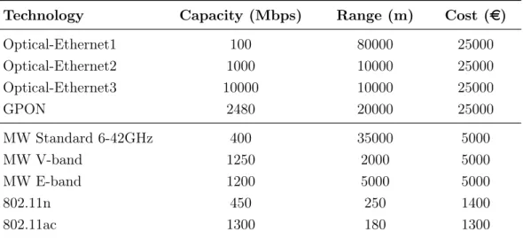
2.3.2 Greedy heuristic algorithm . . . 49
2.3.3 Results comparison . . . 50
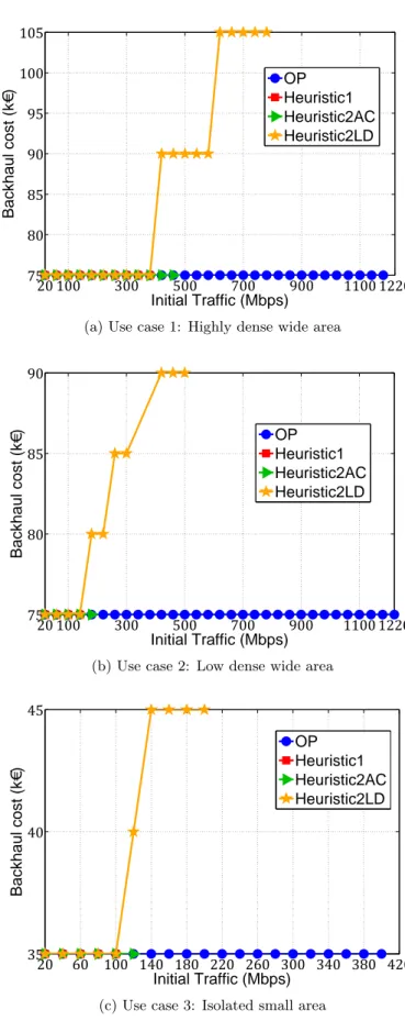
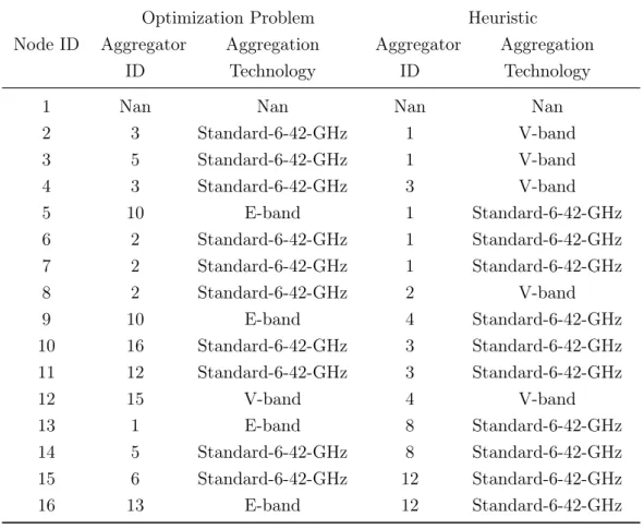
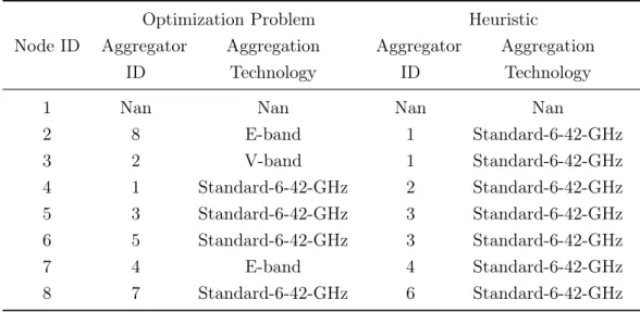
2.3.3.1 Backhaul costs comparison . . . 52
2.3.3.2 Backhaul solutions . . . 53
2.3.4 Summary . . . 53
2.4 Practical aspects discussion . . . 58
2.5 Conclusion . . . 60
3 Small Cells Network Planning based on Traffic Analysis 61 3.1 Introduction . . . 62
3.2.1 General description . . . 63 3.2.2 Proposed approach . . . 64 3.3 Backhaul pipline traffic analysis . . . 66 3.3.1 Backhaul traffic: Small Cell perspective . . . 66 3.3.2 Backhaul traffic: End user perspective . . . 67 3.4 Model description . . . 71 3.4.1 Bi-dimensional Markov Chain . . . 71 3.4.2 Average Throughput on interfaces S1 and X2 . . . 75 3.5 Evaluation . . . 76 3.5.1 S1/X2 throughput . . . 77 3.5.2 Blocking Probability . . . 80 3.5.3 Overheads Consideration . . . 82 3.6 Conclusion . . . 82
4 On enhancing Uplink Multi-Users MIMO transmissions 85
4.1 Introduction . . . 86 4.2 Design of the UL MU-MIMO scheduling scheme . . . 87 4.2.1 Wait-to-Pick-As-Available: W2PAA . . . 87 4.2.2 Enhanced W2PAA: W2PAA-E . . . 88 4.3 Analytical Model of W2PAA . . . 90 4.3.1 System Modeling . . . 90 4.3.2 Model discussion . . . 93 4.4 Simulated W2PAA and W2PAA-Enhanced . . . 95 4.4.1 General Assumptions . . . 95 4.4.2 Performance evaluation metrics . . . 96 4.4.3 Simulations results discussions . . . 98 4.4.3.1 Impact of Network size . . . 98 4.4.3.2 Impact of Channel bandwidth . . . 107 4.4.3.3 Impact of Modulation and Coding Scheme . . . 110 4.5 Conclusion . . . 116
Conclusion and Perspectives 117
A Performance measures computing 123
A.1 Transmission Probability . . . 123 A.2 Holding time components . . . 125 A.3 Throughput . . . 127
A.4 Average Delay . . . 128
Publications 129
1.1 3GPP Small Cells Architecture . . . 12 1.2 Aggregated Cellular Small Cells Architecture . . . 13 1.3 A simplified Operator WLAN architecture . . . 18 1.4 Mobile Backhaul TCO components [49] . . . 24 1.5 Comparison across scenarios of cumulative CAPEX and OPEX per
Mbps after 5 years. (Source: Senza Fili Consulting) [55] . . . 25
2.1 A sixteen SCs network with three root nodes: (a) Initial network not linked, dashed lines are possible aggregations (b) A solution of linking SC nodes to the core network using two different technologies (blue and red arrows pointing to chosen aggregators) . . . 38 2.2 Generated costs versus surface areas (km2) . . . 44 2.3 Generated cost versus initial traffic for each node (Mbps) . . . 45 2.4 Generated cost versus percentage of root nodes . . . 46 2.5 Mixed Backhaul characteristics versus Initial Traffic (Mbps) . . . 47 2.6 Considered Access Small Cells based Network topologies . . . 49 2.7 Heuristic 1 Flow Chart . . . 51 2.8 Generated Backhaul costs versus the initial traffic for the three
topolo-gies . . . 55 2.9 Optimal solution computational complexity measurements . . . 59
3.1 The logical architecture of the LTE access network . . . 67 3.2 UE Traffic components . . . 70 3.3 Bi-dimensional Markov chain diagram . . . 73 3.4 Generated traffic on logical interfaces versus N . . . 78 3.5 Generated traffic on logical interfaces versus p . . . 78 3.6 Generated traffic on logical interfaces versus TU E . . . 79
3.7 Generated traffic flows shares on interfaces S1 and X2 versus p . . . 80 3.8 Blocking probability versus p . . . 81 3.9 Blocking probability versus TU E . . . 81 3.10 Overheads shares of Generated traffic flows on interfaces S1 and X2
versus p . . . 82
4.1 Example of WP2AA transmission protocol: two out of three contend-ing scontend-ingle antenna stations win the UL MU TXOP to an AP with four antennas. . . 88 4.2 Semi-Markov Chain . . . 92 4.3 Analytic System Throughput versus number of contending stations . 94 4.4 Analytic Average Delay versus number of contending stations . . . . 95 4.5 Probability of successful transmission versus number of contending
stations . . . 95 4.6 Per-STA Throughput as a function of number of contending stations 100 4.7 Per-STA Throughput gains . . . 100 4.8 CDF of per-STA Throughput . . . 102 4.9 Average Delay as a function of number of contending stations . . . . 103 4.10 Average Delay gain . . . 103 4.11 System Throughput as a function of number of contending stations . 104 4.12 Transmission Latency as a function of number of contending stations 105 4.13 Re-Transmission Ratio vs. the number of contending stations . . . . 106 4.14 Fairness Index against number of contending stations . . . 107 4.15 Normalized Per-STA Throughput versus Channel Bandwidth . . . . 108 4.16 Normalized System Throughput versus Channel Bandwidth . . . 109 4.17 Average Delay versus Channel Bandwidth . . . 111 4.18 Normalized Per-STA Throughput versus MCS Index . . . 112 4.19 Normalized System Throughput versus MCS Index . . . 113 4.20 Average Delay versus MCS Index . . . 115
1.1 Specifications of 3GPP LTE Small Cells Architectures Variants . . . 14 1.2 Advantages of 3GPP LTE Small Cells Architectures Variants . . . . 15 1.3 Limitations of 3GPP LTE Small Cells Architectures Variants . . . . 16 1.4 Applicability of 3GPP LTE Small Cells Architectures Variants . . . . 17 1.5 Comparative overview of small cells wireless backhaul solutions . . . 29
2.1 Notations used in formulating the optimization problem. . . 39 2.2 Linking Technologies Characteristics. . . 42 2.3 Characteristics of considered use cases topologies . . . 52 2.4 Topology Aggregation solution using OP and Heuristic for highly
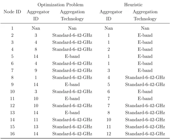
dense wide area (Initial Traffic = 400 Mbps) . . . 54 2.5 Topology Aggregation solution using OP and Heuristic for low dense
wide area (Initial Traffic = 150 Mbps) . . . 56 2.6 Topology Aggregation solution using OP and Heuristic for isolated
small area (Initial Traffic = 100 Mbps) . . . 57
3.1 Transport Overhead ratio for Control and User planes . . . 70 3.2 Default parameters . . . 76
4.1 Simulations parameters . . . 114 4.2 Significant Percentiles of Per-STA Throughputs (Mbps) . . . 115
A
AAA Authentication, Authorization, and Accounting
ACK Acknowledgment
aGW Aggregation Gateway
AP Access Point
B
BO Backoff
BS Base Station
BSS Basic Service Set
C
CAPEX Capital Expenditure
CDF Cumulative Distribution Function
CN Core Network
CoMP Coordinated Multipoint
CTS Clear To Send
D
DCF Distributed Coordination Function
DL Downlink
DIFS DCF Inter-Frame Space
DoS Denial of Service
DTV Digital TV
E
EAP Extensible Authentication Protocol
eICIC enhanced Inter-cell interference coordination
EIFS Extended Inter-Frame Space
EPC Evolved Packet Core
H
HOL Head Of Line
G
GNSS Global Navigation Satellite Systems
GPRS General Packet Radio Service
GTP GPRS Tunnelling Protocol
L
LOS Line-of-Sight
M
MAC Media Access Control
MC Macro Cell
MIP Mobile IP
MME Mobility Management Entity
mmWave Millimeter Wave
MPR Multi-Packet Reception
MU Multi-Users
MW Microwave
N
nLOS Near Line-of-Sight
NLOS Non Line-of-Sight
NTP Network Time Protocol
P
PHY Physical
PMIP Proxy Mobile IPv6
PoC Point of Concentration
PoP Point of Presence
ppb parts per billion
PS Packet Switched
PtMP Point-to-Multipoint
Q
QCI QoS Class Identifier
QoE Quality of Experience
QoS Quality of Service
QPEX Operating Expenditure
R
RAN Radio Access Network
RTS Request To Send
RTT Round Trip Time
S
SC Small Cell
SCF Small Cell Forum
SC-GW Small Cell Gateway
SCTP Stream Control Transmission Protocol
S-GW Serving Gateway
SIFS Short Inter-Frame Space
SIPTO Selective IP Traffic Offload
STA Station
SU Single-User
SyncE Synchronous Ethernet
T
TCO Total Cost of Ownership
TDD Time Division Duplex
TGax Task Group ax
TV Television
TVWS TV White Space
TXOP Transmission Opportunity
U
UDP User Datagram Protocol
UE User Equipment
UHF Ultra High Frequency
W
VHF Very High Frequency
W
WP2AA Wait-to-Pick-As-Available
WP2AA-E Wait-to-Pick-As-Available Enhanced
WAG WLAN Access Gateway
The early days of Small Cells Networks
The raison d’etre of small cells is to propose new alternatives to network densification, predominantly in urban areas. Actually, one recent estimation states that global mobile data traffic grew 74%4 in 2015 and is foretasted to grow annually at a rate of 53%5from 2015 to 2020. This ever growing thirst for mobile/wireless data is triggered by different elements. First, sophisticated wireless end users devices are constantly developed to support new features. Second, bandwidth-hungry applications with rich contents are continuously proliferating. Third, Average Revenue Per User (ARPU) is growing, although at different paces depending on world regions; this is favoring high smartphone penetration.
In this context, Mobile Networks Operators (MNOs) need to add more capacity to continue providing their subscribers with the speeds they demand. This is what network densification is meant for. Small cells are one of the key ways to improve system capacity. Small cells are employed together with macrocells to provide cover-age/capacity with eventual handoff capabilities. Small cells are attractive solutions towards increasing the network capacity and even fitting macrocells coverage ’holes’, thanks to their "smaller" reincarnation of macrocells.
As a matter of fact, the umbrella term "Small Cells" refers to operator-controlled, low-powered radio access nodes, including those that operate in licensed spectrum and unlicensed carrier-grade Wi-Fi 6. Compared to a typical macrocell whose coverage is up to several tens of kilometers, a small cell coverage ranges from dozen to few thousands meters. Typically, a Femtocell may transmit radio signals at a maximum
4Source: Cisco VNI Mobile, 2016 5
Source: Cisco VNI Mobile, 2016
6Source: Small Cell Forum
power of 23dBm, which can reach up to 50m. A Picocell signal transmit power is 23-30 dBm, and its coverage is up to 200-300m. A Microcell has wider coverage radius: up to 2km; it has a transmit power of 30-46dBm. Wi-Fi access point range depends on technology, but does not exceed 250m. It transmits at about 25dBm.
The smallness character of small cells provide this technology with attractive features. Firstly, they enable providing better coverage. Micro cells are basically designed to extend coverage for indoor/outdoor users where macro coverage is insufficient . Furthermore, Femto cells in Macro-joint deployment enable to improve coverage, especially in less dense deployment scenarios. Actually, the Japanese mobile oper-ator Softbank had a success story in deploying Femto cells with specific outdoor engineering design in order to cover isolated villages and localities. Small cells have lower power requirements: as small cells are based on small sized base stations, they require less energy resources either for signal transmission or equipment consump-tion. Dense deployments of small cells are promoting significant energy consumption reduction. When used with sleep mode, they have an observable impact on Radio Access Network (RAN) energy efficiency. Small cells have lower costs. Indeed, lower energy requirements are automatically interpreted as costs savings. Moreover, small cells equipment costs much less, which enables to achieve profitable cost savings. Finally, small cells are easy to deploy since they come in medium to small boxes, easy to replace and connect, and do not require large spaces.
Why should we care and what can we do?
Inspired by the potential advantages of small cells networks, some MNOs are seri-ously envisioning small cells as an alternative solution for covering areas where the operator does not own or control transport infrastructure. In fact, small cells might be deployed as the the only access nodes, in spaces where no access infrastructure is settled to ensure MNO broadband connectivity. However, the cost of deploying transport infrastructure is high in comparison with the population revenue. It is no more economically beneficial to serve such populations. Backhaul business plan should not be a barrier to small cell deployment in green-field areas.
In this respect, wireless technologies (like Microwave, Satellite or Wi-Fi) are strate-gic solutions to reduce transport networks’ costs and hence facilitate small cells deployments. There are some limitations affecting wireless backhaul infrastructure
compared to wired ones (such as Fiber or cable); one of the most crucial is low data rates. The small cells backhaul must be able to transport end users traffic flows without sacrificing network performance.
In this thesis, we address some of small cells wireless bakchaul challenges, intended to cover green-field areas where no operator wired infrastructure is available. For this purpose, we focus on respecting service areas demands in terms of capacity, while keeping in mind the deployments and economic constraints.
In the first instance, we deal with small cells backhauling with minimal required links capacities and aggregators, in such a way that incurred cost is the lowest possible. Since wireless technologies provide different capabilities like links capacity and range, their cost vary as well. We want to provide the most suitable backhaul configuration that respects most, if not all those parameters. Then, we deal with the influence of end users traffic on carried traffic by a single small cell interfaces. End users devices dictate the required bandwitdh in the backhaul segment.
In a second phase, we concentrate on enhancing WLAN cpacity performance. This is because Wi-Fi has a double role in future small cells: in the one hand, Wi-Fi links are one of the most cost-efficient solutions for backhauling; on the other hand, small cells technologies cover also small-size low-range wireless access nodes based on IEEE 802.11 standards. Wi-Fi systems should support symmetrical performance on both downlink and uplink directions. Nonetheless, the system capacity in uplink transmissions is not yet developed enough to reach downlink levels.
Contributions
Deploying small cells in uncovered areas is strongly associated to delivering minimum QoS services at lower cost and deployments complexity. Even though small cells solutions are low cost/easy to deploy radio access nodes, their backhaul should be also cost-effective while providing good quality connectivity. The choice of the most suitable wireless backhaul solutions is driven by end user requirements by respect to throughput over space and time. The backhaul may include different solutions for the same RAN: Wi-Fi is a promising one, especially for WLAN small cells. The latter may reach high capacity when some advanced techniques are implemented: UL MU-MIMO is a key enabler for WLAN system and user uplink capacities.
back-haul proprieties, then we propose two approaches to improve backback-haul dimensioning regarding required end users traffic demand.
The first approach aims at making backhaul solutions decision by respect to some constraints:
• Cost-optimal planning in a green-field small cells networks: we con-sider an access network fully covered by small cells. This RAN has access to at least one operator service aggregation node. We propose a cost-efficient model that minimizes incurred backhauling costs while respecting three main con-straints: links capacities, links ranges and uniqueness of the aggregation node. Computation results corroborate cost-efficiency of wireless solutions over wired connections; and provide guidelines for wireless hybrid backhaul solutions.
In a second stage, we focus on evaluating the impact of end users devices activity on carried traffic by logical interfaces of a single small cell:
• Small Cells Network Planning based on Traffic Analysis: the invested wireless backhaul solutions depend on service area needs in terms of traffic; this one is directly related to the amount of data exchanged between end users devices and service network. We propose a traffic analysis based on Markov model. The analysis assesses the influence of UEs activity on a small cell logical connections traffic flows. We provide also a classification of UE traffic depending on which logical interface it travels (S1 or X2), and on its type (control or user plane).
The second part of this dissertation is dedicated to the design, analytic evaluation and implementation of a UL MU-MIMO scheduling protocol for WLAN.
• Enhancing Uplink Multi-Users MIMO systems capacity: UL MU-MIMO techniques are not yet normalized by any WLAN standardization body although they are promoting alternative for capacity improvement. We design a MAC protocol that enables to schedule a UL MU-MIMO transmission while being backward compatible with current IEEE 802.11 standards; i.e. to exchange minimal control frames between multiple transmitters and the receiver. We evaluate its system performance by a semi-Markov model. Finally, we propose an enhanced version that even reduces overheads, and provide then proof-of-concept simulations for the efficiency of two versions.
Thesis Organization
This dissertation is divided into four chapters.
In Chapter 1, we introduce the general technological context of small cells networks; particularly, we briefly survey architectural aspects, backhaul requirements and wire-less solutions and UL MU-MIMO transmissions for WLAN small cells.
In Chapter 2, we propose the cost-optimal data aggregation model for small cells backhaul in green-field deployments. We compare wired and wireless backhaul solu-tions for many network sizes, network loads and levels of operator presence.
In Chapter 3, we analyze the impact of end users activity on generated throughput on a single small cell logical interfaces (S1 and X2). In this analysis, we consider different UE throughput components that travel through each logical interface.
In Chapter 4, we propose a new MAC scheduling protocol for UL MU-MIMO trans-missions in WLAN in two versions; basic and enhanced. We then evaluate its the-oretical performance via modeling. At the end, we provide intensive simulations discussions on both versions of the scheduling protocol, compared to SU scheme.
The conclusion chapter summarizes the main contributions of this thesis and dis-cusses remaining open questions.
Small Cells Networks:
Technological Glimpse
Contents 1.1 Introduction . . . 9 1.2 Legacy Architectures . . . 9 1.2.1 3GPP: 3G/4G . . . 9 1.2.2 Operator WLAN . . . 131.3 Small Cells Wireless Backhaul Requirements . . . 18
1.3.1 Connectivity . . . 19 1.3.2 Throughput/Capacity . . . 19 1.3.3 Delay . . . 20 1.3.4 Security . . . 21 1.3.5 Synchronization . . . 22 1.3.6 Low Installation Cost . . . 23
1.4 Wireless backhaul links . . . 25
1.4.1 Millimeter wave . . . 25 1.4.2 Microwave . . . 26 1.4.3 Wi-Fi . . . 27 1.4.4 Satellite . . . 27 1.4.5 TV white spaces . . . 28 1.4.6 Comparative Summary . . . 28
1.5 UL MU-MIMO transmissions for enhanced Wi-Fi capacity 29
1.5.1 MU-MIMO transmissions . . . 30
1.5.2 Challenges of UL-MU in WLAN . . . 32
1.1
Introduction
Providing proper solutions for coverage deployments using only small cells requires a good understanding of the technical features of this technology; not to mention the technological limitations: they should be clearly pinpointed in order to address them for maximum benefit. The purpose of this chapter is to give a state-of-the art overview of the technological background on small cells deployments, particularly in areas where the operator has no transport infrastructure. Firstly, the logical archi-tecture that may drive small cells deployments are sketched for two main technology families: cellular (3G/4G) and WLAN. This leads to frame the backhaul segment and to list its key requirements for reasonable operations. One of the critical re-quirements is low installation cost. A cost-efficient backhaul is primarily based on wireless solutions. In this optic, most mature wireless technologies are evaluated regarding the predefined backhaul requirements. Finally, Wi-Fi is foretasted to play a massive role in future small cells networks for two mains reasons: 1) Wi-Fi access nodes, i.e. Access Points, are increasingly deployed in radio cellular network (e.g.: for offloading), 2) Wi-Fi links are considered a cost-efficient solution for the capac-ity they provide. However, since they are intended to ensure backhauling between small cells, i.e. two-ways communications, they should grant symmetrical capacity performance in both downlink and uplink. Yet, the uplink capacity is limited in WLAN technology family. It may be boosted by embedding novel techniques like Multi-users transmissions.
The rest of this chapter is structured as follows. Sections 1.2 parses both cellular (3G/4G) and WLAN small cells networks architectures. Section 1.3 outlines the most relevant small cells backhaul requirements for green-field deployments. Section 1.4 discuses available wireless backhaul technologies by report to mentioned require-ments. Section 1.5 explains UL MU-MIMO transmissions in WLAN, then identifies the main challenges facing its adoption. Lastly, Section 1.6 concludes this chapter.
1.2
Legacy Architectures
1.2.1 3GPP: 3G/4G
3G/4G Small cells are low-power cellular base stations that use licensed spectrum. Although Femto cells technology were first designed for residential environment,
its use was extended to other usages such as enterprise, public hotspots and rural areas. Pico, Micro or Metro cells are the cellular extensions of Femto cells into cited environments. The 3GPP has standardized 3G/4G Femto cells architceture and protocols [5]. The 3GPP defined the terms: Home Node B (HNB) for UMTS femto cell and Home eNodeB (HeNB) for a LTE femto cell. As Femto cells usage has evolved, their 3GPP architecture specifications may evolve to include other cellular Small Cells architectures specifications too. Hereafter, architectures of HNBs and HeNBs are detailed and are considered to be valid for all cellular Small Cells types. The "Small Cell" term comprises HNB/HeNB and other types of smaller cells.
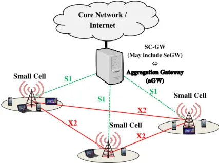
The logical architecture for 3G small cells is shown in Figure (1.1a). 3GPP has defined three variant for 4G small cells architectures (Figures (1.1b), (1.1c) and (1.1d)). The variants differ from each other in terms of the deployment of Small Cell Gateway (SC-GW) in the system or not, and when deployed whether it terminates the control plane only or both the control and user planes. Those variants were standardized in order to meet different operator deployment scenario requirements.
LTE is characterized by the introduction of new interface between access nodes for handover and interference managements: it is the X2 interface. As 3G/4G macro cells characteristics and functions apply to 3G/4G small cells respectively, two facts are made: 1) 3G small cells are not connected to each other, and 2) 4G small cells are connected to their neighbors small cells via X2 interface.
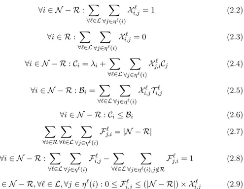
In this thesis, the focus is given to LTE small cells rather than 3G small cells. Table 1.1 [5]-[36]-[51]-[37] describes the differences between the three LTE SC architecture variants. Tables 1.2 and 1.3 [5]-[36]-[51]-[37] compare the advantages and limitations of each variant, by considering the messaging impact of main used protocols. The im-pact of transport layer protocols like Stream Control Transmission Protocol (SCTP) and User Datagram Protocol (UDP), and of the data carrying protocol GPRS Tun-neling Protocol (GTP) are discussed. Table 1.4 summarizes the applicability of each variant to different operator deployment scenarios.
As introduced before, the main scope of this thesis is the deployment of small cells for coverage in green-fields. The number of deployed SCs nodes is expected to be quite huge to support end users requirements. For this reason, the variant 1 of 3GPP LTE architecture is kept as reference architecture for this work. Variant 1 is the most suitable architecture for a large deployment of small cells in distant sites from operator transport network. Figure 1.2 summarizes the considered small cells
Chapter 1. Smal l Cel ls Networks: T echnolo gic al Glimpse Small Cell (SC) Small Cell Gateway (SC-GW) MSC/VLR SGSN Uu luh lu-CS lu-PS Security Gateway (Se-GW) Small Cell Management System (SCMS) User Equipment (UE)
(a) 3G Small Cells Architecture
User Equipment (UE) Small Cell (SC) Small Cell Gateway (SC-GW) MME S-GW LTE-Uu S1 S1-MME S1-U Security Gateway (SeGW) Small Cell Management System (SCMS)
(b) 4G Small Cells Architecture (Variant 1)
User Equipment (UE) Small Cell (SC) MME S-GW LTE-Uu S1-MME S1-U Security Gateway (SeGW) Small Cell Management System (SCMS)
(c) 4G Small Cells Architecture (Variant 2)
User Equipment (UE) Small Cell (SC) Small Cell Gateway (SC-GW) MME S-GW LTE-Uu S1-MME S1-U Security Gateway (SeGW) Small Cell Management System (SCMS)
(d) 4G Small Cells Architecture (Variant 3) Figure 1.1: 3GPP Small Cells Architecture
Core Network / Internet Small Cell X2 X2 X2 S1 S1 S1 Small Cell Small Cell SC-GW (May include SeGW)
Aggregation Gateway (aGW)
Figure 1.2: Aggregated Cellular Small Cells Architecture
1.2.2 Operator WLAN
Wireless LAN technologies are an excellent broadband complement for the operators’ existing 3G/4G services.
Figure 1.3 shows a simplified version of an operator WLAN architecture in non-roaming model. Only connections between the WLAN access and Operator core networks are described herein [4]-[10]-[61].
Network elements:
• WLAN UE: a WLAN UE is the User Equipment that may be capable of WLAN access only, or it may be capable of both WLAN and 3GPP radio access.
• Access Point (AP): it represents the access node on the network and is as-similated to be the WLAN small cell. It is the central transmitter and receiver of wireless radio signals and ensures broadband access to WLAN UEs. An AP can operate independently if the wireless network is established over a small distance, or managed by a controller in large area wireless networks. Some APs support mesh networking by allowing a radio for clients and other(s) for point to point connection to other(s) AP(s).
Table 1.1: Specifications of 3GPP LTE Small Cells Architectures Variants
Variant 1 Variant 2 Variant 3
Description SC-GW serves as a concentrator for both C-Plane and
U-Plane. C-Plane and U-Plane of SC are terminated in MME and S-GW respectively. SC-GW is deployed and serves as a concentrator for the C-Plane. The user plane of SC is
terminated in S-GW. SC The Access Point: it supports the same functions as a
Macro Cell and same procedures to/from EPC as the Macro Cell too.
SC-GW SC-GW connects between MME/S-GW and SC No SC-GW: SC is directly connected to MME and S-GW SC-GW connects between MME and SC and the latter is directly connected
to S-GW SeGW It is a mandatory logical function between SC and core
network elements (SC-GW if present and S-GW/MME). The SeGW may be implemented either as a separate physical entity or co-integrated with an existing entity. The
SeGW secures the communication from/to the SC.
• Access Controller: in large scale areas where many access points are deployed, it is necessary to use an access controller to manage them. Controllers perform more critical functions for WLAN access maintenance, such as APs configura-tion, interference managements and load balancing. The AC may enable local Intranet/Internet access for the WLAN access network.
• WLAN Access Gateway (WAG): it is a gateway that ensures Packet Switched (PS) data carrying between the the WLAN access and operator networks. It is the interworking point between the WLAN access and cellular services net-works. It collects information related to charging and per tunnel accounting and enforces routing of packets through the PDG.
• 3GPP Authentication, Authorization, and Accounting (AAA) Server: It is located in the 3GPP network. An attached WLAN subscriber is associated
Table 1.2: Advantages of 3GPP LTE Small Cells Architectures Variants
Variant 1
1) More secure architecture (MME and S-GW IP addresses are hidden from SC.)
2) Less SCTP associations to the MME: less SCTP messages overload in the MME and hence less CPU processing.
3) Enhanced S-GW scalability for UDP/IP and GTP protocols: S-GW manages less UDP/IP paths and GTP Echo messages which enables to deploy more SCs.
4) This variant allows to implement many mechanisms in the SC-GW such as: Paging optimization, Traffic offload, Denial of Service (DoS) and Handover optimization. Those mechanisms permit to unload and protect core network elements.
Variant 2
1) Less failure points in the system: a SC failure will not affect other SCs functioning.
2) Lower latency and reduced system level processing is achieved: direct connection to the core network elements. 3) Less upgrade/compatibility issues in supporting new releases features since SC-GW is not deployed.
4) SIPTO gateways can be deployed in distributed manner.
Variant 3
1) Less SCTP associations to the MME: less SCTP messages overload in the MME and hence less CPU processing.
2) This variant allows to implement many mechanisms in the SC-GW such as: Paging optimization and Handover optimiza-tion. Those mechanisms permit to unload and protect core network elements.
3) Lower latency and reduced system level processing is achieved in U-Plane: direct connection to the S-GW.
only to one 3GPP AAA server. It performs all Authentication, Authorization, and Accounting (AAA) procedures as for a cellular UE. A 3GPP AAA proxy interconnects between 3GPP AAA Server and WAG in roaming models; it is a proxying and filtering function located in the 3GPP network.
• Packet Data Gateway: it is the cellular gateway (3G/4G) that allows to access 3GPP PS based services. It acts as an anchor for user plane mobility and performs most of its functions as for a cellular access network (e.g. user
Table 1.3: Limitations of 3GPP LTE Small Cells Architectures Variants
Variant 1
1) SC-GW performs GTP-U tunnels switching in down-link/uplink: this infers on a U-Plane processing load propor-tional to traffic.
2) Less flexibility in redundacy and load sharing since a SC connects to a single SC-GW at one time.
Variant 2
1) Distributed SSCBC/GTP-U connections and UDP/IP con-texts leads to overload situation in MME and S-GW, which increases CPU processing load in the core network especially in huge SCs deployments.
2) In case dedicated MME/S-GW are required to solve overload problem, additional GW relocation load should be processed.
Variant 3
1) No GTP-U connection concentration leads to overload situ-ation in the S-GW due to UDP/IP contexts and GTP-U Echo messages, especially in massive SCs deployments.
2) Less flexibility in redundancy and load sharing in C-Plane since a SC connects to a single SC-GW at one time.
traffic filtering for QoS differentiation, WLAN UE IP address allocation, etc). • Wu: it is located between the WLAN UE and the PDG and is transported by
Ww, Wn and Wp reference points. It is not a direct interface between WLAN UE and PDG but represents an initiated tunnel for data between the two elements.
• Wn: it is the reference point between the WLAN Access Network and the WAG. It forces the traffic crossing via the WAG on a WLAN UE initiated tunnel.
• Wp: it is the reference point between the WAG and PDG and would be defined by the operator/technology.
• Wa: it is the reference point between the WLAN Access Network and the 3GPP AAA Server. It serves to transport authentication, authorization and charging information, possibly via intermediate networks, in a secure manner.
• Wm: it is the reference point between the 3GPP AAA Server and PDG. It serves to carry user AAA messages between the two elements.
Table 1.4: Applicability of 3GPP LTE Small Cells Architectures Variants
Variant 1
1) A good choice for the operator to a fast and cost-efficient migration from a 3G to 4G SC solution for two main reasons: i) this variant is comparable to 3G SC architecture terminat-ing both control plane and user plane in the Gateway, and ii) existing GW infrastructure components (Platform/ Hardware Reuse, User plane handling / GTP functionality reuse) can be easily reused and upgraded.
2) It is a beneficial solution for new and massive LTE SCs de-ployments: as many mechanisms are handled by the SC-GW, the core network is protected from huge processing load of nu-merous SCs nodes. It also allows to minimize the impact of EPC as much as possible when number of deployed SCs is increasing.
Variant 2
1) For 4G upgrade deployments, this variant can re-use SeGWs and transport infrastructure from 3G architecture.
2) This variant is beneficial in deployments scenarios where the number of SCs is limited to a threshold that reduces cost effect and does not create scalability issues on the core network. It relates essentially to residential deployments, but still depend on MME capacity to handle SCBC connections.
Variant 3
1) For 4G upgrade deployments, this variant can re-use SeGWs and transport infrastructure from 3G architecture.
2) As the number of deployed SCs increases, S-GW scalability requirements increase too. Fair evaluation of UDP and GTP contexts impact should be considered on case by case basis.
It is an AAA interface. It provides the WAG with necessary information to perform policy enforcement functions for authorized users.
WLAN Terminals Access Point (AP)
WLAN Access
Network
Access Controller (AC)Intranet/
Internet
WLAN Access Gateway (WAG) 3GPP AAA Server Packet Data Gateway (PDG)Operator Core
Network
Wa Wn Wg Wm Wp Wu (IPSec)Figure 1.3: A simplified Operator WLAN architecture
1.3
Small Cells Wireless Backhaul Requirements
The backhaul is the network segment that provides connectivity between access nodes (i.e. small cells) and core network at a certain level of QoS, and between access nodes themselves. The backhaul is made up of a set of transport network aggregation points that ensures the connectivity function it is designed for. Namely, the backhaul possesses at least one Point of Presence (PoP) or Point of Concentration (PoC). The PoP/PoC acts as a central aggregation point for different small cells traffic towards the core network. By referring to our SCs reference architecture (figure 1.2), the aGW (i.e. SC-GW) may play this role. Actually, the aGW may either aggregate many SCs and being itself aggregated by a PoC, or may enable both aggregation and connectivity for the SCs. In this thesis, the focus is given to the part between SCs and the PoC node; connectivity between the PoC and operator core network is assumed to be available whatever the access solution is.
In the following subsections, main challenges that face small cells wireless bakchaul in green-field deployments are discussed [58]-[57]-[38]-[14]-[26].
1.3.1 Connectivity
Furnishing a good quality connectivity between SCs and core network is strongly associated with PoC coverage: it denotes the area where a set of SCs can connect to the PoC at minimum quality. Indeed when wireless technologies are intended to be used in the bakchaul, Line-of-Sight (LOS) or Non Line-of-Sight (NLOS) links and Point-to-Point (PtP) or Point-to-Multipoint (PtMP) communications should be considered.
LOS wireless links requires clear links -without/with minimum physical obstructions-between SCs and PoC. In this case, wireless links may suffer from atmospheric at-tenuation [53]-[54] and long distances. NLOS wireless links can be considered: used alone or coupled with LOS ones. It all depends on the physical characteristics of the service area to cover with small cells and operator network availability.
In green-field deployments where the PoC is supposed to serve large areas with numerous SCs, it is more convenient to favor PtMP communications since it does not require antenna alignment. Yet PtMP communications endures low capacity due to huge SCs traffic multiplexing and limited spectrum availability at lower frequencies.
Depending on cost requirements and operator availability, small cells covering an area can be connected to any connectivity node that offers most convenient backhaul. A small cell can either connect directly to the PoC (and/or aGW) or to another small cell. The operator may use a mixture of tree and mesh topologies to provide an effective connectivity.
1.3.2 Throughput/Capacity
The backhaul capacity must at least fulfill the entire associated small cells capaci-ties. Moreover, it should follow future traffic growth and support its daily variations. Considering the worst case scenario when dimensioning the backhaul capacity is not an efficient solution since it would lead to an over-provisioning. In fact, a high provi-sioning level for backhaul capacity means that more PoCs and links are needed and higher capacity links are required. The backhaul solutions are hence more expensive and can be more complex to deploy.
A backhaul provisioning method was adopted by the NGMN Alliance [11] that takes into consideration two load cases of the network: busy hours and quiet hours.
Actu-ally, wireless backhaul is very sensitive to available bandwidth, shared radio resources and signal noises. This implies that an end user throughput depends on the quality of its radio link. During busy hours, many end users devices share the small cell resources: it is unlikely that all users have a link good enough to transmit/receive at maximum spectral efficiency. Consequently, the required capacity by the small cell corresponds, in this case, to the mean capacity of all its users. During quiet hours, it is generally one end user device that can use the entire small cell resources. When its radio link is of a good quality, this user can reach the peak throughput. In this case, the small cell capacity’s need is measured by report to this value. However, end users throughput fluctuates depending on various parameters. By assuming that busy time means do occur simultaneously and that quiet time peaks do not, the backhaul capacity provisioning for N small cells is obtained as: Max (peak, N × busy time mean). Nowdays, a 3G/4G link may require up to 60 Mbps in uplink an 200 Mbps in downlink [60] depending on 3GPP’s feasibility study on LTE Advanced [9]. The simulations pointed out how cell spectral efficiency in the microcell environment is on average 25% higher than in the macrocell environment. Although the analysis focused on dense deployments, small cells spectral efficiency is assumed to be 1 to 1.25x to macro cell spectral efficiency.
1.3.3 Delay
Mobile broadband is foretasted to include a great amount of delay-sensitive services, especially the ones that require real-time interaction such video conferencing, gam-ing, etc. Delay and jitter degradation impacts the Quality of Experience (QoE) of these services users. Not only data traffic may be impacted by end-to-end delay degradation, but also signaling messages (e.g. X2 signaling for interference cancella-tion). As the end-to-end delay is measured between the user terminal and the service server, the backhaul, connecting radio to core, contributes in this delay.
3GPP introduced to the LTE networks the QoS Class Identifier (QCI) mechanism that allows to allocate appropriate QoS. 3GPP recommends in [69] packet delay budgets for many service types depending on their QCIs. The recommended delay budget from the UE to the EPC ranges from 50 ms (i.e. gaming) to 300 ms (i.e. default best effort). Those recommendations are made for worst case scenario, hence they represent the minimum acceptable QoE; operators may exceed those figures at reasonable level.
When establishing the delay budget, it is necessary to identify the network compo-nents that will be involved in this delay. Typically, there are compocompo-nents that are always deployed, which introduce their own delay, such as radio interface or trans-port segment between the PoC and CN; other components are not always deployed and their delay impact is considered per use case solution: SC-GW is an example. Moreover, the backhaul delay remains negligible compared to the largest latency generated by any other component. The SCF [34] suggests these small cell backhaul delay assessments:
• < 1ms: Negligible
• 1-10ms: Low
• 10-60ms: Acceptable
• > 60ms: Acceptable/Depends on the service
1.3.4 Security
The SCs backhaul security requirements is based on the assessment of SCs network: trusted or untrusted. The trusted/untrusted notions are introduced by 3GPP [7] depending on different trust criteria; for example: operator security level, physical site locations control, network management levels, etc. The 3GPP specifies to im-plement an extra mandatory layer of security for untrusted networks. A customized investigation should be conducted by the operator in order to evaluate eventual risks.
As for the macro cells, it is assumed that 3G/4G small cells backhaul belongs to trusted networks as stated by 3GPP architecture models [6]. The IPSec framework is adopted for such networks as recommended by 3GPP. The operator still has the choice to deploy or not IPSec communications; however it is preferable to implement it since it would prevent any potential vulnerability.
The communications between a small cell and the core network should be secured by IPSec tunnels. The IPSec framework ensures data integrity, authentication and confidentiality to guarantee the end-to-end service protection [12]. As introduced in subsection 1.2.1, a small cells network deployment should include a mandatory Se-GW, either as an integrated logical function with SC-GW or one of EPC, or as a separate physical node. The operator is free to choose the implementation point/way of the Se-GW depending on its deployments requirements.
![Figure 1.4: Mobile Backhaul TCO components [49]](https://thumb-eu.123doks.com/thumbv2/123doknet/11554710.296692/55.892.132.722.156.558/figure-mobile-backhaul-tco-components.webp)