HAL Id: hal-00804479
https://hal.archives-ouvertes.fr/hal-00804479
Submitted on 25 Mar 2013
HAL is a multi-disciplinary open access
archive for the deposit and dissemination of
sci-entific research documents, whether they are
pub-lished or not. The documents may come from
L’archive ouverte pluridisciplinaire HAL, est
destinée au dépôt et à la diffusion de documents
scientifiques de niveau recherche, publiés ou non,
émanant des établissements d’enseignement et de
integration in Small and Medium Enterprises networks
Julien Le Duigou, Alain Bernard, Nicolas Perry
To cite this version:
Julien Le Duigou, Alain Bernard, Nicolas Perry. Framework for Product Lifecycle Management
inte-gration in Small and Medium Enterprises networks. Computer-Aided Design and Applications, CAD
Solutions LLC (imprimé) and Taylor & Francis Online (en ligne), 2012, pp.1-14. �hal-00804479�
Framework for Product Lifecycle Management integration in Small and
Medium Enterprises networks
Julien Le Duigou1, Alain Bernard1, Nicolas Perry2
1IRCCyN, Ecole Centrale de Nantes, [email protected],
2LGM2B, Université de Bordeaux1, [email protected]
ABSTRACT
In order to improve the performance of extended enterprises, Small and Medium Enterprises (SMEs) must be integrated into the extended networks. This integration must be carried out on several levels which are mastered by the Product Lifecycle Management (PLM). But, PLM is underdeveloped in SMEs mainly because of the difficulties in implementing information systems. This paper aims to propose a modeling framework to facilitate the implementation of PLM systems in SMEs. Our approach proposes a generic model for the creation of processes and data models. These models are explained, based on the scope and framework of the modeling, in order to highlight the improvements provided.
Keywords: PLM, Enterprise modeling, Information System. DOI: 10.3722/cadaps.2011.xxx-yyy
1 PRODUCT LIFECYCLE MANAGEMENT NEEDS AND DIFFICULTIES IN SMALL AND MEDIUM ENTERPRISES
Due to globalisation, enterprises have to work in networks which are increasingly diversified and geographically dispersed. To reach cost, quality and delay optimisation, enterprises implement new information and communication technologies. The Small and Medium Enterprises (SMEs) also try to implement those technologies but, despite their flexibility, they have difficulties in structuring and exchanging information. SMEs also have problems in creating data models for structuring and sharing product information, especially in the context of extended enterprises. This section introduces the functionalities of Produt Lifecyle Management (PLM) systems, explores the existing product models for PLM, and presents the PLM situation in SMEs. Section 2 presents a modelling framework to create models for PLM in an extended enterprise context and explains how to use the framework. Section 3 presents a demonstrator, based on the developed generic model, in order to validate the global proposal. Discussion and perspectives conclude this paper.
CimData [1] define the PLM as “a strategic business approach that applies a consistent set of business solutions in support of the collaborative creation, management, dissemination and use of product definition information across the extended enterprise from concept to end of life - integrating people, processes, business systems, and information”. PLM encompasses not only the definition of the product, but also the definition of the product lines, the technologies used, the organization and
the services associated to the product (services during its use, but also during its maintenance, end of life etc.).
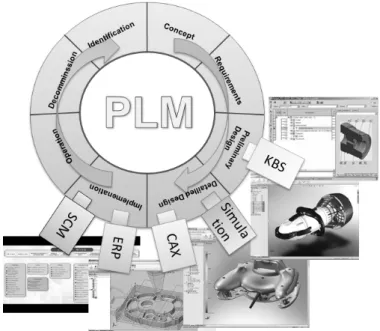
PLM is supported by business software. Links between the PLM systems and other software (Figure 1), such as Computer-Aided Design (CAD), Computer-Aided Manufacturing (CAM), Enterprise Resource Planning (ERP), and Supply Chain Management (SCM) etc. ensure diffusion, traceability, archiving and reuse of information [2]. The PLM systems help to pass the product definition information from one business solution to another. Interoperability and modularity are important issues in those systems [3, 4]. Product meta-models help to support this interoperability by structuring product information that can be easily accessed by the different actors involved in product development.
Fig. 1: PLM and business software
One main difficulty lies in the implementation of the product meta-model, due to the fact that SMEs have to integrate the different information structures of their customers. Different surveys [5, 6, 7] show that the main difficulties that arise for the implementation of PLM system for SMEs are:
The difficulty of modelling (both processes of the company and exchanged data). There are not enough modelling skills in SMEs due to the critical size of the information systems' internal services.
The lack of interoperability between the different information systems inside (PLM, CAD, ERP) and outside the enterprise (PLM of partner companies).
To provide adequate modelling concepts and modelling methods enabling the integration and structuring of multidisciplinary product data is one of the main point for acceptance of PLM solution especially in SMEs [8]. Product modelling was introduced to manage product information in a multi-view and multi-actor context. FBS-PPRE [9] and IPPOP [10] proposals aimed at structuring information, Gzara developed patterns [11] to focus on reuse, STEP AP214 [12] or STEP AP239 [13] focus on exchange. In the context of PLM systems, these generic models should be adapted.
The use of these models in an industrial context requires modifications, adaptations and specializations. El Khalkhali [14] or Euler Chaplin [15] deal with the specialization and consolidation of generic models, especially STEP. They use a top-down approach to adapt the models to the reality, and do not fully meet industrial needs. Bacha [16] and Abdmouleh [17] use the Zachman framework [18] or the Cimosa cube [19] with a bottom-up approach to create their own models but they lose the benefit of interoperability of the generic model.
Numerous projects, like Promise [20] or Bridge [21], propose methods and models exploiting the whole product lifecycle information in so called closed-loop PLM. It includes the phases of use, maintenance and end of life in the collection of data. The produced data for the whole lifecycle are now availiable. For example RFIDs, embedded systems and wireless communication allows collecting information during the use or maintenance phases. Those projects lead to describe data models adapted to the encapsulation of knowledge and data from the product all over the lifecycle. Those models and ontologies, like in [22], included the product definition “as designed” but also “as built” and “as maintained”. The goals of those models, like in Cassina [23], is to improve the interaction between the enterprise and the customer.
These models are more adapted to some kind of companies, especially in a business to consumer (B to C) economic model, than to the mechanical SMEs present in our work, like primary part manufacturers. Indeed the closed-loop PLM is more valuable when the interaction is direct between the company and the end user of the product. In the case of a second or third rank supplier, this interaction seems to be more difficult. Moreover the focus of our work is also more specific, focusing on the “as designed” product definition for all the lifecycle phases, which is the first step of the implementation of a more holistic approach, including the product definition “as built” and “as maintained”, that need more investment and more skills, not yet avalaible in the mechanical SMEs.
The next section will present our research approach to create a modelling framework based on a bottom-up method to obtain a generic model for an SMEs network, and a second refinement phase to adapt the generic model for a specific company of the network.
2 MODELLING FRAMEWORK
A bottom-up approach is proposed to create a generic meta-model. The generic model could be afterwards specialized to fit the specific needs of each SME.
The approach begins with an inductive step formalizing the generic model. A three-month immersion in three representative companies highlighted the needs concerning PLM in SMEs. Moreover, this analysis revealed the processes that should be implemented in order to address these needs. Finally, the data structures that can automate these processes are created. These results were then aggregated to create a generic model (Figure 2).
2.1 Creation methodology
After the AS IS audit of the three pilot enterprises, we obtained three requirements’ maps, three processes models and three data models. These partial models will be combined to form a global representation. We assume that the three enterprises are a representative sample of SMEs (part manufacturer, component manufacturer and equipment manufacturer).
The main problems of each enterprise were identified and detailed in [24]. A list of PLM needs has been created from those immersions, focusing on those that are not fully implemented in the actual PLM systems. Following our study, six classes of needs have been identified, depending on the type of enterprise and its activity:
Configuration management: This comes from the equipment part manufacturers. The PLM systems must manage the alternatives, the options, the versions, the families and the differentiation between internal and external products.
Collaboration: The exchange with the customers (from the parts and components manufacturers) and with the suppliers (from the components and equipments manufacturers) must be facilitated and standardized, especially for the CAD file exchanges.
Multiple views: The information has to be visible with the structure and the names of each department. This is particularly needed for the Bill of Material (BoM) in design and production departments, corresponding to the structures of the CAD and the ERP software.
Process planning: The raw parts’ manufacturers need the process plans and the information included (operations, work centres, tools, etc.) to be managed by the PLM systems.
Interoperability: The interoperability with the ERP and the CAD is required by the three types of SMEs, especially for the BoM and process plans updates.
Decision aid indicators: Cost is the most commonly requested indicator to compare product alternatives for the equipment manufacturers or, for the parts manufacturers, to choose between alternative operations in a process plan.
These needs have to be addressed by the PLM systems in order to interest the SMEs. The processes implemented in the three pilot enterprises give a solution for those needs. This process generalization should help to solve the global needs. The detailed levels of the IDEF0 [25] (that represent the processes as a sum or sequence of activities) point out the intermediary objects. The same intermediary objects are in several companies, continuing their life cycle passing from one company to another. These exchanges enable the processes from one company to another to be linked, such as in an extended enterprise.
The process data model includes the objects that appear as input and output of the activities. The aggregation of those results enables a generic model for the SMEs to be defined. To generalise these specific models into one generic model, the following method is applied:
1. Select the objects that deal with PLM. The specific models contain specific objects regarding the company’s business.
2. Group objects by theme and identify the meta-concepts and the generic objects representing each group. This phase is performed by a cognitive analysis of the modeller based on a semantic analysis.
3. Detail the generic objects. This step is performed by an extraction of the intersection of attributes and methods.
4. Link the different generic objects. This is done by identifying the various links between specific objects of different groups.
This process is applied to the three data models obtained from the representative pilot companies to create the generic meta-model.
2.2 Generic meta-model
The different identified meta-objects are organized into four main packages represented in a UML class diagram in Figure 3. The activity package groups activities such as projects and process planning. The product package groups the products produced by the enterprise and all their components. The resource package groups the work centres, the tools, the humans and the software of the company. Finally the organization package groups suppliers, customers and collaborators of the company.
Fig. 3: UML class diagram of the meta-model
The product model (Figure 4), the activity model (Figure 5) and the resource model (Figure 6) will be explained. The organization package links the different objects in the extended enterprise context.
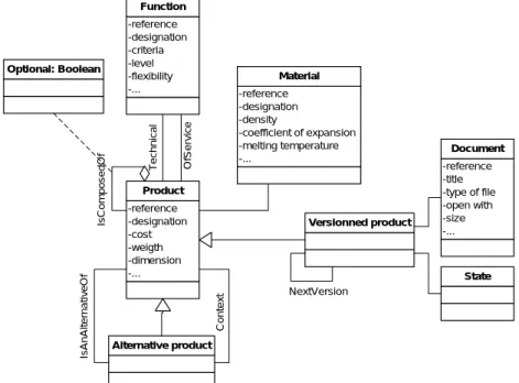
2.2.1 Product meta-model
The product is composed of products, which may be optional. A component can have alternative components in an assembly context. Moreover, the product has different versions, defined by states (creation, validation, validated, obsolete etc.) and attached documents. The product is linked to the activity through input and output. A product may be the output of an activity and the input of another. The structure of the product by product (assembly) – activity – product (component) breakdown gives different structures, depending on the breakdown activity (assembling, maintaining, decommissioning etc.). The product is also connected to the function, as a technical function or a service function, via the selected link. A technical function for a component in an assembly becomes a service function for this component when it is alone. This design enables us to have a functional view of the product structure by a breakdown product (assembly) – technical function - service function– product (component). -reference -designation -cost -weigth -dimension -... Product Alternative product -reference -title -type of file -open with -size -... Document Versionned product State Optional: Boolean -reference -designation -criteria -level -flexibility -... Function -reference -designation -density -coefficient of expansion -melting temperature -... Material Is AnAl te rnat iv eOf Co nte x t NextVersion Is Compo s edOf T e chni ca l OfServ ic e
2.2.2 Activity meta-model
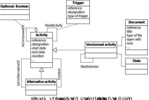
An activity has versions that have states and documents. An activity can be composed of other activities. An activity can have an alternative activity in a parent activity context (i.e. a process). In addition, the activities are ordered through the link “next activity”. A trigger activates this link to go from one activity to the other.
-reference -designation -start date -end date -duration -... Activity Alternative activity -reference -title -type of file -open with -size -... Document Versionned activity State Optional: Boolean -reference -designation -type of trigger Trigger NextVersion NextActivity
Fig. 5: UML class diagram of the activity meta-model
2.2.3 Resource meta-model
The resource also has versions, with states and documents. The resource can be composed of other resources. The resource may have an alternative resource for a given activity.
-reference -designation -capacity -hourly rate -setup time -... Resource Alternative resource -reference -title -type of file -open with -size -... Document Versionned resource State Optional: Boolean -reference -designation -start date -end date -duration -... Activity NextVersion Context IsAnAlternativeOf IsCo mp ose d Of
All the objects have attributes and methods created with the same approach as for the objects themselves. The classical attributes (creator, date of creation, date of modification etc.) and methods (create, delete etc.) are not shown on the diagrams for reasons of simplicity.
This meta-model must be specialised in order for it to be applied to a specific company of the network. The specialization method is described below.
2.3 Specialization of the meta-model
2.3.1 Presentation of the framework
To reach the specific needs of the companies and obtain specific models, the objects of the generic model are specialized for each domain and for each company. Three levels are used:
The generic level has been defined in this paper, and can be used in all kinds of companies. The partial level is specialized from the generic model and expresses all the objects of one
particular domain (e.g. machining, forging, stamping, etc).
The particular level is the company model, instantiated from the partial model (or directly from the generic model, if the partial model does not exist).
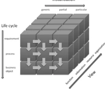
The framework proposes a system with needs, processes and data models coherent for the three pilot enterprises. Figure 7 shows the framework adapted from GERAM [26] with an abscissa representing the needs, processes and business objects. The ordinate represents the instantiation of components: generic, partial or particular levels. And the depth represents the different views of the system: function, information, resource and organization. The difficulty of formalizing the processes and creation of a data model for a PLM system is reduced by the pre analysis and the selection of objects in an already existing panel.
Fig. 7: Modelling framework adapted from GERAM
2.3.2 Method to make the specific model
To make the company-specific models, the proposed method is to re-play the same process used to reach the generic model definition. It begins with a needs analysis then continues with the formalisation of the processes that are necessary to address these needs. The third step is the extraction of business objects involved in these processes.
Identifying needs: Needs are identified through interviews, observations and immersion in the company. Mind maps are used to formalise the requirements with the company experts. This identification is facilitated by the possibility of selecting the generic needs proposed in the generic map.
Process definition: Process modelling is done with the experts. IDEF0 diagrams are used to formalise the processes. These processes are deduced from both the identified needs and the corresponding generic processes.
Definition of business objects: The identification of objects is done by extracting the inputs and outputs of processes defined in step 2. Based on the generic model, the specialization of the generic objects leads to specific objects of the company. The UML class diagrams are used to formalise the objects of the company.
2.3.3 Evolution of the specific model
The company requirements change over time. Most of the changes can be managed directly with the proposed model. Those changes can be handled by the specialization of the existing objects, as described further in the product families’ functionality. The addition of a new product family, a new organization of the departments, a new supplier type or a new market is done by adding a class specialization of product, organization, supplier or customer.
Nevertheless, if the generic objects cannot cover a new need of a company, it is still possible to add new generic objects using the methodology described above. The methodology is still a three steps process: Identify the new need of the company, define the process to respond to this new need and define the business objects used in this process.
3 APPLICATION
To verify that the meta-model proposed is sufficient to cover the PLM functionalities in SMEs, a demonstrator integrating the meta-model is created. The use of the objects in the different functionalities is shown by instantiating the part of the meta-model used and then showing the result in the demonstrator. At the end the validation of the meta-model is done by its possibility to respond to the required functionalities.
3.1 Architecture
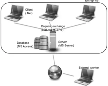
A software demonstrator is created to automate the use of the framework in an industrial context. The architecture of the demonstrator is a rich client/ server one (Figure 8). The client is developed in VB.Net and the server uses MS SQL Server. They communicate through SQL requests via http/https.
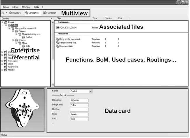
The proposed generic model is implemented in the demonstrator, with the generic classes, attributes and methods. Each class can be specialized into sub-classes, inheriting of the attributes and methods of the father class. New attributes could be added to the new class. A new specialization is applicable to the sub-classes and so on. The interface is constituted of a tool bar with the multiple views, a tree view to represent the enterprise referential, a file view for the associated files and the different linked objects, a data card and a viewer (Figure 9).
Fig. 9: Demonstrator’s interface
3.2 Functionalities
The application is chosen to cover the maximum of identified needs. The study needs are: the configuration management, the link with the supplier, the multiple views, the link with the CAD and ERP, the process plans management and the cost indicator.
The configuration management is partially covered by actual PLM systems. It is principally a request from the equipment manufacturer. The creation of a product family and the differentiation between internal and external products is nevertheless simplified in the demonstrator.
To create a product family, the user right clicks on the generic class of a product on the tree view and selects new. A new sub-class (a family of products) is created, inheriting the attributes of the product class plus the new ones that the user defines for this family (Figure 10). Each product created in this family will have the attributes of the family. Sub families can be created reproducing the same method in a family.
Fig. 10: UML class diagram and treeview of the product family
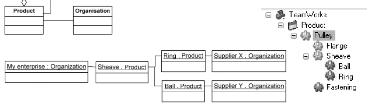
The internal and external products are in the referential of the enterprise with different colours (yellow for the internal products and green for the external products). The different suppliers identified are present in a specific folder. A drag and drop from a component of the supplier to the demonstrator imports the product, all the attributes and the attached files. If the supplier has installed the same system, the external product can be taken directly from the supplier PLM system. The supplier selects the products he wants to sell and they are then accessible directly by his customers. If a new version of a product is placed in this folder, a notification is sent to the customers that use the old version, etc…
Fig. 11: UML class diagram, UML object diagram and treeview of the differentiation between internal and external products
The composition of a product is not the same depending on the user’s work in the enterprise. There is no universal view for all the business units and each business view gives advantages to their users. In the present work, three views are considered: functional, structural and manufacturing.
In the structural view, the components of the product are decomposed in the tree view (Figure 12).
To obtain a functional view, the user has to change the view by clicking on the function button. Then he can create functions under the product (the internal functions) and add in the components of the product (the functions of service of the components) (Figure 13). So the product is decomposed from a functional point of view.
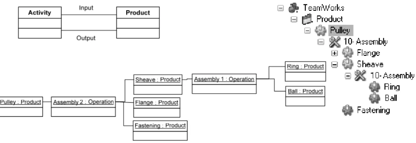
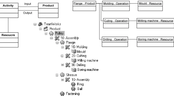
Fig. 13: UML class diagram, UML object diagram and treeview of the functional view of a product In the manufacturing view, the assembly operations are linked to the product and to the component (Figure 14). This gives a manufacturing structure of the product through a product – assembly – component decomposition of the product.
Fig. 14: UML class diagram, UML object diagram and treeview of the manufacturing view of a product
In each view, some objects can be added separately. The object is visible in the selected view and not in the others. It could be the case for the addition of grease in the manufacturing BoM that does not have to be visible in the design BoM.
Other views can be added in the model by adding a new step of the product lifecycle specializing the activity class (such as: operation is the specialization of activity in the manufacturing view). For example, a disassembly activity class can be created and the different links between the product and the disassembly activities create a "End of Life" view of the product. Those functionalities are not yet integrated in the demonstrator but are available in the framework.
The interoperability of the PLM systems with the CAD and the ERP systems are the most important links to create [6]:
For the CAD link, the designer imports the assembly tree view of the product with a drag and drop of the CAD file from the desktop to the demonstrator. The CAD tree view is then copied in the structure view. The components are created and the corresponding CAD files are imported into the right component objects. With the import of the CAD file, a link is created between the CAD attributes and the object attributes (for the attributes with the same name in the CAD system and in the demonstrator). Those attributes are then synchronized. When a change happens in the CAD file, the PLM system notifies the product owner in the PLM. The owner can accept the modification and the change will be transmitted to the PLM and vice versa. The implementation is done on SolidWorks from Dassault Systems.
The manufacturing view can be synchronised with the ERP of the enterprise to obtain up to date BoM and process plans. A mapping with an ERP is implemented in the demonstrator. It synchronises the items, the operations, the work centres, and all their respective attributes, updating the BoM and the process plans. If a modification occurs in the ERP information, an email is sent to the owner of the modified product in the PLM and he can accept the modification to impact the PLM information. This is done on the ERP EFACS from EXEL Computer System, using the database Informix from IBM.
The management of the process plans directly in the PLM systems is a priority for the components and raw parts manufacturers. To create a process plan, the user creates the different operations in the product (Figure 15). He can define optional operations, alternative operations and external operations (appearing in green and not in yellow as the internal operations). Then he loads the resources useful to each operation dropping the input items, the work centres, the tools etc.
Fig. 15: UML class diagram, UML object diagram and treeview of the process planning Product cost is the most requested indicator to guide and help decisions for design and industrialisation in SMEs, including the cost of manufacturing processes. The cost concept is present in the demonstrator. To have an estimation of the cost of a product, the user must create the process plan of its product. It includes the components, the work centres and all the other consumables. Then the cost of each operation, each work centre and each component of the lower level of its decomposition is filled. Then the demonstrator calculates the estimated cost of the product.
The implementation of all functionalities in a demonstrator based on the proposed data model shows the usefulness of the model and its applicability.
4 DISCUSSION
The contribution of this work is on two levels: on the one hand a method of generalization of models for a generic model and specialization of the generic model to particular models and, on the other hand, a generic model for SMEs.
The generalization method creates a generic model of various specific models. Different departments or companies may have a common view of their product-process-resource information. The exchange and sharing of information is then facilitated. The difficulty of the method is the grouping of objects that inherit from a single generic object. This is done by a semantic analysis of object names and attributes, but in the present study, it was facilitated by the fact that the same modeller created the three specific models.
The specialization of the generic model gives a specific model adapted to the business of the company, but keeping the interoperability facilities with other companies that base their information system design on the same generic level.
The second point is a generic model for SMEs that meets the needs identified in the pilot companies. It can be specialized in a particular model for each new company or to each department which needs a specific model. The link with the rest of the extended enterprise is provided with the link to the generic model. The main weakness of this model is that it is based only on three case studies, even if they are representative of the mechanical and production engineering market.
A PLM demonstrator integrating the approach and the data model has been developed. The demonstrator implements the objects of the generic model and its specialization. The implementation of this demonstrator in a company on a major project will validate the robustness and the appropriateness of our approach. This demonstrator will be the base of new software developed by a new company created at the end of the first stage of this research work.
5 CONCLUSION
The SMEs need to integrate more and more extended networks. The PLM systems are efficient solutions if they are adapted to the SMEs structure and work. But the SMEs do not easily integrate the PLM systems. Their needs do not match the actual PLM functionalities. A framework to facilitate the processes and data modelling and to improve interoperability between their information systems is proposed. This work aims to give a framework to integrate their functionalities through the specialization of their data model according to their field of activity. The proposed Product Process Resource model is the result of the concatenation of models of three companies representing the needs of SMEs in terms of PLM. It may be specialized in specific models for each individual company. These specific instantiations are based on the same structure for a high level of interoperability. This work also provides a method of specialization to create specific data models of each particular company, ensuring greater interoperability through the alignment of high semantic models (for the PLM) with specialised models for other applications (ERP, CAD etc.). Finally a demonstrator illustrates the use of the PLM system to solve the identified needs, showing the technical feasibility and the applicability of our approach.
6 ACKNOWLEDGMENT
We would like to thank the CETIM to support this research and PSL CONCEPT, CAPRICORN and SMP companies for allowing us to carry out our study in their companies and for their technical support.
7 REFERENCES
[1] CIMdata Inc.: Product Lifecycle Management “Empowering the future of business”, 2003.
[2] Lund, J.G.; Fife, N.L.; Jensen, C.G.: PLM-based parametrics for design automation and optimization, Computer-Aided Design & Applications, 2, 2005, 37-45.
[3] Dutta, D.: Sustaining product innovation thru PLM, International Seminar on Product Lifecycle Management, 18-19 mars 2005, Noida, India.
[4] Jaekel, F.W.; Perry, N.; Campos, C.; Mertins, K.; Chalmeta, R.: Interoperability Supported by Enterprise Modelling, in Lecture Notes in Computer Science - On the Move to Meaningful Internet Systems, Ed. R. Meersman, Z. Tari, P. Herrero, Springer-Verlag, Vol 3762, p.552-562, 2005, ISBN 3-540-29739-1.
[5] Terzi, S.; Garetti, M.: Implementing PLM projects: evidences from practice, Proceedings of 6th International Conference on Product Lifecycle Management, 2009.
[6] El Kadiri, S.; Pernelle, P.; Delattre, M.; Bouras, A.: Current situation of PLM systems in SME/SMI: Survey’s results and analysis, Proceedings of 6th International Conference on Product Lifecycle Management, 2009.
[7] Cetim: Enquête de besoin sur le travail collaboratif, Document interne, 2007.
[8] Eigner, M.; Nem, F.M.: On the development of new modelling concepts for product lifecycle management in engineering enterprises, Computer-Aided Design & Applications, 7(2), 2010, 203-212.
[9] Bernard, A.; Labrousse, M.; Perry, N.: LC universal model for the enterprise information system structure, Innovation in Life Cycle Engineering and Sustainable Development, Ed. by D. Brissaud, S. Tichkiewitch & P. Zwolinski, Springer Ed., pp.429-446, 2006, ISBN 1-4020-4604-1.
[10] Noël, F.: A dynamic multi-view product model to share product behaviours among designers: how process model adds semantic to the behaviour paradigm, Int. J. Product Life Management, 1(4), 2006, 380-390
[11] Gzara, L.; Rieu, D.; Tollenaere, M.: Product information systems engineering: an approach for building product models by reuse of patterns, Robotics and Computer-Integrated Manufacturing, 19(3), 2003, 239-261.
[12] ISO 10303-214, Industrial Automation Systems and Integration - Product Data Representation and Exchange - Part 214: Application Protocol: Core Data for Automotive Mechanical Design Processes. ISO, 1998.
[13] ISO 10303-239, Industrial Automation Systems and Integration - Product Data Representation and Exchange - Part 239: Application Protocol: Product Life Cycle Support. ISO -, 2005.
[14] El Khalkhali, I.; Ghodous, P.; Martinez, M.; Fravel, J.: An information infrastructure to share product models using STEP standard, 9th IPSE international conference on concurrent engineering: research and applications, Cranfield University, 27th-31st July 2002.
[15] Euler Chelpin, von A.: Information modelling for the manufacturing system life cycle, Ph.D. Thesis, University of Stockholm, 2008.
[16] Bacha, R.: De la gestion des données techniques pour l’ingénierie de production. Référentiel du domaine et cadre méthodologique pour l’ingénierie des systèmes d’information techniques en entreprise, Ph.D. Thesis, École Centrale Paris, 2002.
[17] Abdmouleh, A.; Spadoni, M.; Vernadat, F.: Distributed client/server architecture for CIMOSA-based enterprise components, Computers in Industry, 55(3), 2004, 239-253.
[18] Zachman, J.A.: A frameworks for information systems architecture. IBM Systems Journal, 26(3), 1987, 276-292.
[19] Kosanke, K.; Zelm, M.: CIMOSA modelling processes, Computers in Industry, 40, 1999, 141-153 [20] PROMISE Research Deliverable 9.6: -
http://www.promise.no/downloadfile.php?i=877a9ba7a98f75b90a9d49f53f15a858, 2007.
[21] BRIDGE Final Report: http://www.bridge-project.eu/data/File/BRIDGE_Final_report.pdf, 2009. [22] Matsokis A. ; Kiritsis D.: An Ontology-based Approach for Product Lifecycle Management,
Computers in Industry, 61(8), 2010, 787–797
[23] Cassina, J.; Cannata, A.; Taisch, M.: Development of an Extended Product Lifecycle Management through Service Oriented Architecture, Proceedings of CIRP IPS2 Conference, 2009.
[24] Le Duigou, J.; Bernard, A.; Perry, N.; Delplace, J.C.: Global approach for product data management, application to ship equipment part families, CIRP Journal of Manufacturing Science and Technology, 1-3, 2009, 185-190.
[25] IDEF: Announcing the Standard for Integration Definition for Function Modeling, Draft Federal Information Processing Standards Publication 183, 1993.
[26] GERAM: Generalised Enterprise Reference Architecture and Methodology v1.6.3, IFIP–IFAC Task Force on Architectures for Enterprise Integration, 1999.