The vector-apodizing phase plate coronagraph:
design, current performance, and future
development
D. S. D
OELMANet al.*†
Abstract: Over the last decade, the vector-apodizing phase plate (vAPP) coronagraph has been developed from concept to on-sky application in many high-contrast imaging systems on 8-m class telescopes. The vAPP is an geometric-phase patterned coronagraph that is inherently broadband, and its manufacturing is enabled only by direct-write technology for liquid-crystal patterns. The vAPP generates two coronagraphic PSFs that cancel starlight on opposite sides of the point spread function (PSF) and have opposite circular polarization states. The efficiency, that is the amount of light in these PSFs, depends on the retardance offset from half-wave of the liquid-crystal retarder. Using different liquid-crystal recipes to tune the retardance, different vAPPs operate with high efficiencies (> 96%) in the visible and thermal infrared (0.55µm to 5 µm). Since 2015, seven vAPPs have been installed in a total of six different instruments, including Magellan/MagAO, Magellan/MagAO-X, Subaru/SCExAO, and LBT/LMIRcam. Using two integral field spectrographs installed on the latter two instruments, these vAPPs can provide low-resolution spectra (R∼30) between 1 𝜇m and 5 𝜇m. We review the design process, development, commissioning, on-sky performance, and first scientific results of all commissioned vAPPs. We report on the lessons learned and conclude with perspectives for future developments and applications.
© 2021 Optical Society of America under the terms of theOSA Open Access Publishing Agreement 1. Introduction
Many different coronagraphs have been proposed since the creation of the first solar coronagraph in 1939 by Bernard Lyot [1]. Originally, the existing coronagraph concepts could be organized in a family tree [2]. However, this tree was cut down in the Lorentz Center workshop paper [3], because new developments in coronagraph design lead to the merging of various branches. Due to its simplicity, an adapted version of the Lyot coronagraph is still the most used coronagraph for ground-based high-contrast imaging systems. The use of Lyot coronagraphs resulted in many scientific breakthroughs in understanding exoplanets and circumstellar disks. Preliminary results of the two largest exoplanet surveys are presented by Nielsen et al. (2019) [4] (GPIES) and Vigan et al. (2020) [5] (SHINE), and a summary paper on circumstellar disks was presented by Avenhaus et al. (2018) [6].
The Lyot coronagraph and other focal-plane coronagraphs require accurate centering of the star on their focal-plane masks. Pupil-plane coronagraphs do not have this disadvantage, as the coronagraphic PSF does not change significantly with position in the field of view. The Apodizing Phase Plate (APP) coronagraph is a single-optic pupil-plane coronagraph [7,8]. An APP modifies the phase in the pupil plane to create regions in the PSF where the star light is suppressed, so-called dark zones. A pupil-plane coronagraph has some distinct advantages over a focal-plane coronagraph. First, the coronagraph is simple because it consists of only a single optic, making it easy to install in any high-contrast imaging instrument. Second, the coronagraphic performance is insensitive to tip-tilt errors caused by vibrations or residual wavefront from the adaptive optics (AO) system. Moreover, tip-tilt insensitivity is good for the near-infrared (3-5 𝜇m) where nodding is required to remove the background. With nodding the PSF moves over a large distance
( 𝜆/𝐷) on the detector and alignment with a focal plane mask afterwards takes time and the final position is not always the same, resulting in PSF differences. For a pupil-plane coronagraph no realignment is required after nodding, increasing the on-axis time. Third, the coronagraph design can easily be adapted to include complex pupil shapes (e.g. segments/spiders). Fourth, all objects have the coronagraphic PSF, enabling high-contrast imaging of binary systems. These advantages contributed to success of the APP, having imaged multiple substellar companions (e.g. 𝛽 Pictoris b, discovering HD100546 b and HD 984, [9–11]). Disadvantages of pupil-plane coronagraphs are the high intensity of the stellar PSF often resulting in saturation, the lower planet throughput due to the reshaping of the PSF, and the larger inner working angle with respect to the current best focal-plane coronagraphs. More specifically for the APP, the properties of the diamond-turned phase plate limited the exoplanet yield. As the APP applies dynamic (chromatic) phase, the APP performance is only optimal for a single wavelength, and the dark zone contrast is degraded for broadband light. More importantly, the diamond turning requires smooth phase transitions, which limited the APP designs to an outer working angle of 9 𝜆/𝐷 and restricted dark zones to a single side of the PSF.
The vector-Apodizing Phase Plate (vAPP) coronagraph is an upgraded version of the APP coronagraph. The vAPP induces geometric (or Pancharatnam-Berry) phase [12, 13] for circularly polarized light [14, 15]. The vAPP generates two coronagraphic PSFs that have dark zones on opposite sides of the point spread function and have opposite circular polarization states, see Fig. 1. The vAPP is a patterned half-wave retarder where the fast-axis orientation changes as a function of position. The induced phase, 𝜙, is equal to plus/minus twice the fast-axis orientation 𝜃: 𝜙 = ±2𝜃, with opposite sign for the opposite circular polarization states. Geometric phase is by definition achromatic, and the efficiency, the percentage of light that acquires this phase, depends on the retardance offset from half-wave. The fraction of the light that does not acquire the phase is called the “polarization leakage”. The broadband performance of the vAPP is therefore determined by the retardance as a function of wavelength.
The vAPP is manufactured with liquid-crystal technology. A direct-write system is used to print the desired fast-axis orientation pattern in a liquid-crystal photo-alignment layer that has been deposited on a substrate [16]. The induced orientation depends on the linear polarization of the incoming light of the direct-write system. Multiple layers of self-aligning birefringent liquid-crystals are deposited on top with varying thickness and twist, carefully designed to generate the required half-wave retardance [17, 18]. The stack is referred to as a multi-layered twisted retarder (MTR). By tuning the twist and thickness of layers in the MTR, very high efficiencies (> 96%) can be achieved for large wavelength ranges, e.g. 2 − 5𝜇m [15].
Both unpolarized light and linearly-polarized light contain equal amounts of left- and right-circularly polarized light. As opposite circular polarization states create a PSF with a dark hole on opposite sides, the vAPP implements circular polarization splitting to separate two complementary dark holes. The relative intensity of the two coronagraphic PSFs depends on the circular polarization state of the incoming light.
A vAPP for broadband imaging is obtained in combination with a polarizing beamsplitter (e.g. a Wollaston prism) and a quarter-wave plate, but the non-coronagraphic PSFs corresponding to various polarization leakage terms degrade the contrast in the dark holes [14, 15, 19]. The polarization leakage can be separated from the coronagraphic PSFs by adding a grating pattern (= phase tilt) to the phase pattern, i.e. the “grating-vAPP” (gvAPP) [20]. The gvAPP has the same advantages as all pupil-plane coronagraphs, and also overcomes three limitations of the vAPP. First, no polarization splitting or filtering optics are required due to the grating. The result is that the gvAPP is also unaffected by polarization crosstalk which could arise in the instrument between the vAPP and the polarization splitting. Second, the polarization leakage of the gvAPP is physically separated from the coronagraphic PSFs. The performance of the gvAPP is therefore largely unaffected by the leakage term. For the vAPP, the leakage term of the
<latexit sha1_base64="MMebiCeNZVnhZbR1erWNhJmz9j4=">AAAB7XicbVBNS8NAFHypX7V+VT16WSyCp5KIoN6KXjxWMLbQhrLZbNqlm03YfRFK6I/w4kHFq//Hm//GbZuDVgcWhpl57HsTZlIYdN0vp7Kyura+Ud2sbW3v7O7V9w8eTJprxn2WylR3Q2q4FIr7KFDybqY5TULJO+H4ZuZ3Hrk2IlX3OMl4kNChErFgFK3U6Usbjeig3nCb7hzkL/FK0oAS7UH9sx+lLE+4QiapMT3PzTAoqEbBJJ/W+rnhGWVjOuQ9SxVNuAmK+bpTcmKViMSptk8hmas/JwqaGDNJQptMKI7MsjcT//N6OcaXQSFUliNXbPFRnEuCKZndTiKhOUM5sYQyLeyuhI2opgxtQzVbgrd88l/inzWvmt7deaN1XbZRhSM4hlPw4AJacAtt8IHBGJ7gBV6dzHl23pz3RbTilDOH8AvOxzeo0Y9R</latexit><latexit sha1_base64="MMebiCeNZVnhZbR1erWNhJmz9j4=">AAAB7XicbVBNS8NAFHypX7V+VT16WSyCp5KIoN6KXjxWMLbQhrLZbNqlm03YfRFK6I/w4kHFq//Hm//GbZuDVgcWhpl57HsTZlIYdN0vp7Kyura+Ud2sbW3v7O7V9w8eTJprxn2WylR3Q2q4FIr7KFDybqY5TULJO+H4ZuZ3Hrk2IlX3OMl4kNChErFgFK3U6Usbjeig3nCb7hzkL/FK0oAS7UH9sx+lLE+4QiapMT3PzTAoqEbBJJ/W+rnhGWVjOuQ9SxVNuAmK+bpTcmKViMSptk8hmas/JwqaGDNJQptMKI7MsjcT//N6OcaXQSFUliNXbPFRnEuCKZndTiKhOUM5sYQyLeyuhI2opgxtQzVbgrd88l/inzWvmt7deaN1XbZRhSM4hlPw4AJacAtt8IHBGJ7gBV6dzHl23pz3RbTilDOH8AvOxzeo0Y9R</latexit><latexit sha1_base64="MMebiCeNZVnhZbR1erWNhJmz9j4=">AAAB7XicbVBNS8NAFHypX7V+VT16WSyCp5KIoN6KXjxWMLbQhrLZbNqlm03YfRFK6I/w4kHFq//Hm//GbZuDVgcWhpl57HsTZlIYdN0vp7Kyura+Ud2sbW3v7O7V9w8eTJprxn2WylR3Q2q4FIr7KFDybqY5TULJO+H4ZuZ3Hrk2IlX3OMl4kNChErFgFK3U6Usbjeig3nCb7hzkL/FK0oAS7UH9sx+lLE+4QiapMT3PzTAoqEbBJJ/W+rnhGWVjOuQ9SxVNuAmK+bpTcmKViMSptk8hmas/JwqaGDNJQptMKI7MsjcT//N6OcaXQSFUliNXbPFRnEuCKZndTiKhOUM5sYQyLeyuhI2opgxtQzVbgrd88l/inzWvmt7deaN1XbZRhSM4hlPw4AJacAtt8IHBGJ7gBV6dzHl23pz3RbTilDOH8AvOxzeo0Y9R</latexit><latexit sha1_base64="MMebiCeNZVnhZbR1erWNhJmz9j4=">AAAB7XicbVBNS8NAFHypX7V+VT16WSyCp5KIoN6KXjxWMLbQhrLZbNqlm03YfRFK6I/w4kHFq//Hm//GbZuDVgcWhpl57HsTZlIYdN0vp7Kyura+Ud2sbW3v7O7V9w8eTJprxn2WylR3Q2q4FIr7KFDybqY5TULJO+H4ZuZ3Hrk2IlX3OMl4kNChErFgFK3U6Usbjeig3nCb7hzkL/FK0oAS7UH9sx+lLE+4QiapMT3PzTAoqEbBJJ/W+rnhGWVjOuQ9SxVNuAmK+bpTcmKViMSptk8hmas/JwqaGDNJQptMKI7MsjcT//N6OcaXQSFUliNXbPFRnEuCKZndTiKhOUM5sYQyLeyuhI2opgxtQzVbgrd88l/inzWvmt7deaN1XbZRhSM4hlPw4AJacAtt8IHBGJ7gBV6dzHl23pz3RbTilDOH8AvOxzeo0Y9R</latexit>
<latexit sha1_base64="MMebiCeNZVnhZbR1erWNhJmz9j4=">AAAB7XicbVBNS8NAFHypX7V+VT16WSyCp5KIoN6KXjxWMLbQhrLZbNqlm03YfRFK6I/w4kHFq//Hm//GbZuDVgcWhpl57HsTZlIYdN0vp7Kyura+Ud2sbW3v7O7V9w8eTJprxn2WylR3Q2q4FIr7KFDybqY5TULJO+H4ZuZ3Hrk2IlX3OMl4kNChErFgFK3U6Usbjeig3nCb7hzkL/FK0oAS7UH9sx+lLE+4QiapMT3PzTAoqEbBJJ/W+rnhGWVjOuQ9SxVNuAmK+bpTcmKViMSptk8hmas/JwqaGDNJQptMKI7MsjcT//N6OcaXQSFUliNXbPFRnEuCKZndTiKhOUM5sYQyLeyuhI2opgxtQzVbgrd88l/inzWvmt7deaN1XbZRhSM4hlPw4AJacAtt8IHBGJ7gBV6dzHl23pz3RbTilDOH8AvOxzeo0Y9R</latexit><latexit sha1_base64="MMebiCeNZVnhZbR1erWNhJmz9j4=">AAAB7XicbVBNS8NAFHypX7V+VT16WSyCp5KIoN6KXjxWMLbQhrLZbNqlm03YfRFK6I/w4kHFq//Hm//GbZuDVgcWhpl57HsTZlIYdN0vp7Kyura+Ud2sbW3v7O7V9w8eTJprxn2WylR3Q2q4FIr7KFDybqY5TULJO+H4ZuZ3Hrk2IlX3OMl4kNChErFgFK3U6Usbjeig3nCb7hzkL/FK0oAS7UH9sx+lLE+4QiapMT3PzTAoqEbBJJ/W+rnhGWVjOuQ9SxVNuAmK+bpTcmKViMSptk8hmas/JwqaGDNJQptMKI7MsjcT//N6OcaXQSFUliNXbPFRnEuCKZndTiKhOUM5sYQyLeyuhI2opgxtQzVbgrd88l/inzWvmt7deaN1XbZRhSM4hlPw4AJacAtt8IHBGJ7gBV6dzHl23pz3RbTilDOH8AvOxzeo0Y9R</latexit><latexit sha1_base64="MMebiCeNZVnhZbR1erWNhJmz9j4=">AAAB7XicbVBNS8NAFHypX7V+VT16WSyCp5KIoN6KXjxWMLbQhrLZbNqlm03YfRFK6I/w4kHFq//Hm//GbZuDVgcWhpl57HsTZlIYdN0vp7Kyura+Ud2sbW3v7O7V9w8eTJprxn2WylR3Q2q4FIr7KFDybqY5TULJO+H4ZuZ3Hrk2IlX3OMl4kNChErFgFK3U6Usbjeig3nCb7hzkL/FK0oAS7UH9sx+lLE+4QiapMT3PzTAoqEbBJJ/W+rnhGWVjOuQ9SxVNuAmK+bpTcmKViMSptk8hmas/JwqaGDNJQptMKI7MsjcT//N6OcaXQSFUliNXbPFRnEuCKZndTiKhOUM5sYQyLeyuhI2opgxtQzVbgrd88l/inzWvmt7deaN1XbZRhSM4hlPw4AJacAtt8IHBGJ7gBV6dzHl23pz3RbTilDOH8AvOxzeo0Y9R</latexit><latexit sha1_base64="MMebiCeNZVnhZbR1erWNhJmz9j4=">AAAB7XicbVBNS8NAFHypX7V+VT16WSyCp5KIoN6KXjxWMLbQhrLZbNqlm03YfRFK6I/w4kHFq//Hm//GbZuDVgcWhpl57HsTZlIYdN0vp7Kyura+Ud2sbW3v7O7V9w8eTJprxn2WylR3Q2q4FIr7KFDybqY5TULJO+H4ZuZ3Hrk2IlX3OMl4kNChErFgFK3U6Usbjeig3nCb7hzkL/FK0oAS7UH9sx+lLE+4QiapMT3PzTAoqEbBJJ/W+rnhGWVjOuQ9SxVNuAmK+bpTcmKViMSptk8hmas/JwqaGDNJQptMKI7MsjcT//N6OcaXQSFUliNXbPFRnEuCKZndTiKhOUM5sYQyLeyuhI2opgxtQzVbgrd88l/inzWvmt7deaN1XbZRhSM4hlPw4AJacAtt8IHBGJ7gBV6dzHl23pz3RbTilDOH8AvOxzeo0Y9R</latexit>
gvAPP
gvAPP tip-tilt phase apodizing phaseA
B
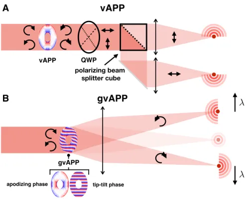
vAPP
QWP vAPP polarizing beam splitter cubeFigure 1. Sketches of (A) the vector Apodizing Phase Plate (vAPP) and (B) the grating vAPP (gvAPP). Leakage by the QWP and polarizer will imprint a copy of the one coronagraphic PSF onto the other. This sets much stricter tolerances on these elements as the bright side of the one coronagraphic PSF will leak into the dark hole of the other. This leakage is stronger than leakage by the non-coronagraphic PSF. Leakage by the QWP is not only dependent on retardance o↵sets ( ), but also on fast axis orientation o↵sets ( ✓) w.r.t. polarizer. The total leakage (IQW P) (ignoring an irrelevant cross term) is given by:
IQW P ⇡ sin(
1
2 )
2+ sin( ✓)2. (2)
Leakage by the polarizer is simply given by the extinction ratio.
The vAPP and QWP can be optically contacted to form one optic, the polarizer can be further down-stream in the system. It is critical to ensure that the QWP maps the circular polarization states (with the imprinted phase patterns) to the linear polarization states that are separated by the polarizer, i.e. the QWP and polarizer need to be carefully aligned.
Requirements on the components of the 180 vAPP for a raw contrast of < 10 5 are given in Table 1.
The leakage requirements are determined by the ratio of the intensities at the IWA between respectively the coronagraphic PSF and non-coronagraphic PSF (for the HWP), and the opposite coronagraphic PSFs (for the QWP and polarizer). Equation 1andEquation 2translate this to the requirements on the retardance and fast axis orientation. The requirements of the 360 vAPP are slightly relaxed due to the (generally) larger IWA and therefore the more favourable ratio between the intensities of the coronagraphic and non-coronagraphic PSF. Requirements on the QWP and polarizer are absent as the double-grating symmetric vAPPs do not need these components.
Fig. 1. Schematic of two different vAPP implementations. Top: The vAPP, where PSFs with dark zones on opposite sides and opposite polarization states are separated using a quarter-wave plate and a polarizing beam-splitter. Bottom: The gvAPP where polarization states are separated by adding a phase ramp (= polarization grating) to the vAPP phase pattern, which generates opposite tilt for light with left- and right-circular polarization, adapted from [19].
vAPP for unpolarized light would present a low-intensity (∼ 1%) non-coronagraphic PSF at the location of the coronagraphic PSF. Moreover, for linearly polarized light this PSF would even be coherent with the coronagraphic PSF. Both reduce the contrast at the smallest separations. Third, the gvAPP has two dark holes on opposite side, increasing the search space by a factor two. This comes at the cost of a factor of two in exoplanet throughput, with half of the light being imaged at the bright side of one of the two coronagraphic PSFs. We note that for unknown companions this factor is the same when using an APP, having to rotate the APP to image both sides. Advantages of the two vAPP dark holes are that they have the same AO performance, such that one PSF can be used as a reference for post processing [21], and that the antisymmetric PSF is beneficiary for wavefront sensing [22]. Moreover, the direct-write system is capable of writing much finer structures (∼ 1𝜇m) compared to diamond turning (∼ 50𝜇m) and has the ability to write discontinuous phase steps. These properties enable a tremendously increased phase pattern complexity that can be used for holography [23] and manufacture more optimal phase patterns [24].
A third kind of vAPP is the double-grating vAPP (dgvAPP). The dgvAPP combines a gvAPP with a second polarization grating on a separate substrate [24]. This second grating is identical to the gvAPP grating and has the opposite effect, diffracting both the main beams back on axis. Polarization leakage of the liquid-crystal film on the first substrate is diffracted outside
the dark zone by the second grating, reducing the total on-axis polarization leakage by multiple orders of magnitude. Because both beams are recombined, the phase pattern needs to produce a 360◦ dark zone, which requires more extreme patterns, increases the inner boundary of the dark zone, and generally reduces the PSF-core throughput. However, the planet light is also recombined in the dark zone, so the throughput is a factor 2 higher. A common property is that all vAPP implementations is that they operate over 100% bandwidth with extremely high efficiency (> 96%).
The development of multiple types of vAPP coronagraphs coincided with progress in many other areas of the vAPP coronagraph, including vAPP design, the improvement of the focal-plane wavefront capabilities, and the manufacturing of gvAPPs for multiple high-contrast imaging instruments. In this paper we review this progress. In section 2, we detail the design considerations and we provide the first complete step-by-step description of the vAPP design process, including adding holograms, or wavelength selective behavior. We describe the impact of a standard gvAPP design on observation and data reduction in section 3, followed by an overview of the manufactured and planned vAPPs in section 4. This includes their properties, details of the commissioning, performance, and for some, their first scientific results. In section 5 we discuss the current status and provide suggestions for future upgrades.
2. Design of a gvAPP
The design of a gvAPP starts with the optimization of an APP phase pattern. The goal of the optimization is to null the stellar PSF in the dark zone to by orders of magnitude with respect to the PSF core, e.g 105. We define the contrast as this ratio of flux in the dark zone divided by the
flux in the PSF core and it depends on the focal plane coordinates, see Fig. 2. Light has to be diffracted from the stellar PSF core to null the dark zone, reducing the intrinsic Strehl ratio of the star. We define the Strehl ratio as the summed flux of the non-coronagraphic stellar PSF core in an aperture divided by the summed flux of energy in the coronagraphic stellar PSF core using the same aperture. In simulation without noise this aperture has a diameter of one pixel, and for all other applications it is common to use a diameter of ∼ 1.4𝜆/𝐷 [3]. Destructively interfering the star light in the dark zone results in constructive interference of the light on the opposite side of the PSF. A reduction of the stellar Strehl ratio is unwanted, as the Strehl ratio of the companion PSF is affected in the same way. Therefore, the optimization simultaneously maximizes the Strehl ratio of the stellar PSF, while minimizing the flux inside the dark zone. This optimization problem is highly non-linear in the complex phase exponential. Consequently, first attempts at calculating APP patterns did not aim to find the optimal solution, their aim was to find solutions that are close. These attempts used phase iteration techniques [7, 25] or a modified Gerchberg-Saxton (GS) algorithm [26] and were moderately successful. They have shown that these methods can produce a dark zone of any shape with extreme contrasts (< 10−10) [27], yet their Strehl ratios are low for small inner working angles. Another set of solutions were generated by adapting the global optimization algorithms for shaped-pupil coronagraphs to include phase [28]. This algorithm produces APPs with regions containing several discrete phases and sharp transitions in between these regions. This algorithm was improved to yield globally optimal solutions with unity amplitude across the pupil, smooth phase patterns for 180◦and D-shaped dark zones, and 0-𝜋 solutions for 360◦dark zones [29]. As this last algorithm allows both phase and amplitude modulation in the pupil, this proves empirically that APPs are the globally optimal solutions for pupil-plane coronagraphs.
2.1. Dark zone considerations
The globally optimal solutions are critical to ensure a high exoplanet yield. However, it is not the full story. As shown in [29], there is a trade-off between inner working angle (IWA), outer working angle (OWA), contrast, and Strehl. The definitions of the four properties can be found in Fig. 2.
IWA OWA IWA
OWA
Figure 2. The pupil-plane and focal-plane geometry considered in this work. Any spiders holding up the central obscuration are neglected. Left The pupil of the telescope. Middle A D-shaped dark zone. Right An annular dark zone.
tilt each iterations (as in the case of the modified Gerchberg-Saxton algorithm) or by removing tip-tilt from the
mode basis used for optimization. As we optimize electric field and have no access to the optimization algorithm
directly, we instead have to introduce a constraint in the optimization problem to counteract this behavior.
The simplest and most e↵ective way is to enforce that the PSF reaches its maximum at (0, 0). In this way
moving the PSF is not allowed. This constraint can be approximated as a linear constraint by enforcing that
the absolute value of both the real and imaginary part of the electric field may not be larger than its value at
(0, 0). A quadratic constraint on the PSF itself would be best, but takes more computation time. Typically the
PSF moves perpendicular to the dark zone shape, so we only need to enforce this in the direction opposite to
the dark zone, starting at (0, 0) itself. The optimization problem now reads
maximize
X(x),Y (x)
R
{E(0)}
(28)
subject to R
{E(k)} + I {E(k)} <
p
S
expected· 10
c(29)
R
{E(k)}
I
{E(k)} <
p
S
expected· 10
c(30)
R
{E(k)} + I {E(k)} <
p
S
expected· 10
c(31)
R
{E(k)}
I
{E(k)} <
p
S
expected· 10
c(32)
E(k) =
F{A(x)(X(x) + iY (x))}
(33)
X
2(x) + Y
2(x)
18x
(34)
R
{E(k)} R {E(0)} 8k
(35)
R
{E(k)} R {E(0)} 8k
(36)
I
{E(k)} R {E(0)} 8k
(37)
I
{E(k)} R {E(0)} 8k.
(38)
We use this final optimization problem for the rest of this paper.
3. CASE STUDIES
3.1 D-shaped dark zones
In this section we consider a D-shaped dark zone. This dark zone is parameterized by their inner-working angle,
outer-working angle and contrast. For the aperture we take a circular aperture with a central obscuration. This
geometry is shown graphically in Figure 2. In the following sections we vary the dark-zone parameters and use
the Strehl ratio as a metric. In Figure 3 we show some solutions with their parameters along with the resulting
PSF.
D
IWA OWA
Strehl Contrast
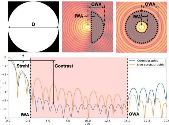
Fig. 2. Definitions of the dark zone properties. Top left: The pupil of the telescope. Top middle: A D-shaped dark zone (log10scale). Top right: An annular dark zone
(log10scale). Bottom: PSF slice of a non-coronagraphic and coronagraphic design
(annular). Adapted from Por 2017 [29].
For focal-plane coronagraphs, the IWA is defined as the smallest angular separation at which the total energy throughput of an off-axis source reaches 50% of the maximum throughput [3]. For pupil-plane coronagraphs this can be adapted to the smallest angular separation where the planet throughput reaches 50% of the maximum throughput in the region where the contrast reaches the target contrast. Equivalently, the OWA is defined as the largest angular separation where the planet throughput still reaches 50% of the maximum throughput in the region where the contrast reaches the target contrast. A good choice of these parameters can be different for every planetary system, observing conditions, wavelength, telescope design and instrument performance. This becomes clear by using a metric that defines a planet detection given instrument limits. In Ruane et al. 2018 [3], the integration time Δ𝑡 that is required for a 1𝜎 detection is given by
Δ𝑡 ∝ " 𝜂𝑠+ Í 𝑛𝑎𝑛 𝜂2𝑝− 𝑏2/𝜖2 # , (1)
where 𝜂𝑠fraction of available star light detected at the planet location, 𝜂𝑝fraction of available
planet light detected, and 𝜖 is the planet-to-star flux ratio. The factor 𝑎𝑛represents noise factors
like the background or detector noise such that 𝜎𝑛2= 𝑎𝑛𝑁★, with 𝑁★the total signal from star
in photo-electrons. In the same way 𝜎speck= 𝑏𝑁★, which represents the speckle noise. In this
framework, 𝜂𝑝 is directly proportional to the vAPP Strehl and the contrast is given by 𝜂𝑠/𝜂𝑝.
We do not minimize Δ𝑡 with vAPP optimization due to several complicating factors. However, we can use this equation to explore the impact of design choices. Here we outline some of the
considerations when choosing these parameters.
1. Strehl:The Strehl ratio of a vAPP design impacts the planet throughput for the full field of view. In the case of the photon noise limit, Eq. 1 becomes Δ𝑡 = 𝜂𝑠/𝜂
2
𝑝, demonstrating that Strehl
greatly impacts the integration time that results in a 1𝜎 detection. The gvAPP already has the disadvantage of reducing the planet throughput by a factor of 2, so keeping the Strehl high is crucial for good performance. The definition of a high Strehl is somewhat arbitrary given the impact of the shape of the telescope pupil, AO performance and presence of other noise sources. Therefore, we use the Strehl mostly for a trade-off between the other dark zone properties.
2. Contrast: For ground-based high-contrast imaging systems, the intrinsic contrast of a coronagraph is almost never reached. AO residuals and non-common path errors result in quasi-static speckles that limit the performance. In addition, atmospheric jet streams create a wind-driven halo, as the temporal lag between the application of the wavefront correction and the evolving turbulence [30]. Designing a gvAPP with an intrinsic contrast much lower than the expected raw contrast does not yield the optimal performance. This is clear from Eq. 1, where planet is not detected in the presence of speckle noise if 𝜂𝑝 < 𝑏/𝜖 (negative integration time),
independent of 𝜂𝑠. Yet, removing bright PSF structures by creating a dark zone reduces speckle
pinning, i.e. speckles that are spatially confined to secondary maxima in the diffraction limited PSF [31]. Taking into account speckle pinning, it can be argued that a design contrast lower than the expected AO-limited contrast does result in an improved performance, although that has not been studied in detail. For inner working angles > 2.0𝜆/𝐷 and a central obscuration lower than 30%, a design contrast of 10−4results in Strehl ratios higher than 70% [29]. This design contrast is already significantly lower than the raw contrast of extreme AO systems. Another consideration is that constant contrast in the dark zone will yield the highest Strehl, although the changes in Strehl are minor for lower contrasts further out. These considerations lead to the conclusion that a more optimal gvAPP design has a contrast that decreases gradually with the estimated AO residuals and becomes constant at a point where other noise factors take over, such as detector noise or background noise (∼ 10−6). An example of such a design contrast is shown in Fig. 2. In this case, the vAPP design contrast can be determined by AO simulations and verified with end-to-end simulations of the performance.
3. IWA:All indirect detection methods for exoplanets (e.g. transit, radial-velocity, astrometry), show that there is a huge fraction of planets that is currently out of reach for direct imaging. While these methods are biased to find these close-in planets, it shows that a small IWA is a critical to find new worlds with direct imaging. However, the Strehl ratio is also very dependent on the IWA. For 10−6contrast, an OWA of 8 𝜆/𝐷, and a central obscuration of 10% changing the IWA from 2.05 to 1.75 𝜆/𝐷 reduces the Strehl from 60% to 20% [29]. Furthermore, the gain of a smaller inner working angle is usually limited. Uncorrected low-order aberrations, both atmospheric or non-common path, reduce the performance at the smallest separations for ground-based telescopes.
4. OWA:The outer working angle has limited impact on the Strehl of APP designs, while the dark zone area increases with the OWA squared. The non-coronagraphic PSF contains only a small fraction of the energy at larger separations, so increasing the contrast in this region results in a small decrease in Strehl as well. In these regions the SNR of the exoplanets is not dominated by the contrast, however. Further out, techniques like ADI are more effective in removing speckles, the wind-driven halo and PSF structures. Thermal background in the near- and mid-infrared (𝜆 > 2µm) or detector noise start to dominate the SNR, e.g. [32]. It is therefore unnecessary for most applications to create a gvAPP with a OWA > 20𝜆/𝐷.
There is no general design that works for any telescope or wavelength range. All gvAPP designs are different because the optimal phase pattern depends on the telescope aperture and properties like the AO performance and background noise. It is therefore advisable to perform a grid search to find the trade-offs between IWA, OWA, contrast at the IWA and the slope of the contrast as
function of radius. An example grid could be the IWA between 1.8 and 2.3 𝜆/𝐷 in steps of 0.1, the OWA between 12 and 20 𝜆/𝐷 in steps of 1, the log(contrast) between 10−3.5and 10−5 in steps of 0.5, and a slope between 0.25 and 0.5 log(contrast) per 𝜆/𝐷 in steps of 0.05.
Another consideration is the dark zone shape itself. A gvAPP with D-shaped dark zones provides phase solutions with higher Strehl ratios compared to 180 degree dark zones with identical inner working angles [29]. This difference in Strehl increases for smaller inner working angles (< 2.5𝜆/𝐷), which is why the D-shape is used in most gvAPPs. The impact of the D-shape on observing is discussed in section 3.1. An interesting trade-off exists for planet detection at larger IWAs (> 3𝜆/𝐷). Beyond this IWA threshold, the designs with an annular dark zone will have a Strehl ratio that can be competitive with D-shaped dark zones. While the Strehl ratio of designs with annular dark zones are still significantly lower, dgvAPPs with annular dark zones have twice the planet throughput compared to a gvAPP. The origin of this factor two is that half of the planet light is imaged on the bright side of the coronagraphic PSF for a gvAPP. The trade-off between D-shaped and annular dark zones is highly dependent on the telescope pupil, as a central obscuration size and spider thickness greatly impact the Strehl of annular dark zone designs. We note that comparing Strehl ratios with a factor two correction factor for planet throughput and the same contrast levels does not necessarily select the best of the two. There are other factors that are more difficult to add to this trade-off. For example, a dgvAPP will not have wavelength smearing due to grating diffraction, companions will be inside the dark zone for all parallactic angles, post-processing is different, and a gvAPP requires a larger field of view. Because factors like these are difficult to quantify, we did not attempt a general trade-off study. So far, only one dgvAPP has been installed on the large binocular telescope (LBT). The pupil of the LBT is favourable with a central obscuration ratio of ∼ 11% and thin spiders that were not included in the design. Moreover, a vAPP with an annular dark zone was installed on the William Herschel Telescope (WHT), which was designed for an off-axis 1-m pupil without central obscuration and spiders.
2.2. Optimization of the APP design
The optimization of the APP starts with a pupil definition. Existing HCI instruments usually have a pupil camera where the pupil can be measured or have their own mask to define the pupil. Extreme caution is warranted when defining the pupil, as the maxima and minima of the phase pattern will be located near the pupil edges. An error in pupil definition leads to a stark reduction in vAPP performance. For this reason we define an APP pupil, which is the undersized version of the true pupil to accommodate alignment errors, definition errors, and pupil movement. Drastic undersizing increases the IWA, negatively impacts Strehl with thicker spiders and a larger central obscuration ratio, and reduces throughput by removing effective telescope area. Therefore, this balance results in an undersizing of the instrument pupil by 2-5%, depending on the amplitude of the expected pupil movement and the alignment tolerances, and in coordination with the instrument team. In addition, it can be beneficial to change the orientation of the dark zones depending on the pupil shape. Spiders add narrow diffraction structures that locally enhance the PSF intensity. A D-shaped dark zone can, depending on the orientation with respect to the pupil, overlap with one or more spider diffraction structures. Removing these structures leads to a decrease in Strehl, so if there is freedom to choose the dark zone orientation the straight edge should be oriented parallel to two spiders. Residual atmospheric dispersion, detector ghosting effects, the FOV of an IFS or the orientation of a slit or image slicer can limit this design freedom. For a given set of APP parameters and a pupil definition, we use the optimization solver, Gurobi Optimizer [33], to calculate the optimal solution. Computer memory and run time limitations limit the APP phase pattern to 100 × 100 pixels and a dark zone up to 14 𝜆/𝐷. For N pixels in the pupil plane, the optimization problem scales as N2in computer memory and N3.5in run time. These scaling laws also hold true for pixels in the focal plane for the OWA. Hence, it is
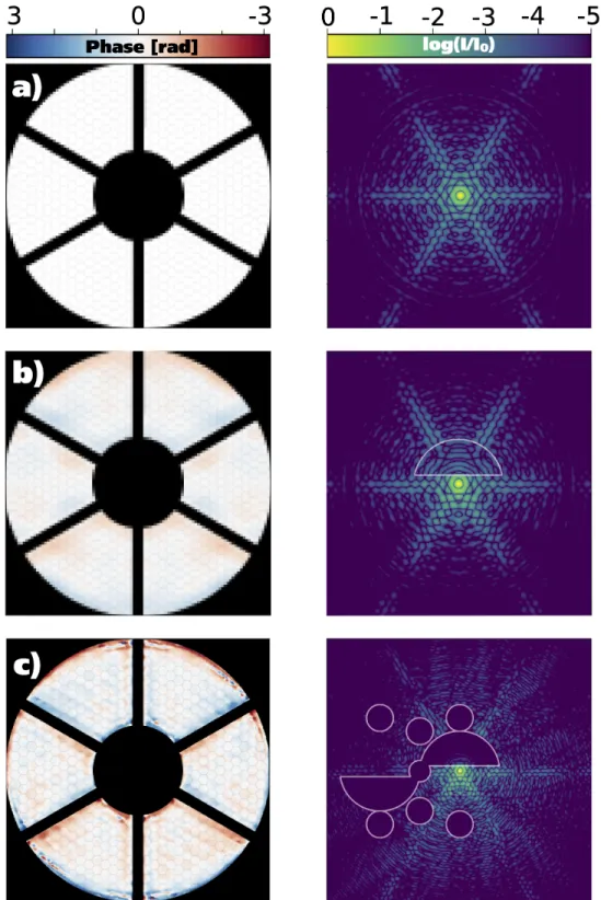
Fig. 3. Optimization of an APP pattern, showing the phase pattern (left) and corre-sponding PSF (right). a) The low-resolution input pupil for the global optimizer and the corresponding PSF. b) Output of the global optimizer for a lower contrast (10−3) and a smaller dark zone, indicated by the white lines. c) High-resolution APP design created using the Gerchberg-Saxton algorithm on the Fourier-scaled global optimal APP design. Additional dark zones have been added for the opposite coronagraphic PSF, the leakage PSF and additional holograms.
not possible to calculate the APP design at the full resolution that is used in the direct-write system, which is on the order of a 1000×1000 pixels. We therefore adopt a two-stage approach for finding the vAPP phase pattern. First we find the optimal APP phase pattern for a downscaled version of the APP pupil. If necessary we decrease the OWA to the 14 𝜆/𝐷 limit set by the computer memory. This downscaled version also does not contain additional dark zones for the coronagraphic PSF with opposite circular polarization or dark zones that minimize crosstalk with the leakage term or additional holograms. In section 2.3 the use of these additional dark zones and holograms is explained. Secondly, we upscale this low-resolution APP phase pattern design with Fourier upsampling [34] and use this solution as a prior for the second stage. This second stage adds all dark zones and corrects any errors made during the upsampling of the low-resolution phase pattern. We use a modified Gerchberg-Saxton (GS) algorithm [35] for this stage. This algorithm does not guarantee an optimal solution like the global optimizer does. However, with the starting point already quite close the optimal solution, the GS algorithm is likely to converge before unacceptable Strehl losses occur.
An example for resulting phase patterns after the first and second stage are shown in Fig. 3. In practice, we find that limiting the design contrast during the first stage of optimization often increases the Strehl of the final design. Typically, for a final design contrast < 10−4the design contrast during the first stage should be between 10−2and 10−3.5to recover a new solution with the highest Strehl. Both optimization stages are implemented in HCIPy [36] and an example of vAPP optimization using only GS can be found in its documentation1.
2.3. Adding functionality with holograms
Enabled only by the accurate and high-resolution of the direct-write process and the liquid-crystal properties, it is possible to add capabilities to all types of vAPPs. Here we will discuss two capabilities, focal-plane wavefront sensing (FPWFS) and reference spots for astrometry and photometry. Both capabilities have solutions based on holograms. We define holograms as PSF copies imaged off-axis, which can be biased with a wavefront aberration. In essence, the vAPP PSFs are also holograms. Combining multiple holograms into a single phase screen is possible through multiplexing wavefronts into a single phase screen, as described in [37–39]. A multiplexed phase screen directs light to multiple holograms, each with a different PSF. These holograms can be added anywhere in the focal plane up to the Nyquist limit, with any bias, and with any amplitude mixing ratio. Due to circular-polarization splitting, adding a holographic copy at a certain position in the focal plane will necessarily also add a hologram with opposite bias at the location mirrored in the optical axis. These properties of holograms make them very diverse and easily adapted for FPWFS and reference spots. A natural extension is to generate multiple coronagraphic PSFs per polarization state. For example, it is possible to position two coronagraphic PSFs for one polarization such that they precisely overlap with the two coronagraphic PSFs of the opposite polarization state. The advantage is that the otherwise polarized coronagraphic PSFs now become unpolarized [40]. This has benefits for including polarimetry and/or focal-plane wavefront sensing with the vAPP. One important downside is that multiplexing many holograms results in significant crosstalk. Crosstalk adds PSFs at locations that are the vector-addition of the individual gratings and multiples thereof.
2.3.1. Photometric and astrometric reference spots
For accurate photometry of a companion the vAPP already has an advantage compared to focal-plane coronagraphs. The coronagraphic PSFs themselves provide a photometric reference, given that the two PSFs are not saturated. Otherwise the leakage PSF can serve as photometric reference if it is not too affected by speckles. However, it does have a different spectrum due to the wavelength dependence of the diffraction efficiency. A solution is an unbiased reference
spot, which is a copy of the non-coronagraphic PSF. Multiplexing unbiased wavefronts with the vAPP results in reference PSFs that can be used both for photometry and astrometry. For other coronagraphs, such spots have been generated using the deformable mirror or static phase screen. A full summary of these efforts can be found in Bos (2020) [41] and references therein. Moreover, the vector speckle grid that is proposed in Bos (2020) [41] produces speckles that are effectively incoherent with the underlying halo, which greatly improve the photometric and astrometric accuracy. By multiplexing the vAPP with two holograms with opposite phase modulation on the opposite polarization states, this vector speckle grid is easily implemented in the vAPP coronagraph. Astrometry with a vector speckle grid could provide astrometric solutions with a precision of < 0.01𝜆/𝐷 [41], however this has not yet been tested on-sky.
2.3.2. Focal-plane wavefront sensing
Adding a bias wavefront to holograms changes their sensitivity to the incoming wavefront. Holographic modal focal-plane wavefront sensing is possible because of these variations [27]. FPWFS is critical to remove non-common path aberrations (NCPA), aberrations from optics after the AO system, which are therefore unseen by the AO wavefront sensor. An example of a focal-plane wavefront sensor is the coronagraphic modal wavefront sensor (cMWS) [23, 38], which provides simultaneous coronagraphic imaging and focal-plane wavefront sensing with the science point-spread function. The cMWS creates multiple holograms, each biased with a different wavefront mode drawn from a suitable basis set. The normalized difference between the PSF copies with opposite circular-polarization state responds linearly to the corresponding aberration mode present in the input wavefront. The main advantage of this wavefront sensor is that the monitoring the Strehl ratios of the holograms and the wavefront reconstruction are straightforward and can be done at high speeds and with the actual science camera, independent from the dark hole(s). Moreover, no modulation of the wavefront is required. Multiplexing holograms removes light from the coronagraphic PSF, and for efficient wavefront sensing each mode takes away ∼ 1% of Strehl, on top of the already lower vAPP Strehl. The trade-off between modal coverage, sensitivity and Strehl is difficult to optimize, as it is a priori unclear how much the selected wavefront modes contribute to speckles. The cMWS has successfully been tested with the Leiden exoplanet instrument (LEXI) [23], and in lab demonstrations of Magellan/MagAO-X [42].
Another method for FPWFS is an adaptation of phase diversity (PD) [43]. Where classical PD requires an in-focus and out-of-focus image, phase diversity holograms are biased with defocus of opposite amplitude, similar to the cMWS with a larger bias. This larger bias results in an increase in modes that can be reconstructed, while decreasing the average intensity of the hologram. So compared to the cMWS, a larger fraction of the incoming light is diffracted to the PD holograms, e.g. 10% instead of 1%. This FPWFS method was implemented in the Subaru/SCExAO [44], Magellan/MagAO-X [45] and HiCIBaS instruments. A different implementation of PD is described in Por (2016) [46], directly reconstructing the focal-plane electric field in the dark zone. Coronagraphic PSF copies are created with each a unique probe in the dark zone, making use of the pairwise nature of the holograms [27]. The unaltered science PSF is still available, providing the same advantages as the cMWS, but adding the capability to sense all modes corresponding to the dark zone.
Interestingly, the coronagraphic PSFs themselves can also be designed to encode wavefront information in the bright field by including a pupil-plane amplitude asymmetry. The added advantage of the vAPP is that there are two coronagraphic PSFs, with opposite bright fields that cover all of the spatial frequencies. This reduces the number of modes that can otherwise not be measured by one coronagraphic PSF [47]. We refer to such vAPP designs as Asymmetric Pupil vAPPs (APvAPPs), and was successfully implemented by Bos et al. (2019) [22]. They show that if the pupil is asymmetric, both odd and even modes can be recovered from the
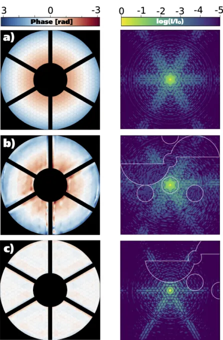
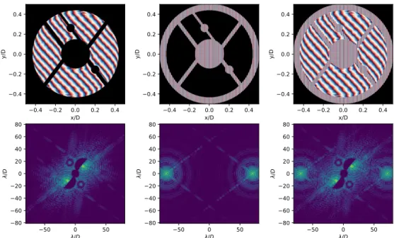
Fig. 4. Updates of the holographic phase patterns to minimize crosstalk and light scattering into the dark zones. a) An unaltered phase diversity hologram with a defocus of 0.87 radian RMS. b) The updated PD hologram with suppressed diffraction structures in all dark zones, calculated using the Gerchberg-Saxton (GS) algorithm. c) Same as b), only without defocus to create a photometric or astrometric reference hologram. Each hologram has displaced dark zones. This displacement corresponds to the relative location of the hologram with respect to the dark zones of the coronagraphic PSF after multiplexing the phase patterns.
1
2
3
4
1
2
3
4
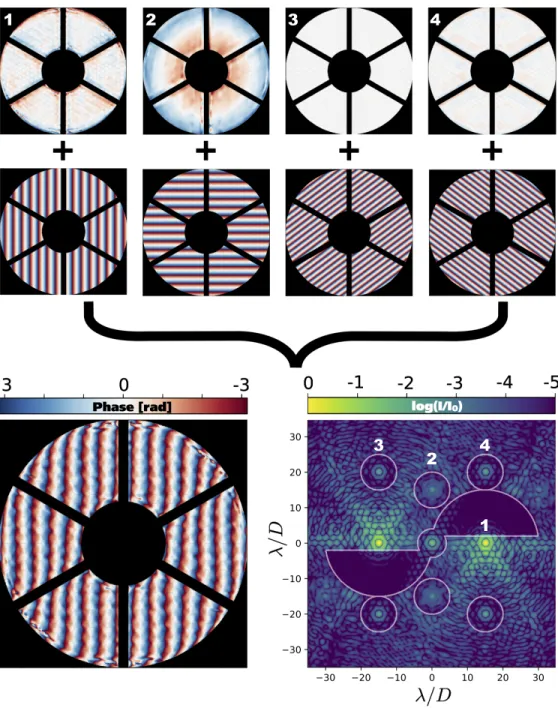
Fig. 5. Creation of a gvAPP phase pattern by multiplexing the APP design (1) with the three holograms. Hologram 2 is defocused and could be used for focal-plane wavefront sensing. Hologram 3 and 4 are unaberrated and are located in a square grid at the grating frequency for astrometric referencing. Additional iterations with GS have cleared the dark zone of second order effects caused by multiplexing. The PSF is calculated assuming unpolarized light and a polarization leakage of 1%.
coronagraphic PSFs only. Earlier versions of an asymmetric pupil wavefront sensor [48] could not be combined with a coronagraph. A non-linear model-based wavefront sensing algorithm was proposed by [22] and is limited, due to computational considerations, to the first ∼ 100 Zernike modes, yet it showed nearly an order of magnitude improvement in contrast between 2 and 4 𝜆/𝐷 with the internal source, and on-sky the gain was a factor of 2. Spatial linear dark field control (LDFC) [42, 49] is also a very powerful combination with the APvAPP. LDFC empirically derives a linear relationship between DM actuation and focal-plane intensity response in the bright field, allowing it to control a larger number of modes. As LDFC can only drive back the wavefront to a reference state, it requires an initial calibration by non-linear model-based wavefront sensing algorithm, making both methods complimentary. LDFC uses the linear response to wavefront aberrations in the bright side of the vAPP PSF to reconstruct the wavefront. For Magellan/MagAO-X, simulations have shown that LDFC is capable of correcting the full dark zone using 400 modes [42]. Recently, LDFC in combination with an APvAPP was installed and tested using Subaru/SCExAO [50]. An on-sky demonstration followed soon after [51]. By multiplexing two coronagraphic PSFs per polarization state, each of these PSFs designed with a different pupil-plane amplitude asymmetry, it is also possible to design APvAPPs that can measure both pupil-plane phase and amplitude modes simultaneously [40]. The possibility of adding photometric, astrometric, and wavefront sensing capabilities to the vAPP make it a unique and diverse coronagraph. Exploring these techniques for a more integrated approach to building high-contrast imaging systems shall lead to a better performance at the systems level.
2.3.3. Implementation into vAPP designs
Adding holograms by multiplexing phase patterns does not result in an optimal combination. Crosstalk between modes and the vAPP PSF will decrease the contrast in the vAPP coronagraphic dark zones. Moreover, the crosstalk will change the response of the holograms. Minimizing this crosstalk is implemented by changing the vAPP PSF, the modes and optimizing after multiplexing. First, the coronagraphic PSF can be suppressed at the locations of the holograms, such that interference is minimized. Additional dark zones can be added during the upscaling of the APP design. Second, the modes can be adapted to also have a reduced intensity at the location of the APP dark zone. These dark zones can be added using the GS algorithm, as is shown in Fig. 4. All modified holograms, including the coronagraphic vAPP hologram, can then be combined by multiplexing. Third, the crosstalk in the vAPP dark zones caused by the multiplexing can be removed by applying an additional round of GS. The combined result is shown in Fig. 5. Every time GS is applied, it has a minor impact on the Strehl of the coronagraphic PSF. The final cleaning of the dark zone could impact the performance of holographic wavefront sensors, though we estimate that this effect is minimal, as no significant deviation from expected performance was found in [42]
2.4. Additional design choices
So far we have focused on the design of the vAPP phase pattern. However, there are additional choices regarding the vAPP optic that are independent of the phase pattern. We will highlight two design choices that impact the manufacturing complexity and the wavelength dependent performance of the vAPP.
2.4.1. The grating mask
As discussed in section 2.2, the pupil definition is critical for the performance of the vAPP. During manufacturing it is therefore standard to add a physical binary amplitude mask to the assembly that is aligned with sub-micron accuracy with the phase pattern. These amplitude masks and their alignment add significant complexity and cost to the vAPP optic. Especially for lab demonstration projects that often require multiple phase patterns, it is not cost effective
Fig. 6. Top left: Phase of a grating-vAPP for an undersized pupil of the Subaru Telescope. An amplitude mask for the pupil is shown in black. Bottom left: Logarithmic plot of the PSF of the grating-vAPP, showing two coronagraphic PSFs for opposite handedness of circularly polarized light. The grating-vAPP was simulated to be a perfect half-wave retarder, so no leakage is present. Center: The grating mask (top) and resulting PSF (bottom) that will be used as an amplitude mask. The grating has 90 periods across the diameter of the pupil. Right: The phase and PSF of the grating-vAPP combined with the grating mask. The incoming light has a pupil of radius 0.45 (black) and the light is separated in a grating mask component and a grating-vAPP component. A small misalignment of the pupil does not affect the coronagraphic PSF, relaxing alignment tolerances. Adapted from Doelman et al. 2017 [44].
to use these amplitude masks. Separate metal laser-cut masks can provide a cheap solution at the cost of reduced alignment accuracy. We note that it is not necessary to absorb or reflect the light at the pupil plane. A different solution is to diffract the light outside of the field of view of the coronagraphic PSFs. Diffracting the light that is not falling onto the coronagraphic phase pattern to outside the FOV requires a patterned high-frequency polarization grating outside of the pupil, e.g. beyond the outer diameter, inside the spiders, and within the central obscuration. This grating should have a different orientation and frequency than the grating of the gvAPP. A simple spatial filter in an intermediate focal plane can remove the light outside the pupil. We call this concept the “grating mask”. This concept is described in detail in Doelman et al. 2017 [44], and a reworded version is added here for clarity. An example of the gvAPP with a grating mask is shown in Fig. 6. Critical for the workings of a PG as amplitude mask is that the tilt is applied
locally, as the phase is accumulated inside the liquid-crystal layer [52]. This is unlike a regular grating where the interference between the full grating results in the diffraction orders. Adding a mask only outside the pupil does not significantly alter the coronagraphic PSF. It does, however, change the leakage term from the PSF of the undersized vAPP pupil to the PSF of the telescope or instrument pupil.
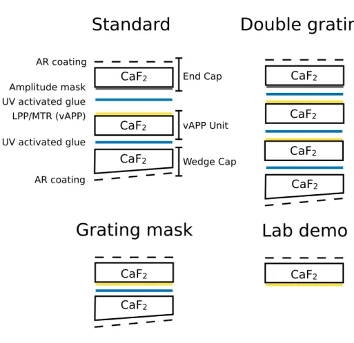
How the grating mask reduces the complexity of the vAPP optic can be seen in Fig. 7. With a grating mask the first substrate is no longer necessary, removing a glue layer as well. Moreover, the lab demo vAPPs can be manufactured without any additional substrates. While their phase
CaF
2CaF
2CaF
2CaF
2CaF
2CaF
2CaF
2 AR coatingCaF
2CaF
2CaF
2 Amplitude mask UV activated glue LPP/MTR (vAPP) AR coating UV activated glue End Cap vAPP Unit Wedge CapStandard
Double grating
Grating mask
Lab demo
Fig. 7. Various substrate designs for vAPP manufacturing.
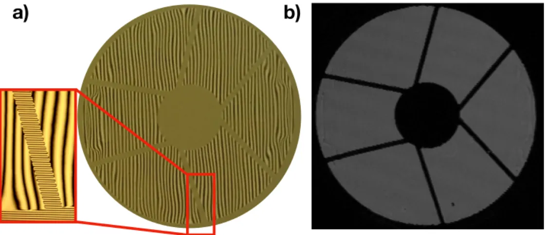
patterns and pupils can be extremely complex, only homogeneous illumination is necessary for them to work as expected. We note that an end cap would make them more durable and less easy to damage. For lab testing a 1 cm grating mask was produced with 8 pixels of 8.75 micron per period. The pupil is a simplified version of the Nancy Grace Roman Space Telescope and was chosen for the thin spiders and complex pupil design. The full mask between crossed polarizers is shown on the left in Fig. 8 in addition to a microscopic image which shows a spider with the grating pattern. The width of the spider is a few times the grating period, yet this does not affect the performance of the grating mask. The right panel of Fig. 8 shows the reimaged pupil when a field stop is added to the focal plane. The light outside the simplified RST pupil, which is diffracted by the grating, is blocked and does not appear in the reimaged pupil.
When applied in a real high-contrast imaging system, two things need to be considered. First, one has to be careful where the diffracted light from outside the pupil is directed to. The diffracted light can scatter back onto the detector by reflections inside the instrument if not blocked. Because the direction of the PG is a free design parameter, the reflections can be directed to non-reflective parts with prior knowledge of the instrument layout. Second, a few percent of the light that would be normally blocked by an amplitude mask would end up on the science camera due to polarization leakage. This polarization leakage is always non-zero for a deviation in retardance from half-wave. The influence of the polarization leakage will be small when the coronagraphic
b)
a)
Fig. 8. a) Photograph of the vAPP with a simplified RST pupil between crossed
polarizers, manufactured for testing the grating mask. The zoomed in microscope image shows the high-frequency grating used for the grating mask that is not captured by the normal camera. b) Reimaged pupil with a field stop inserted in the focal plane. The field stop removes the diffracted light from outside the pupil defined by the grating mask. Even spiders with a width of a few times the grating period are removed extremely well.
PSFs are have enough spatial separation from the leakage. This separation is also a free parameter and is set by the frequency of the grating of the coronagraphic phase pattern. In addition, the pupil defined by the grating mask will be undersized a few % compared to the telescope pupil, so the amount of light that is diffracted by the grating mask is limited.
Overall, the grating mask is a cheap alternative for amplitude masks and alleviates the problems that come with aligning an amplitude mask with the phase pattern.
2.4.2. Wavelength selective multi-twist retarders
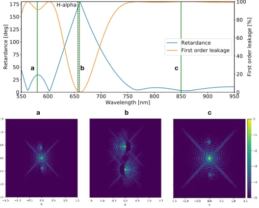
Another option for the vAPP involves the tuning of the retardance in a non-standard way. For most applications the retardance is tuned to be close to half-wave over the full bandwidth of an instrument [18,21] to maximize the efficiency. However, by changing the liquid-crystal recipe one can, in principle, make the retardance follow any continuous curve as function of wavelength [53]. We note that this is possible because the fast-axis orientation and retardance of the devices are decoupled. One specific application of a liquid-crystal recipe is the “wavelength-selective coronagraph” [44]. Here we include a short summary of this work. A wavelength-selective coronagraph has rapidly changing efficiencies, where the retardance switches between intervals of 180 degrees as function of wavelength. A retardance of zero or a full wave results in a zero efficiency, such that the light traveling through the coronagraph does not acquire geometric phase. The coronagraph is effectively switched off at those wavelengths, while it is switched on in the range where the retardance is close to half-wave. This technology has been demonstrated for RGB lenses [54]. An example for the vAPP coronagraph is shown in Fig. 9. The retardance is close to 180 degrees for H𝛼 and close to zero for smaller than 600 nm and larger than 750 nm. The light outside the H𝛼 spectral band can be used by a wavefront sensor, enabling wavefront sensing close to the science bandwidth with optimal efficiency. In addition, the wavefront sensor can be placed after the coronagraph to minimize non-common path aberrations. This requires a simple focal plane mask that separates the central term from the coronagraphic PSFs, aided by some spectral filters to minimize spectral cross-talk.
a b c
a b c
Fig. 9. Top: Simulated retardance (blue) and first order leakage (orange) as a function of wavelength for a 3-layered MTR. The total thickness is 20.7 micron and it was optimized to have 0 retardance everywhere except for a 10 nm band around H𝛼 wavelength (656.28 nm), where the retardance is close to 180 degrees. Bottom: The simulated PSFs of a grating-vAPP with the retardance profile shown above. The green lines in the top figure correspond to the wavelengths of the bottom panel. At wavelengths shorter than H𝛼 the leakage term dominates and almost no coronagraphic PSF can be seen (a). This is the same for wavelengths larger than 750 nm (c). Around H𝛼 the leakage term disappears and the gvAPP operates as normal (b).
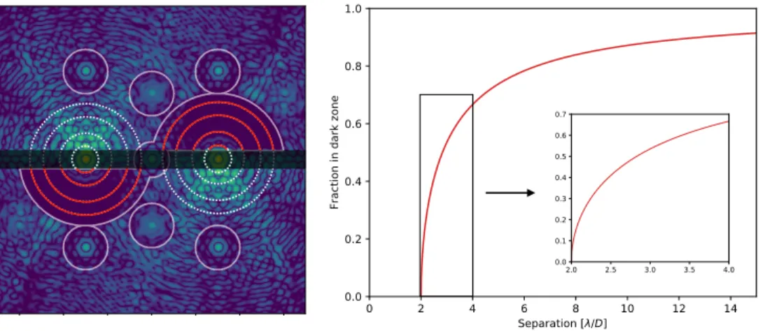
Fig. 10. Planets rotating in the dark zone in pupil-stabilized mode are not always in the dark zone. Left: Fraction of a circle (white) that is in the dark zone (red). Right: The same fraction as function of separation for an inner working angle of 2𝜆/𝐷.
3. Observing and data reduction
The gvAPP can be described as a simple coronagraph, as it is only a single pupil-plane optic that suppresses the diffraction halo. However, there are two differences between other coronagraphs that make both observing and data reduction much less straightforward, i.e. the D-shaped dark zone and the grating. For the D-shape dark zone of a gvAPP the dark zones do not cover 360 degrees, which takes away a larger fraction for closer-in orbits caused by sky-rotation. This has to taken into account for planning observations and in the data reduction process. In addition, the grating can smear the planet PSF over multiple pixels in the grating direction, reducing signal-to-noise and the effectiveness of observing techniques like angular differential imaging (ADI) [55].
3.1. Influence of the D-shaped dark zone
The D-shaped dark zone provides phase solutions that have much higher Strehl ratios for similar smaller inner working angles than a 180 degree dark zone, while providing a similar total area. We note that the term inner working angle is somewhat misleading here. It is correct that the D-shaped and 180 degree dark zone designs can detect a planet down to the same separation, yet the amount of time it is in the dark zone for pupil tracking mode is very different. For a 180 degree dark zone the coverage is a full 360 degrees, while a bar is missing for the D-shaped dark zone, which takes away a larger fraction for closer-in orbits. The fraction of a circle, 𝐹𝐷 𝐻, with
radius 𝑟 that is inside a dark zone with an inner working angle IWA is given by 𝐹𝐷 𝐻 =
𝜋− 2 arcsin (IWA/𝑟) 𝜋
. (2)
This fraction is also shown in Fig. 10 for a typical gvAPP design. On-sky the rotation speed can change dramatically near Zenith, and the position in the dark zone depends on the local sidereal time at the observatory. Therefore, observations with the gvAPP should be carefully planned if a known target is observed. Planning does not help with detecting unknown objects where certain areas around the star will have more noise due to the sky-rotation placing objects in the bar between dark zones.
can be predicted. To this end, we created a preliminary version of an observation preparation tool in python, which can be found on Github 2. The goal of this tool is to predict the locations of known companions and provide information on when it is in the dark zone to help determine observation strategies. The current version has an internal library that contains the information of a few operational gvAPPs, such that a simple query returns the predicted locations of companions in a PSF image. The code needs the instrument name, target name, the companion position angle and separation, and the observation times. Wavelength scaling has not been implemented yet. The core of the observation tool is based on Astropy [56], which is used to retrieve object information and coordinate transformations.
3.2. Influence of wavelength smearing
The grating of the gvAPP is an elegant solution to separate the polarization leakage from the coronagraphic PSFs. It does, however, represent a challenge for the data reduction. For narrow-band data it displaces the two coronagraphic PSFs which need to be recombined after centering them separately. This is similar for data taken with an integral field spectrograph (IFS), except the instrument provides simultaneous multi-wavelength observations. For each wavelength, the stellar PSF and companion PSF will have shifted and also needs to be recombined. This can be characterized, especially if there are no optical distortions in the IFS such that the displacement from the grating is linear. Wavelength smearing is likely to reduce the astrometric accuracy in addition to make object spectra more sensitive to the lenslet flat. For larger bandwidths the wavelength smearing introduces more problems. The light of the planet is smeared over many pixels, resulting in an increase in camera noise and a larger sensitivity to speckle noise. In addition, the planet PSF rotates around the stellar PSF for every wavelength, which is a different location on the detector for every wavelength. In the derotated rest frame of the stellar PSF the orientation of the elongation changes in time, such that ADI techniques are less effective. Collapsing the PSF in the grating direction before derotation might solve this problem, but this does not remove the sensitivity to speckle and camera noise.
The classical vAPP, which separates the two polarization states with a Wollaston prism, would not have these issues caused by the grating [14]. However, they would be limited by polarization leakage at the smallest separations for large bandwidths. A double-grating vAPP is also not affected by the grating, it is not limited by polarization leakage, and does have full 360 degree FOV at the cost of a larger inner working angle. Combining these two techniques creates a solution for the wavelength smearing and large inner working angle. This combination then requires a polarizing beam splitter, like a Wollaston prism, to separate the two polarization states of a double-grating vAPP with D-shaped dark zones [19].
3.3. Data reduction
From the complications of data reduction caused by the D-shape of the dark zone and the grating, it is clear that gvAPP data can not simply be reduced with commonly-used data reduction pipelines like the Vortex Image Processing package [57] or PynPoint [58, 59]. These pipelines include different data reduction algorithms that have been developed for data taken without coronagraphs or with focal-plane coronagraphs. In both situations the stellar PSF is not separated and the search space is 360 degrees. However, with a relatively simple adaptation it is possible reshape gvAPP data in a way that these pipelines can be used. We create a window for each coronagraphic PSF and combine them into a single new data frame that is centered on both PSF cores. An example is shown in Fig. 11. This method also works for IFS data if the windows change location with wavelength, but does not solve the wavelength smearing for large bandwidths. In addition, it does not make use of the fact that both coronagraphic PSFs are aberrated by the same
Fig. 11. Method of recombining both coronagraphic PSFs such that the data can be processed using conventional data reduction techniques.
wavefront aberration. The rotate subtract algorithm, suggested by [21], provides an additional contrast gain by using this symmetry. An improved version of this algorithm does not simply subtract the average PSF but uses principal component analysis [60] to create a PSF library using one coronagraphic PSF and optimally removing these components from the other PSF. Another technique that is likely well suited for gvAPP data is the Temporal Reference Analysis for Exoplanets (TRAP) algorithm [61]. TRAP creates a data driven model of the temporal behavior of the systematics using reference pixels, which can also be the pixels at the other coronagraphic PSF. Moreover, this algorithm assumes a PSF model that can include wavelength smearing, which is a significant problem for the gvAPP. Therefore, TRAP presents an exciting opportunity to improve the gvAPP data reduction.
4. The world of vAPP
Over the last decade the vAPP has been installed in 7 instruments on 6 telescopes, and will be installed in two instruments on the Extremely Large Telescope (ELT). The success of the vAPP can be explained by two of its properties: simplicity and adaptability. Each vAPP is unique and fully optimized for the system it is implemented in, both in wavelength coverage as phase design, while only a single optic needs to be installed. The vAPPs cover almost an order of magnitude in bandwidth, i.e. 0.55-5 𝜇m, provide multiple ways of focal-plane wavefront sensing, and provide
pìÄ~êì= p`bñ^l biq= jf`^al biq= jbqfp j~ÖÉää~å= j~Ö^lJu j~ÖÉää~å= j~Ö^l teq= ibuf i_q=
ijfoÅ~ã ijfoÅ~ãi_q=
c^pqJ`^ojbk= eá`f_~p siq= bofp ^ÅíáîÉ mÜ~ëÉW aÉëáÖå `çããáëëáçåáåÖ oÉãçîÉÇ
Fig. 12. Overview and status of the vAPP coronagraphs around the world.
photometric/astrometric capabilities. First, we will provide an overview of the different properties and locations of the vAPPs. Then, we will shortly describe the unique capabilities of each vAPP. 4.1. The vAPP: a global view
High-contrast imaging systems are now part of most 8m-class telescopes. The vAPP has benefited from the enormous growth in the number of high-contrast imaging systems. A global view of the vAPP coronagraphs is shown in Fig. 12. The vAPPs are operational in both the Northern and Southern hemisphere. For each vAPP, we show the phase pattern and the simulated PSF. In addition, we display the project status, indicated by the color of the marker on the map. As of 2020, the vAPP has been tested in two former instruments, is operational in four instruments and will be installed on three more instruments. A summary of most properties of all vAPPs are presented in Table 1.
T able 1. Proper ties of the vAPP coronag raphs. FPWFS tec hniq ues: 1 = AP -WFS [22 ], 2 = cMW S [27 ,38 ,42 ], 3 = PD [43 ,45 ]. T elescope Ins tr ument T ype Ins t. 𝜆 MTR Contras t IW A O W A S trehl FPWFS [ 𝜇 m] [ 𝜆 / 𝐷 ] [ 𝜆 / 𝐷 ] [%] Mag ellan MagA O/Clio gvAPP 2x180 2015 2-5 3 10 − 5 2.0 7 39.8 -WHT LEXI vAPP 360 2017 0.6-0.8 1 10 − 4 2.5 6 57.2 2 Subar u SCExA O/ gvAPP 2x180 2018 1-2.5 3 10 − 5 2.1 11 49.2 1+3 CHARIS FC HiCIBaS gvAPP 2x180 2018 0.83-0.88 1 10 − 6 2.1 8.5 28.8 2+3 Mag ellan MagA O-X gvAPP 2x180 2018 0.55-0.9 3 10 − 5 2.1 15 40.7 1+2+3 LBT LMIRcam gvAPP 2x180 2018 2-5 3 10 − 5 1.8 15 52.6 3 LBT LMIRcam/ dgvAPP 360 2018 2-5 3 10 − 5 2.7 15 42.0 -ALES VL T ERIS gvAPP 2x180 2022 2-5 3 10 − 5 2.2 15 50.9 1 EL T METIS gvAPP 2x180 2028 2.9-5.3 3 10 − 5 2.5 20 63.8 1 EL T MIC ADO gvAPP 2x180 2026 1-2.5 3 10 − 5 2.6 20 68.8
-0.5 0.6 0.7 0.8 1.0 1.25 1.75 2.5 3.4 5.0 [ m] 0 2 4 6 8 10 12 14 Zero-order leakage [%] B H I Y J H K L M HiCIBaS LBT MagAO-X SCExAO LEXI
Fig. 13. Zero-order leakage as a function of wavelength for different liquid-crystal recipes, colored by instrument.
Another important property of the vAPP is the polarization leakage as function of wavelength. The design of the liquid-crystal recipes aims to minimize polarization leakage over the full bandwidth and are given in Table 1. For small bandwidths (< 15%), the liquid-crystal design can be kept simple with only single layer with zero twist. Larger bandwidths require multiple layers, each with different thickness and twist, to form a multi-twist retarder (MTR). In general, if the bandwidth is between 15 − 40%, a double-layered recipe, i.e. a 2TR, can have a polarization leakage < 3% for the full bandwidth. Similar performance can be reached with a 3TR for bandwidths up to 100%.
When a specific design is chosen, the manufacturing process is tuned to generate a liquid-crystal film with a measured retardance and polarization leakage that mimics the theoretical as closely as possible. The manufactured test films are polarization gratings (PGs), such that it is easy to measure the zero-order leakage using transmission measurements. When a recipe is perfected, the vAPP is manufactured using this recipe. Measuring the zero-order leakage of the final optic can be cumbersome with the small angular separations between the main beams and the leakage, caused by the large grating periods of a gvAPP. Therefore, the leakage measurement of a representative PG is used. These polarization leakages of five different recipes, representative of 5 different instruments and wavelength ranges, is shown in Fig. 13. All presented recipes have <6% leakage over their required bandwidth. Together, they span the almost the full visible and near-infrared (0.55-5 𝜇m). Interestingly, we currently cover this range with three standardized recipes that have good performance in their respective bandwidths. The same data is presented in log-scale in Fig. 14. We added the estimated performance of the double-grating vAPP that is installed in the LBT, by multiplying the single-grating curve with itself. We note that no direct measurement of its performance exists.
While the leakage measurements are representative, the actual vAPPs can have different performances. Lab conditions during manufacturing, like temperature and humidity, can generate differences between liquid-crystal films for identical recipes. Characterizing the actual polarization leakage of a vAPP can then be done after installation or in a high-contrast imaging setup. Moreover, all vAPPs with identical wavelength coverage will have different polarization
0.5 0.6 0.7 0.8 1.0 1.25 1.75 2.5 3.4 5.0 [ m] 10 6 10 5 10 4 10 3 10 2 10 1 100 Zero-order leakage B H I Y J H K L M HiCIBaS LBT MagAO-X SCExAO LEXI LBT dg
Fig. 14. Same as Fig. 13, but on log-scale and an additional estimate of the LBT double-grating vAPP.
leakages as function of wavelength. These differences can be up to 2% for a specific wavelength, but the impact on the average is minimal. Most likely, it is merely a shift of the maxima and minima as function of wavelength.
4.2. The vAPP: individual properties
A large diversity exists between vAPPs, in designs, design goals, additional functionality, and the instruments that use them. We will provide a summary of design trade-offs, unique properties, historical details, notable results, and references to more detailed papers of each vAPP.
4.2.1. Magellan/MagAO/Clio
The first operational broadband gvAPP was installed in 2015 in the MagAO/Clio instru-ment [62, 63] at the 6.5-m Magellan Clay telescope. The gvAPP has a dark zone between 2-7 𝜆/D and operates between 2 to 5 micron, with a polarization leakage less than 3% over this bandwidth. A detailed description of the design, manufacturing and on-sky performance can be found in Otten et al. (2017) [21]. Being the first gvAPP to be commissioned, it was a technology demonstrator with the additional goal to use it as a science-grade component. To demonstrate the performance, Otten et al. observed a bright A-type star with an 𝐿0-band magnitude between 0 and 1. Characterization of the leakage term and the PSF showed that the gvAPP was performing as expected. A new method of data reduction, subtracting the opposite rotated coronagraphic PSF, yielded an improvement in contrast of 1.46 magnitudes, i.e. a factor 3.8, at 3.5𝜆/D. The performance of the gvAPP for this observation was better than the best reported performance in literature of coronagraphs at other systems at this small angle. We note that the method of calculating the noise is necessarily different between the contrast curves reported in literature, as noted in Jensen-Clem et al. (2017) [64]. The method of noise calculation in Otten et al. (2017) [21] does not take into account azimuthally correlated speckle noise caused by non-common path aberrations, pointing jitter, and thermal variations. For a gvAPP it is especially difficult to properly estimate the speckle noise at the smallest separations due to the limited amount of photometric apertures that fit in the D-shaped dark zones. A better comparison