HAL Id: hal-01878544
https://hal-univ-lemans.archives-ouvertes.fr/hal-01878544
Submitted on 14 Jun 2019
HAL is a multi-disciplinary open access
archive for the deposit and dissemination of
sci-entific research documents, whether they are
pub-lished or not. The documents may come from
teaching and research institutions in France or
abroad, or from public or private research centers.
L’archive ouverte pluridisciplinaire HAL, est
destinée au dépôt et à la diffusion de documents
scientifiques de niveau recherche, publiés ou non,
émanant des établissements d’enseignement et de
recherche français ou étrangers, des laboratoires
publics ou privés.
Artificial buzzing lips and brass instruments:
Experimental results
Joël Gilbert, Sylvie Ponthus, Jean-François Petiot
To cite this version:
Joël Gilbert, Sylvie Ponthus, Jean-François Petiot. Artificial buzzing lips and brass instruments:
Experimental results. Journal of the Acoustical Society of America, Acoustical Society of America,
1998, 104 (3), pp.1627-1632. �10.1121/1.424375�. �hal-01878544�
Artificial buzzing lips and brass instruments: Experimental
results
Joe¨l Gilbert and Sylvie Ponthus
Institut d’Acoustique et de Me´canique de l’Universite´ du Maine, Laboratoire d’Acoustique—UMR CNRS 6613, Avenue Olivier Messiaen, 72085 Le Mans Cedex 9, France
Jean-Franc¸ois Petiot
Institut de Recherche en Cyberne´tique de Nantes, UMR CNRS 6597—Equipe CMAO Productique, 1 rue de la Noe¨, BP 92101, 44321 Nantes Cedex 3, France
Experimental results of a special artificial trombone player are presented: A mechanical device is a substitute for the musician. Wind instruments, and particularly the brass, are self-sustained oscillators. The oscillations are induced by a mechanical oscillator ~the lips of the player! acting as a valve which modulates the flow. Measured mechanical parameters of the artificial buzzing lips for different ‘‘embouchures of the player’’ are presented, and analyzed in connection with the played frequencies obtained for the same ‘‘embouchures.’’ The results are obtained with two resonator systems ~a mouthpiece alone and a trombone with its mouthpiece!.
PACS numbers: 43.75.Fg@WJS#
INTRODUCTION
Oscillations of wind instruments, and particularly lip-driven wind instruments ~the brass!, are driven by self-sustained oscillations of an air flow. These oscillations are induced by a mechanical oscillator ~the lips of the player!, acting as a valve which modulates the flow. The destabiliza-tion of the mechanical element is the result of a complex aeroelastic coupling among~1! the lips, ~2! the air flow en-tering the instrument as a result of the static overpressure in the mouth of the musician, and~3! the resonant acoustic field in the instrument itself. The brass instruments have been ex-tensively studied ~see, for example, Backus, 1976; Pratt
et al., 1977; Elliot et al., 1982; Causse et al., 1984!. A global
study including the player behavior has been proposed by Elliot and Bowsher~1982!. In the last 10 years, time-domain simulations based on this kind of model have been proposed
~Strong and Dudley, 1993; Dietz and Amir, 1995; Adachi
and Sato, 1996; Rodet and Vergez, 1996; Juin, 1996; Msal-lam et al., 1997!. Due to the essential nonlinearity of the governing equations describing the mechanical behavior of the lips coupled with the air flow entering the instrument, it is important to focus our attention on this part of the system. Some experimental results focused on the human lip oscilla-tions have been obtained: Martin~1942!; Elliot and Bowsher
~1982!; Saneyoshi et al. ~1987!; Yoshikawa ~1995!; Bailliet
et al. ~1995!; Chen and Weinreich ~1996!; Copley and
Strong ~1996!. One of the major difficulties of this kind of experimental study on vibrating lips is the human player. In order to avoid this major difficulty, we have decided to de-velop an artificial mouth for brass using artificial buzzing lips.
Previous studies on reed musical instruments ~Backus, 1963; Wilson and Beavers, 1974; Meynial, 1987; Gilbert, 1991; Idogawa et al., 1993; Gazengel, 1994; Dalmont et al., 1995! have demonstrated the usefulness of a mechanical
de-vice as a substitute for the musician. This substitution allows stable mouth controls and makes it possible to take extensive measurements during stable playing conditions and to com-pare these with characteristic features of the instrument. We will present here comparisons of the playing frequency near the threshold of oscillations, the acoustical passive resonance frequency of the instrument and the mechanical passive reso-nance frequency of the lips. After a first artificial mouth for brass instruments ~Gilbert and Petiot, 1997a, b! was devel-oped in order to measure the effect of nonlinear propagation in the instrument ~Beauchamp, 1980; Hirschberg et al., 1996!, a second one ~Piau, 1997! has been constructed with improved control of the embouchure, and the latter has been used in the experiments described in this paper.
The present paper is divided into three parts. After this brief Introduction, we present the experimental setups in Sec. I: the artificial mouth setup, the input impedance measure-ment, and the artificial lips’ mechanical characterization are described successively. Different frequencies are obtained from these setups ~Sec. II!: the acoustical resonance fre-quency ~Fres! from the input impedance measurement, the lips’ eigenfrequencies ~Flip! from the mechanical character-ization, and the played frequencies ~Fplay! by playing the instrument with the artificial mouth. By controlling the ‘‘em-bouchure’’ of the artificial mouth, the lips’ frequencies and the played frequencies are slightly modified. The measure-ments are reported twice: first with a mouthpiece alone, sec-ond with the entire trombone including its mouthpiece. Fi-nally the experimental results are analyzed.
I. EXPERIMENTAL SETUPS AND PROCEDURES A. Artificial mouth and buzzing lips
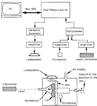
The artificial mouth ~Fig. 1! consists of a hermetically sealed box~volume 1500 cm3! fed by a high-pressure ~5-bar maximum! air supply. The mouth pressure in the box is
con-trolled by a pressure regulator. A 1 m long tube of 1 cm diameter connects the regulating valve to the artificial mouth. The ‘‘artificial lip’’ is a latex tube filled with water. The lip is 150 mm long, with a diameter of 16 mm, and a wall thickness of 0.6 mm. It is constrained by an ‘‘artificial jaw’’ consisting of a plate with a circular hole of 2 cm diameter
~Fig. 1!. The lip is pressed by the mouthpiece against the
‘‘jaw.’’ There are two mechanical control parameters for the embouchure: a control of the lip tension, and a control of the position of the mouthpiece relative to the lip. Thus the ‘‘em-bouchure,’’ the way the mouthpiece and lips interact, is con-trolled by the intrinsic parameters of the lips such as the tension of the latex tubes, the mass of water inside, and the position of the mouthpiece relative to the lips. The last is the only parameter used to vary the embouchure for experiments presented in Sec. II.
There are minor differences with respect to the first ver-sion of the artificial mouth described in Gilbert and Petiot
~1997a, b!. The mechanical system of the embouchure is
moved from the front to the back of the mouth; the mouth-piece is clamped and remains fixed. Therefore it is possible to replace one brass instrument with another without pertur-bation of the embouchure. In the experiments described here, to have a mechanical system as simple as possible, only one latex lip is installed, the other being replaced by a solid plate. The artificial mouth has a realistic playing performance, as judged by listening to the sound produced by the system. Notice that such a single lip drive has already been used by Gokhstein~1981! for observations on human lip oscillations.
B. Resonator input impedance 1. Input impedance measurement
The air resonator system, a mouthpiece alone or a trom-bone with its mouthpiece, is characterized by its input im-pedance ~complex quotient of the acoustical pressure and volume velocity in the input of the resonator in forced oscil-lations!. The input impedances are measured by the appara-tus described in Dalmont and Bruneau~1991!. The apparatus is a simple plane support for three microphones ~including one microphone acting as source! and the object to be mea-sured. In practice, an adaptator needs to be custom-made to fix the object to the support. Within the measuring probe an
electrostatic transducer~1/2-in electrostatic microphone car-tridge B&K! is used as a source and two electret micro-phones~electret microphone cartridges, Sennheiser KE4! are used as receivers. The two receivers are placed in the same plane as the emitter on either side and diametrically opposite each other. Notice that for our application we only use one of the two receiving microphones. The second one is useful when measurements of the first helical mode are performed
~Dalmont and Bruneau, 1991!. Our impedance
measure-ments are done below the first cut-off frequency, so that the plane-wave propagation approximation is accurate.
The impedance measurements shown below are made with a harmonic source. The transfer function ~microphone signal over excitation signal! is obtained by a dual-phase-lock-in technique. The frequency range of the swept sine is typically 20–1000 Hz. Before the measurements we use a method of calibration based on preliminary measurements with a set of closed cylindrical tubes @for further details, see Dalmont and Bruneau~1991!#.
2. Results
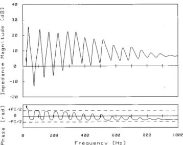
Figure 2 shows the measured input impedance of the trombone ~Courtois model 149! with its mouthpiece ~Bach model Megatone 61/2 AM!. The impedance curve is
compa-rable with, among others, the experimental results of Elliot and Bowsher~1982!. The parameters ~frequency, quality fac-tor, magnitude! of the eight first resonances are given in Table I. Moreover the input impedance of the trombone mouthpiece alone has been measured. As expected, the mouthpiece has only one resonance frequency ~frequency corresponding to a magnitude maximum and a zero phase of the input impedance!: the resonance frequency is Fm
5545.6 Hz, and the quality factor of this resonance is 19.9.
We will use in our further discussion the following reso-nance frequencies for comparison with the other frequencies: the resonance frequency Fm of the mouthpiece (Fm
FIG. 1. The artificial mouth for brass instruments.
FIG. 2. The measured input impedance of the trombone ~Courtois model 149! with its mouthpiece ~Bach model Megatone 61/2AM!. The value of the impedance magnitude~decibel representation! is expressed in units ofrc/S ~the characteristic impedance of the air in the pressure-volume velocity
anal-ogy, S is the input cross-sectional area of the mouthpiece!. The value of the impedance phase is expressed in radian.
5545.6 Hz), and the resonance frequencies number 3, 4, 5
of the trombone (Ft35169.1 Hz, Ft45228.2 Hz, Ft5
5290.8 Hz!.
C. Artificial lip mechanical response 1. Mechanical response measurement
The aim of the experimental setup described below is to allow a mechanical characterization of the embouchure~the lip and its boundary conditions imposed by the position of the mouthpiece!. The mechanical response of the lip is ob-tained by simultaneous measurement of lip vibration~using a laser vibrometer Polytec OFV 3000! and the acoustic pres-sure in the mouth behind the lip and the jaw~using an elec-tret microphone cartridge, Sennheiser KE4!. The lip is ex-cited in forced oscillation by a sound source~a compression loudspeaker driver, JBL model TRS001!. The mechanical response ~vibrometer displacement signal over mouth pres-sure signal! is obtained by means of a dual-phase-lock-in technique~Fig. 3!. The frequency range of the swept sine is typically 50 to 500 Hz.
The source is positioned behind the lip; we assume that the pressure there is locally uniform, and representative of
the force applied to the lip. Because of the construction of the artificial mouth and to keep the embouchure constant during the measurement, the mouthpiece remains in position during the measurement. The frequency range used is below the resonance frequency of the mouthpiece (Fm
5545.6 Hz). We assume that the latter does not influence
too much the mechanical response measurement of the lip. To avoid degradation of the vibrometer signal through ab-sorption in the transparent box wall, the laser is focused on the lip through the mouthpiece tube. The vibrometer detects the velocity of the vibration of the lip along the axis of the laser, which is the axis of the mouthpiece in our case ~lon-gitudinal vibration!. In order to derive the mechanical re-sponse as defined below, we need the lip displacement. Thus after the experiments the velocity measurements are divided by jv to obtain the displacement results.
2. Results
The mechanical response of the lip is the response of the longitudinal lip displacement ~in the flow direction! to the driving pressure as a function of the frequency. On the curve presented in Fig. 4 we choose the lip frequency Flip ~210 Hz! as the frequency where we have the most pronounced resonance ~highest magnitude! with a phase equal to 2p/2. Incidentally, a phase equal to 2p/2 at the resonance corre-sponds to the ‘‘outward beating reed’’ behavior according to the model of Elliot and Bowsher ~1982!.
Testing the artificial mouth, we have observed that the most efficient parameter to control the embouchure is the position of the mouthpiece relative to the lip. This parameter controlling the geometric boundary conditions of the lip is more effective and accurate than the control parameter of the lip tension. Mechanical responses of the lip have been mea-sured for different settings of the embouchure. For an in-crease of the static pressure of the mouthpiece on the lips, we observe an increase of the lip frequency Flip from 120 to 260
TABLE I. Frequency~Hz!, quality factor ~dimensionless!, and magnitude
~dB! of the eight first resonances of the trombone ~Courtois model 149! with
its mouthpiece~Bach model Megatone 61/2AM!.
Resonance
number Frequency~Hz! Quality factor Magnitude~dB!
1 38.1 8.4 25.5 2 111.3 18.1 23.9 3 169.1 19.8 22.2 4 228.2 24.6 21.6 5 290.8 24.9 22.4 6 343.3 34.6 22.1 7 399.2 31.1 18.4 8 458.1 28.0 17.5
FIG. 3. The mechanical response measurement setup.
FIG. 4. A measured mechanical response of the lips. The value of the mechanical response magnitude~decibel representation! is expressed in ar-bitrary units. The value of the phase is expressed in radian.
Hz. These frequencies are compared with playing frequen-cies following an experimental procedure described in the next section.
II. COMPARISON OF TUBE RESONANCE, LIP RESONANCE, AND PLAYING FREQUENCIES A. Experimental procedure
Once the mouthpiece is fixed in position, for a particular setting of the embouchure, the experimental procedure is car-ried out as follows:
~1! We generate a stable sound with the mouthpiece
alone. This is done by a slow increase of the supply pressure until stable buzzing of the lip is achieved. We measure the corresponding fundamental oscillation frequency~the played frequency Fplay1corresponding to the mouthpiece alone!.
~2! We place the trombone on the mouthpiece. We
re-peat the procedure described in~1! and we measure the fun-damental oscillation frequency~the played frequency Fplay2
corresponding to the trombone and the mouthpiece!.
~3! The air supply is switched off, the trombone is
dis-mantled, and the source of sound ~the loudspeaker! is switched on. We perform the mechanical response measure-ment on the lips. The mechanical resonance frequency of the lip is measured~the lip frequency Flip!.
~4! We repeat the operation ~1! to ensure that the
em-bouchure has remained constant during the entire procedure. We then modify the embouchure and repeat the complete procedure.
Notice that we have performed the mechanical response measurement of the lip with the air supply switched off to have a direct characterization of the mechanical behavior of the embouchure, assumed uncoupled to the acoustic resona-tor in this case. To do the same kind of measurement with nonzero mean flow could be an interesting and useful exten-sion of the results described in this paper. In this way, we could see how the coupling between the mechanical oscilla-tor~the lip! and the acoustical oscillator ~the mouthpiece, for example! due to the airflow at the lip orifice, modifies the eigenfrequencies of the coupled system, and consequently modifies the Flip estimated from the vibrometer measure-ment of lip vibration.
B. Results and discussion
We have measured three frequencies for each embou-chure: the played frequencies Fplay1and Fplay2, and the lip
frequency Flip. It is useful to present the played frequencies as functions of the lip frequency. The results with two kinds of acoustical resonators are presented, respectively: the mouthpiece alone~Fig. 5!, and the trombone with its mouth-piece~Fig. 6!. Please note again that we have simplified the artificial lips using only one lip: the second half of the mouthpiece entrance, corresponding to the removed lip, is closed with a plate.
Figure 5 plots the frequency of the self-excited sound Fplay against the lip eigenfrequency Flip. As expected from the case of buzzing lips, the sound frequency increases with the lip frequency. Some of the results are, however, unex-pected. The playing frequency is always below the resonance
frequency of the mouthpiece and always above the lip fre-quency. At first sight this is inconsistent with results of the classic one mass model: according to the ‘‘inward beating reed’’ behavior, the playing frequency should be below both the resonance frequency and the lip frequency. According to the ‘‘outward beating reed’’ behavior, the playing frequency should be above both the resonance frequency and the lip frequency~Fletcher, 1979!. Moreover we found with the ar-tificial mouth a second oscillation regime ~see in Fig. 5 the bifurcation between the two regimes near the frequency lip value of 210 Hz! which is not predicted by a single mass model. This might be a second vibrating mode of the lip. Such a second lip mode could be a second longitudinal mode observed in the measured mechanical response~see the sec-ond mechanical resonance around 80 Hz in Fig. 4!. It could also be a transverse mode invisible in our measurements be-cause of the particular position of the vibrometer which mea-sures the lip vibration only along the axis of the mouthpiece.
FIG. 5. The played frequency Fplay1 as a function of the lip frequency Flip. The resonator is the mouthpiece alone~Bach model Megatone 61/2AM!, its
resonance frequency is Fm5545.6 Hz.
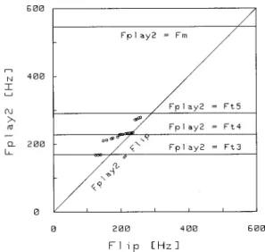
FIG. 6. The played frequency Fplay2 as a function of the lip frequency Flip. The resonator is the trombone ~Courtois model 149! with its mouthpiece
~Bach model Megatone 61/2AM!, the useful resonance frequencies are
At the moment such hypotheses remain unconfirmed. In view of the existence of these two buzzing regimes, using a two mass model for the lip becomes attractive.
During the experimental procedure, for each embou-chure we have placed the trombone on the mouthpiece. For a variation of the lip frequency from 120 to 260 Hz, we have obtained three notes corresponding to the resonance frequen-cies number 3, 4, and 5 of the trombone. The three notes played are F3, Bflat3, and D4. Figure 6 plots the frequency of the self-sustained sound Fplay against the lip eigenfre-quency Flip with the resonance frequencies number 3, 4, and 5 of the trombone~the horizontal straight lines in the figure!. The bisection line where Fplay is equal to Flip is also drawn. Between adjacent resonance modes, frequency gaps that rep-resent the mode transitions between two adjacent notes are found. But in each resonance mode, the playing frequency Fplay does not take a constant value. Instead, there is a fre-quency range of Fplay where a self-oscillation is possible and where Fplay gradually ascends with an increase in Flip. This behavior of the artificial mouth is quite similar to that observed for a human trombone player. Is it possible to draw a conclusion about the lip model from these experimental results? Again, the results are not compatible with the basic one-mass model: the played frequencies are sometimes be-low and sometimes above the resonance frequencies.
Even if these experimental results on artificial buzzing lip cannot be directly linked with the simplified one-mass or two-mass models, it is interesting to perform a qualitative comparison with previous experimental results obtained for real brass players. As observed by Chen and Weinreich
~1996!, brass players are able to pull the pitch of the played
note both well above and well below the resonant frequency of the instrument ~bend technique!; we have observed the same kind of results with the artificial buzzing lip coupled with a trombone~Fig. 6!. This confirms that the simple one-mass model ~outward or inward beating! does not suffice. But we should note that a one-mass model such as that pro-posed by Elliot and Bowsher ~1982! can predict both an inward and an outward behavior: As remarked by Campbell and Greated~1987!, the two forces acting on the mechanical oscillator with one degree of freedom have opposite signs, so by making one or the other force dominate, the desired type of behavior can be obtained. The two forces are the pressure difference between the mouth and the mouthpiece and the Bernoulli pressure at the lip orifice. In the same way, the one-mass model of Elliot and Bowsher is compatible with the observations of Yoshikawa~1995! of the transition from the outward-striking oscillation in low modes to the upward-striking oscillations in high modes. On the other hand, the experimental results obtained with the artificial buzzing lip coupled with a mouthpiece alone ~Fig. 5! seem not to be easily compatible with a one-mass model, because of the existence of two different buzzing regimes. In this case, to describe the essential features of the oscillatory behavior of the lips, it seems that we need a two-mass model similar to that used to describe vocal fold motion~Ishizaka and Flana-gan, 1972; Pelorson et al., 1994! or snoring ~Auregan and Depollier, 1995!. Direct visualizations have already high-lighted two degrees of freedom~Martin, 1942; Jorno, 1996;
Copley and Strong, 1996!, and Gokhshtein ~1981!, using a subtle and interesting visualization technique, observed that in the low register the human lips execute a wavelike motion. Moreover this two-mass model is attractive from the view-point of the trombone player: it could explain the ability to generate self-sustained lip oscillations over a large range of frequencies without the mouthpiece and the instrument ~the ‘‘buzz technique’’!. We are convinced that additional experi-ments on other artificial mouths in progress~Vergez and Ro-det, 1997; Cullen et al., 1998! will in the near future provide a better understanding of the buzzing lips behavior. Inci-dently such experiments will supply parameter values for the time simulations of brass instruments.
ACKNOWLEDGMENTS
We would like to aknowledge D. M. Campbell, J. Cullen, J. P. Dalmont, A. Hirschberg, and R. Msallam for helpful discussions about acoustics of brass instruments and for comments on this work.
Adachi, S., and Sato, M.~1996!. ‘‘Trumpet sound simulation using a two-dimensional lip vibration model,’’ J. Acoust. Soc. Am. 99, 1200–1209. Aure´gan, Y., and Depollier, C.~1995!. ‘‘Snoring: linear stability analysis
and in-vitro experiments,’’ J. Sound Vib. 188, 39–54.
Backus, J.~1963!. ‘‘Small-vibration theory of the clarinet,’’ J. Acoust. Soc. Am. 35, 305–313.
Backus, J.~1976!. ‘‘Input impedance curves for the brass instruments,’’ J. Acoust. Soc. Am. 60, 470–480.
Bailliet, H., Pelorson, X., Richardson, B., and Lallouache, T.~1995!. ‘‘Lip vibration and pressure recordings during french horn playing,’’ in
Pro-ceedings of the International Symposium on Musical Acoustics, Dourdan,
France~Socie´te´ Franc¸aise d’Acoustique, Paris!, pp. 23–28.
Beauchamp, J. W.~1980!. ‘‘Analysis of simultaneous mouthpiece and out-put waveforms,’’ Audio Engineering Society, preprint No. 1626, pp. 1– 11.
Campbell, D. M., and Greated, C.~1987!. The Musician’s Guide to
Acous-tics~Dent, London!.
Causse´, R., Kergomard, J., and Lurton, X. ~1984!. ‘‘Input impedance of brass musical instruments—Comparison between experiment and numeri-cal models,’’ J. Acoust. Soc. Am. 75, 241–254.
Chen, F. C., and Weinreich, G.~1996!. ‘‘Nature of the lip reed,’’ J. Acoust. Soc. Am. 99, 1227–1233.
Copley, D. C., and Strong, W. J. ~1996!. ‘‘A stroboscopic study of lip vibrations in a trombone,’’ J. Acoust. Soc. Am. 99, 1219–1226. Cullen, J., Gilbert, J., Campbell, D. M., and Greated, C. A.~1998!.
‘‘Acous-tical measurements in resonators driven by an artificial mouth, oscillation threshold behavior,’’ in Proceeding of the International Symposium on
Musical Acoustics, Seattle ~Acoustical Society of America and Catgut
Acoustical Society!, pp. 141–146.
Dalmont, J. P., and Bruneau, A. M.~1991!. ‘‘Acoustic impedance measure-ment: plane-wave mode and first helical-mode contributions,’’ J. Acoust. Soc. Am. 91, 3026–3033.
Dalmont, J. P., Gazengel, B., Gilbert, J., and Kergomard, J.~1995!. ‘‘Some aspects of tuning an clean intonation in read instruments,’’ Appl. Acoust.
46, 19–60.
Dietz, P., and Amir, N. ~1995!. ‘‘Synthesis of trumpet tones by physical modeling,’’ in Proceedings of the International Symposium on Musical
Acoustics~Socie´te´ Franc¸aise d’Acoustique, Paris!, pp. 471–477.
Elliot, S. J., and Bowsher, J. M.~1982!. ‘‘Regeneration in brass wind in-struments,’’ J. Sound Vib. 83, 181–217.
Elliot, S. J., Bowsher, J., and Watkinson, P. ~1982!. ‘‘Input and transfer response of brass wind instruments,’’ J. Acoust. Soc. Am. 72, 1747–1760. Fletcher, N. H. ~1979!. ‘‘Excitation mechanisms in woodwind and brass
instruments,’’ Acustica 43, 63–72.
Gazengel, B.~1994!. ‘‘Caracte´risation objective de la qualite´ de justesse, de timbre et d’e´mission des instruments a` vent a` anche simple’’ ~text in french!, Doctoral thesis, Universite´ du Maine, Le Mans, France. Gilbert, J.~1991!. ‘‘Etude des instruments de musique a` anche simple:
des re´sonances, mesure des grandeurs d’entre´e’’~text in french!, Doctoral thesis, Universite´ du Maine, Le Mans, France.
Gilbert, J., and Petiot, J. F.~1997a!. ‘‘Non-line´arite´s dans les instruments a` vent de type cuivre’’~text in french!, Actes du 4ie`me Congre`s Francais
d’Acoustique, Marseille ~Socie´te´ Franc¸aise d’Acoustique, Paris!, Vol. 1,
pp. 641–644.
Gilbert, J., and Petiot, J. F.~1997b!. ‘‘Brass instruments, some theoretical and experimental results,’’ Proceedings of the International Symposium
on Musical Acoustics~Institute of Acoustics, London!, Vol. 19, pp. 391–
400.
Gokhshtein, A. Y.~1981!. ‘‘Role of airflow modulator in the excitation of sound in wind instruments,’’ Sov. Phys. Dokl. 25, 954–956.
Hirschberg, A., Gilbert, J., Msallam, R., and Wijnands, A. P. J. ~1996!. ‘‘Shock waves in trombones,’’ J. Acoust. Soc. Am. 99, 1754–1758. Idogawa, T., Kobata, T., Komuro, K., and Iwaki, M. ~1993!. ‘‘Nonlinear
vibrations in the air column of a clarinet artificially blown,’’ J. Acoust. Soc. Am. 93, 540–551.
Ishizaka, K., and Flanagan, J.~1972!. ‘‘Synthesis of voiced sounds from a two-mass model of the vocal cords,’’ Bell Syst. Tech. J. 51, 1233–1268. Jorno, D. ~1996!. ‘‘Etude the´orique et expe´rimentale de l’auto-oscillation des le`vres en pre´sence d’un couplage acoustique’’~text in french!, Rap-port du DEA ATIAM, Institut de la Communication Parle´e, Grenoble, France.
Juin, F. ~1996!. ‘‘Simulations nume´riques d’instruments a` vent de type cuivre’’~text in french!, Rapport du DEA d’Acoustique Applique´e, Uni-versite´ du Maine, Le Mans, France.
Martin, D. W.~1942!. ‘‘Lip vibrations in a cornet mouthpiece,’’ J. Acoust. Soc. Am. 13, 305–308.
Meynial, X.~1987!. ‘‘Syste`mes micro-intervalles pour instruments a` vent a` trous late´raux; Oscillation d’une anche simple couple´e a` un re´sonateur de forme simple’’~text in french!, Doctoral thesis, Universite´ du Maine, Le Mans, France.
Msallam, R., Dequidt, S., Tassart, S., and Causse´, R. ~1997!. ‘‘Physical model of the trombone including non-linear propagation effects,’’
Pro-ceedings of International Symposium on Musical Acoustics~Institute of
Acoustics, London!, Vol. 19, pp. 419–424.
Pelorson, X., Hirschberg, A., Van Hassel, R. R., Wijnands, A. P. J., and Auregan, Y.~1994!. ‘‘Theoretical and experimental study of quasisteady-flow separation within the glottis during phonation. Application to a modi-fied two-mass model,’’ J. Acoust. Soc. Am. 96, 3416–3431.
Piau, L.~1997!. ‘‘Etude expe´rimentale du comportement d’instruments de musique en situation de jeu, Bouche artificielle version 2’’~text in french!, Rapport de recherche, Ecole Centrale de Nantes, France.
Pratt, R. L., Elliott, S. J., and Bowsher, J. M.~1977!. ‘‘The measurement of the acoustic impedance of brass instruments,’’ Acustica 38, 236–246. Rodet, X., and Vergez, C.~1996!. ‘‘Physical models of trumpet-like
instru-ments detailed behavior and model improveinstru-ments,’’ Proceedings of ICMC96, Honk-Kong~unpublished!.
Saneyoshi, J., Teramura, H., and Yoshikawa, S.~1987!. ‘‘Feedback oscilla-tions in reed woodwind and brasswind instruments,’’ Acustica 62, 194– 210.
Strong, W. J., and Dudley, J. D.~1993!. ‘‘Simulation of a player-trumpet system,’’ Proceedings of the Stockholm Music Acoustics Conference
~Royal Swedish Academy of Music, Stockholm!, No. 79, pp. 520–524.
Vergez, C., and Rodet, X.~1997!. ‘‘Model of the trumpet fundtionning: real time simulation and experiments with an artificial mouth,’’ Proceedings of
International Symposium on Musical Acoustics ~Institute of Acoustics,
London!, Vol. 19, pp. 425–432.
Wilson, T. A., and Beavers, G. S.~1974!. ‘‘Operating modes of the clari-net,’’ J. Acoust. Soc. Am. 56, 653–658.
Yoshikawa, S. ~1995!. ‘‘Acoustical behavior of brass player’s lips,’’ J. Acoust. Soc. Am. 97, 1929–1939.