HAL Id: hal-01851611
https://hal.archives-ouvertes.fr/hal-01851611
Submitted on 30 Jul 2018
HAL is a multi-disciplinary open access
archive for the deposit and dissemination of sci-entific research documents, whether they are pub-lished or not. The documents may come from teaching and research institutions in France or abroad, or from public or private research centers.
L’archive ouverte pluridisciplinaire HAL, est destinée au dépôt et à la diffusion de documents scientifiques de niveau recherche, publiés ou non, émanant des établissements d’enseignement et de recherche français ou étrangers, des laboratoires publics ou privés.
Study of A Flexible Blade for Optimized Proprotor
Peng Lv, Sebastien Prothin, Fazila Mohd Zawawi, Emmanuel Bénard, Joseph
Morlier, Jean-Marc Moschetta
To cite this version:
Peng Lv, Sebastien Prothin, Fazila Mohd Zawawi, Emmanuel Bénard, Joseph Morlier, et al.. Study of A Flexible Blade for Optimized Proprotor. ERCOFTAC International symposium Unsteady sepa-ration in fluid-structure interaction, Jun 2013, Mykonos, Greece. pp.0. �hal-01851611�
To cite this document: Lv, Peng and Prothin, Sebastien and Mohd Zawawi, Fazila and Benard, Emmanuel and Morlier, Joseph and Moschetta, Jean-Marc Study of A Flexible
Blade for Optimized Proprotor. (2013) In: ERCOFTAC International symposium Unsteady
separation in fluid-structure interaction, 17-21 Jun 2013, Mykonos, Greece.
O
pen
A
rchive
T
oulouse
A
rchive
O
uverte (
OATAO
)
OATAO is an open access repository that collects the work of Toulouse researchers and makes it freely available over the web where possible.
This is an author-deposited version published in: http://oatao.univ-toulouse.fr/
Eprints ID: 9317
Any correspondence concerning this service should be sent to the repository administrator: [email protected]
Study of A Flexible Blade for Optimized
Proprotor
Peng LV, Sebastien PROTHIN, Fazila MOHD-ZAWAWI, Emmanuel BENARD, Joseph MORLIER,
Jean-Marc MOSCHETTA
Université de Toulouse; Institut Clément Ader; ISAE, UPS, EMAC, INSA; 10 av. Edouard Belin, F-31055 Toulouse, France
Abstract.
In the present study, a passive twist control is considered as a potential way to improve the overall flight efficiency for proprotor of Micro Air Vehicle (MAV). This paper will focus on the aerody-namic performance and deformation behaviour of a flexible laminate blade. Incorporated with a database of airfoil characteristics, Blade Element Momentum Theory (BEMT) is implemented for performance prediction of proprotor at low Reynolds numbers. The preliminary procedure is based on finding optimum twist distributions for hover and forward flight, but keeping a given chord dis-tribution. A numerical model is developed using a combination of aerodynamic model based on BEMT, and structural model based on anisotropic beam finite element, in order to evaluate the coupled structural and the aerodynamic characteristics of the deformable proprotor blade. The numerical model - Fluid Structure Interaction (FSI) was then validated by means of shape recon-struction from LDS (Laser Displacement Sensor) outputs. It can be concluded that the proposed experiment technique is capable of providing a predictive and reliable data in blade geometry and performance for rotor mode. The FSI approach is also valid as a reliable tool for designing and analyzing the MAV proprotor made of composite material.
Key words: tilt-body MAVs, flexible proprotor, composite laminate, FSI, LDS.
1
Introduction
Tilt-rotor aircraft has been developed be multifunctional in order to offer a wide range of services. It can fly in both of hover and forward flight. In early 1950s, tilt-rotor aircraft was started to be developing. XV-3 of Bell company operated first transition from hover to forward flight. In 1970s, XV-15 was developed by Bell company to demonstrate the feasibility of tilt-rotor concept. Then it was moved to NASA and the U.S. Army for further study in aeroelasticity. The successful XV-15 led to the project of V-22. V-22 is the world’s first production tilt-rotor aircraft. With respect to a proprotor of tilt-rotor aircraft, in hover, the inflow velocity is small and the proprotor must provide high thrust to support aircraft weight. By contrast, in forward flight, the inflow velocity is relatively large and the low thrust is just to overcome the drag. The difference in the inflow and thrust requirement be-tween the two flight modes suggests different blade twist and chord distributions. In 1983, McVeigh obtained the twist of XV-15 proprotor through linear interpolation
of twist between rotor and propeller by a compromise [1]. Although this trade-off provided acceptable performance on XV-15, the stiff proprotor with certain twist cannot maximize the efficiency for both flights. In 1988, Nixon proposed a passive blade twist control method for the proprotor of XV-15 [2]. The study demonstrated successfully the feasibility of the passive blade control on conventional tilt-rotor air-craft. The tilt concept of typical aircraft attracts interest of researchers who are working on MAVs. In 2008, Shkarayev and Moschetta introduced the efforts on the aerodynamic design of a tilt-body MAV named miniVertigo, which had a tilt-body configuration [3]. The wind tunnel measurements were conducted for a motor, a wing, and an arrangement of a wing with a motor. The results were realized in the design of a prototype of tilt-body MAV which was successfully tested in flight. The small proprotors also suffer the problem caused by different twist between hover and forward flight. However, due to the small size of MAV, the complex tailored blade cross section for passive twist control based on conventinal tiltrotor aircraft is not available any more on it. Therefore, composite laminate is explored to be a more practical method for proprotor blade of MAVion, which is a tilt-body MAV developed by ISAE. In this study, a passive twist control is considered as a potential way to improve the overall flight efficiency of MAV proprotor. The proprotor blade made of composite material is preferred to be used. It is due to their potential ben-efits such as aeroelastic tailoring, ability to manufacture, more refined aerodynamic designs, significant enhancements in fatigue performance and damage tolerance of the blade. The blade is expected to be deformed in torsion under different airloads and structural loads. This paper is aimed at developing an evaluation of design techniques of a composite flexible proprotor.
The key issue to study flexible blade is to observe the deformation accurately. Op-tical measurement techniques have been developing for a couple of years in applica-tions of aerodynamics, materials and structure, such as Holographic Interferometry (HI), Electronic Speckle Pattern Interferometry (ESPI), Projection Moiré Interfer-ometry (PMI) and Digital Image Correlation (DIC) [4]. In 1998, Fleming obtained the 3-D deformation of rotor blade using PMI technique [5]. However, it has low sensitivity for in-plane deformation and moderate for out-of-plane deformation. By contrast, DIC has a relatively high sensitivity that can reach 1/30,000 of the test field [6]. In 2011, Lawson demonstrated the deformation of a rotating blade using DIC [7]. The technique was found to have many advantages including high resolu-tion results, non-intrusive measurement, and good accuracy over a range of scales. However, DIC needs a preprocessing which is to apply a stochastic speckle pattern to the surface by spraying it with a high-contrast and non-reflective paint. This complex painting will probably affect the stiffness of blade. Hence, in this study, LDS was developed to measure blade deformation and validate the FSI model.
2
Aerodynamic modelling
The aerodynamic model based on BEMT is used as a tool to compute the aero-dynamic loadings. In the classical approach of rotor analysis, lift polar is a linear function [8]. Hence, in order to consider non-linear airfoil characteristics prevalent in low Reynolds number regime (generally, Re<70,000), a database of airfoil
char-acteristics was incorporated into modified BEMT. To solve the BEMT equations, the blade should be numerically discretized into a series of small elements. In the classical equation,
4F λ2rdr = σClα 2 (θr
2
− λr)dr, (1)
where λ is inflow ratio, F is Prandtl’s tip-loss factor, r is nondimensional radius, dr is the nondimensional length of each element, Clα is 2-D lift-curve-slope of airfoil, and
θ is the pitch angle at the midspan of each element. By contrast, in the modified version, the incremental thrust coefficients are described using lift coefficient Cl
directly instead of lift-slope Clα,
Angle of Attack, deg
Reynolds Number −5 0 5 10 15 20 25 0.5 1 1.5 2 2.5 3 3.5 4x 10 4 −0.4 −0.2 0 0.2 0.4 0.6
(a) Contour plots of Cl
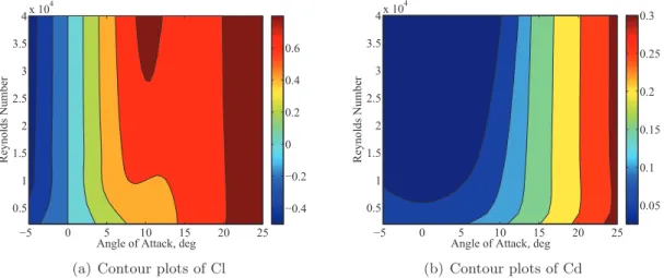
Angle of Attack, deg
Reynolds Number −5 0 5 10 15 20 25 0.5 1 1.5 2 2.5 3 3.5 4x 10 4 0.05 0.1 0.15 0.2 0.25 0.3 (b) Contour plots of Cd
Figure 1: Airfoil characteristics of NACA0012
Angle of Attack, deg
Reynolds Number −5 0 5 10 15 20 25 1 1.5 2 2.5 3 3.5 x 10⁴ −0.4 −0.2 0 0.2 0.4 0.6 0.8 1 1.2
(a) Contour plots of Cl
Angle of Attack, deg
Reynolds Number −5 0 5 10 15 20 25 1 1.5 2 2.5 3 3.5 x 10⁴ 0.05 0.1 0.15 0.2 0.25 0.3 0.35 (b) Contour plots Cd
Figure 2: Airfoil characteristics of modified MA409
4F λ2
rdr= 1 2σClr
2
dr. (2)
Eq. 2 allows for the solution of induced flow ratio along the blade radius for a given rotor with certain chord distribution, collective pitch, twist distribution and airfoil
section. The result will be converged through a few iterations. In propeller analy-sis, the form of BEMT developed by Adkins was employed [9]. In this model, the inflow ratio or inflow angle is iteratively computed until the convergence criteria are reached. The database of airfoil characteristics are obtained from Xfoil, which is an airfoil design and analysis code developed by Drela [10]. BEMT model was validated using existing performance data of rotor and propeller. The detailed geometries of them are described in [11] and [12]. The airfoil of rotor defined by NACA0012 while the propeller airfoil is based on a modified MA409. Xfoil can not always give a con-verged solution of airfoil performance for given airfoils. Hence, in order to obtain a smooth database for BEMT convergence, it is necessary to conduct interpolation for lift coefficient Cl, drag coefficient and Cdand moment coefficient Cm with variation
to angle of attack and Reynolds numbers. The Ncrit to predict the flow transition is 0.1 for rotor and 7.0 for propeller corresponding to different turbulence intensities [12, 13]. Fig. 1 and Fig. 2 show the interpolated results on Cl and Cd. Fig. 3 and
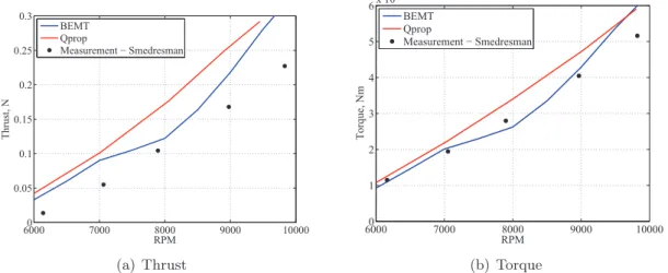
Fig. 4 exhibit the validation of performance predictions of the rotor and propeller. The BEMT model over predicts the thrust of rotor slightly while the torque matches well with experiment data. This is probably from that, as the wake becomes tur-bulent for heavy loading, air with momentum is transported from the outer flow region into the wake. The accuracy of BEMT model is decreased by the strong self-induction wake. Also, under heavy disk loading, the assumption of rigid wake sheet for Prandtl tip-loss function becomes not accurate enough. With respect to propeller, it is found that the developed BEMT method incorporated with database agrees better with the experimental data compared to the linear model Qprop [14]. However, for high disk loadings, the results predicted by Qprop which is capable of considering self-induction wake, show potentially better trends.
20000 2500 3000 3500 4000 4500 5000 5500 0.1 0.2 0.3 0.4 0.5 0.6 0.7 0.8 RPM Thrust, N BEMT Measurement − Bohorquez (a) Thrust 20000 2500 3000 3500 4000 4500 5000 5500 1 2 3 4 5 6 7 8x 10 −3 RPM Torque, Nm BEMT Measurement − Bohorquez (b) Torque
Figure 3: BEMT validation for rotor
Overall, the BEMT is an efficient tool for at least preliminary analysis of the span-wise distribution of airloads, especially due to the negligible computational cost of this method.
60000 7000 8000 9000 10000 0.05 0.1 0.15 0.2 0.25 0.3 RPM Thrust, N BEMT Qprop Measurement − Smedresman (a) Thrust 60000 7000 8000 9000 10000 1 2 3 4 5 6x 10 −3 RPM Torque, Nm BEMT Qprop Measurement − Smedresman (b) Torque
Figure 4: BEMT validation for propeller
Number of blades Radius (m) Hub radius (m) Chord (m) Built-in twist (deg) 2 0.2 0.03 0.03 -10/-15/-20/-25/-30
Table 1: The blades with varied built-in twist
Hover Forward flight RPM 1500 1200 Velocity (m/s) 0 10 Advance ratio, J / 1.25
Thrust (N) 2 0.3 Thrust coefficient 0.01 0.003
Table 2: Operation conditions of MAVion
3
Twist effect on the efficiency of small proprotor
In order to study the twist effect on the efficiency of small proprotor, five blades with varied built-in twist are defined first, as shown in Tab. 1. For example, twist -10 represents that twist of blade tip is lower than the counterpart of blade root by 10◦ with linear distribution. The airfoil of the blade is flat plate with a thickness of
2.5%. Tab. 2 exhibits the operation conditions for both hover and forward flight. Fig. 5(a) shows the twist effect on hovering efficiency - Figure of Merit (FM) with the variation to thrust coefficient. Thrust coefficient is adjusted by collective pitch for the five blades. The blade with built-in twist 10◦ has the maximum efficiency at
CT=0.01. In Fig. 5(b), the propulsive efficiencies of the five blades are all analyzed
under CT=0.003. They vary with the advance ratios in forward flight. The blade
with twist 30◦ exhibits highest efficiency of all at advance ratio J=1.25. Overall,
as we can see from Fig. 5, high twist of blade is beneficial for forward flight while low twist can improve hovering efficiency. According to the mission requirement of MAVion, the solution of proprotor for MAVion is given in Tab. 3.
0 0.005 0.01 0.015 0.02 0 0.1 0.2 0.3 0.4 0.5 0.6 Thrust coefficient, C T FM Twist 10 Twist 15 Twist 20 Twist 25 Twist 30
(a) Twist effect on rotor efficiency
0.8 0.9 1 1.1 1.2 1.3 0 0.1 0.2 0.3 0.4 0.5 0.6 0.7 0.8 Advance ratio
Propulsive efficiency Twist 10
Twist 15 Twist 20 Twist 25 Twist 30
(b) Twist effect on propeller efficiency
Figure 5: Twist effect to small proprotor Hover Forward flight Built-in twist (degree) 10 30 Collective pitch (degree) 31 54
Table 3: Optimized proprotor of MAVion
4
FSI Model
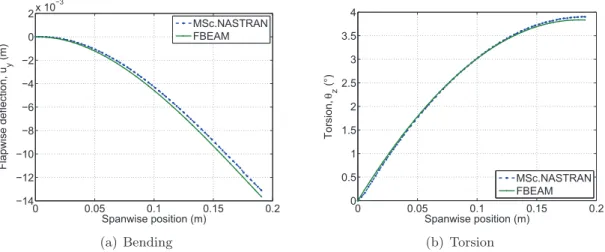
In order to compute the blade deformation under airloads and centrifugal loads, the coupled FSI model of the proprotor combines the aerodynamic model - BEMT and structural analysis model model - FBEAM, which was developed by Mohd-Zawawi [15]. To begin with, the basic geometry (zero deflections) is assumed. Then the structural model calculates the blade deformations under airloads and centrifugal loads. The deformed blade shape is used to update the aerodynamic model. The quasi-steady aerodynamic loads are computed for the update geometry, using the 2D aerodynamic theory based on BEMT. The aerodynamic loads are transferred to the beam nodes as concentrated forces. A new structural analysis is performed to calculate the deformed shape of the blade under the influence of aerodynamic and centrifugal loads. The variation of the blade twist angle along the blade is monitored for convergence. The interaction is repeated until equilibrium between deformation and loadings is achieved. After convergence the proprotor performance character-istics are computed. The approach described above was applied to the constant chord untwisted 2-bladed system for small proprotor made of laminate composite. The deflection results in two basic modes of deformation; spanwise bending and torsion. The effects of camber changes are not included in this study due to lim-itation in the modeling. Firstly, a static analysis on a rectangular planform with dimension (length 190.5mm, width 12.7mm, thickness 3.175mm) was performed. Carbon/Epoxy with material properties E11=129GPa, E22=9.4GPa, E33=9.4GPa, G12=5.16GPa, G13=4.3GPa, G23=2.54GPa, µ=0.3 and ρ=1550kg/m3
was used. The ply angle with respect to pitch axis was 30◦. The result obtained in FBEAM
was validated by commercial structural analysis program namely MSc. Nastran and the validation result is illustrated in Fig. 6.
0 0.05 0.1 0.15 0.2 −14 −12 −10 −8 −6 −4 −2 0 2x 10 −3 Spanwise position (m) Flapwise deflection, u y (m) MSc.NASTRAN FBEAM (a) Bending 0 0.05 0.1 0.15 0.2 0 0.5 1 1.5 2 2.5 3 3.5 4 Spanwise position (m) Torsion, θz (°) MSc.NASTRAN FBEAM (b) Torsion
Figure 6: Static validation of FBEAM
5
Experimental setup
(a) Thrust and torque tests (b) LDS measurement
Figure 7: Experimental rigs
The blade was fabricated using Carbon/Epoxy with a stacking sequence [45]5, and
clamped with a collective pitch 15◦. The geometry properties are the same with
counterparts in Tab. 1 but without built-in twist. The two blades were driven by a high torque brushless motor - ATI 2208/24. To evaluate the flexible blade performance, the thrust and torque were measured using two transducers. The close-up view of the sensors and mounted blade can be seen in Fig. 7(a). In order to reconstruct the rotating blade, two LDSs are driven by track systems to scan the blade from blade root to tip with an incremental distance 2mm (Fig. 7(b)). The LDS used in experiment is KEYENCE LK-G502. The distance of reference is 500mm, and the range of measuring can be between -250mm to 500mm. The sampling frequency of this laser was selected as 10,000Hz. LDS records the Z coordinates (along the direction of height) which is the distance from the position detected on blade surface
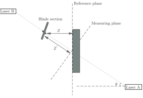
Laser A Laser B Blade section Reference plane Measuring plane Z Z′ θ
Figure 8: Measuring principle
to reference plane. Meanwhile, square wave in time domain is measured by optical RPM sensor. Then, average RPM and angular speed at each blade section can be extracted from the square wave. Furthermore, with the azimuth of feathering, polar coordinates is possible to be transferred to Cartesian coordinates X (along spanwise of blade) and Y (along chordwise of blade). Combining coordinates X, Y and Z, a polynomial surface fitting is performed to obtain the bending and torsion of rotating blade. As we can see, coordinates Z can be measured in a direct way by laser. However, coordinates X and Y are instead calculated by local radius of each scanning, angular speed of blade and sampling time,
X = rcos(wt) = rcos(RPM
60 2πt), (3)
Y = rsin(wt) = rsin(RPM
60 2πt), (4)
where r, w and t are local radius, angular speed and sampling time, respectively. The uncertainties UX and UY are defined by bias limits and precision limits using
the Root-Sum-Square (RSS) method [16], UX = (B 2 X + P 2 X) 1 2, (5) UY = (B 2 Y + P 2 Y) 1 2, (6)
where BX, PX, BY and PY are bias limits of X, precision limits of X, bias limits of
Y and precision limits of Y . The are defined by,
(BX X ) 2 = ( 1 X ∂X ∂r Br) 2 + ( 1 X ∂X ∂RPMBRPM) 2 + ( 1 X ∂X ∂t Bt) 2 , (7) (PX X ) 2 = ( 1 X ∂X ∂r Pr) 2 + ( 1 X ∂X ∂RPMPRPM) 2 + (1 Y ∂X ∂t Pt) 2 , (8)
(BY Y ) 2 = (1 Y ∂Y ∂rBr) 2 + (1 Y ∂Y ∂RPMBRPM) 2 + (1 Y ∂Y ∂tBt) 2 , (9) (PY Y ) 2 = (1 Y ∂Y ∂rPr) 2 + (1 Y ∂Y ∂RPMPRPM) 2 + (1 Y ∂Y ∂tPt) 2 , (10)
With respect to the real Z of blade to reference plane, as shown in Fig. 8, it is defined by,
Z = Z′cos(θ), (11)
where coordinates Z′
are the distance data to measuring plane obtained from LDS directly, θ is the measuring angle of lasers. This is to say, coordinates Z are needed to be transformed from measuring system to the reference system for the reconstruction of blade shape. UZ, it is defined by uncertainty of laser measurement directly,
UZ = (B 2 laser + P 2 laser) 1 2, (12)
where Blaser and Plaser are bias limits and precision limits of laser data. All of bias
limits are constants and they will not be affected by sampling. Local radius r is totally determined by track system while time t is from quartz crystal reference. Here, the precision limits of RPM are considered for uncertainties of coordinates X and Y . The precision limit of RPM is defined as,
PRPM=
1.96σRPM
√ NRPM
, (13)
where σRPMis the standard deviation of RPM and N is the RPM sampling number.
The distance to a reference was measured by laser sensor first to study precision limits of coordinates Z, the precision of displacement data is defined as,
Plaser =
1.96σlaser
√ Nlaser
, (14)
where σlaser is the standard deviation of measured distance by laser and N is the
laser sampling number.
6
Results
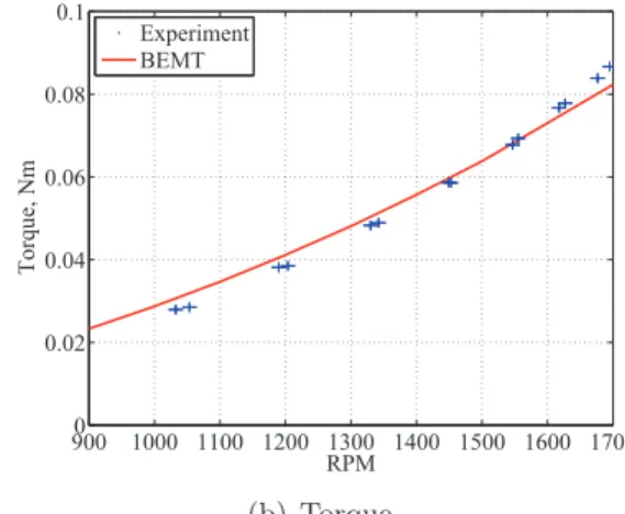
The laminate blade was tested at RPM 1,500 in hover mode. The comparison results between BEMT model and experimentsin performance are shown in Fig. 9. The errorbars represent the stand deviation of the mean of sampling data. In simulation, the input blade geometry for BEMT was assumed without deformation. As can be seen, the BEMT agrees well with experimental data of torque. However, it over-predicts the thrust. This is probably caused by the obvious bending deformation of rotating blade since it can generate the thrust vector in spanwise of blade. The precision limits of reference measurement was given by -35.8452±0.0008, as shown in Fig. 10(a). Besides, according to user’s manual of KEYENCE LK-G502, when the detection range is between -250mm and 500mm, the bias limits is given by ±0.1%. Based on Eq. 11, the uncertainty of coordinates Z is ±0.1%. This is to say, compared with bias limits, precision limits of laser can be negligible. The normal density of RPM samples from optic sensor are shown in Fig. 10(b). Finally, the uncertainty of RPM was given by 1,517.5±11.4. The uncertainty UX and UY were calculated using
9000 1000 1100 1200 1300 1400 1500 1600 1700 0.5 1 1.5 2 RPM Thrust, N Experiment BEMT (a) Thrust 9000 1000 1100 1200 1300 1400 1500 1600 1700 0.02 0.04 0.06 0.08 0.1 RPM Torque, Nm Experiment BEMT (b) Torque
Figure 9: Aerodynamic performance of laminate blade
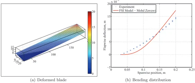
Eq. 5 and 6, as shown in Fig. 11 and 11. The blade was reconstructed through 3-D polynomial surface fitting of second order (Fig. 13(a)). Fig. 13(b) shows the bending distribution of rotating blade, and the errorbars are defined by the standard deviation of surface fittings along spanwise of blade. FSI simulation and experiment are capable of obtaining the bending distribution with approximately same order of magnitude. However, the curvatures of bending in FSI model and measurement are different especially around the blade root. The difference could be from composite properties in FSI model. Hence, it is necessary to measure the properties instead of using ideal characteristics. Also, initial scanning position of LDS may cause the curvature difference in bending.
−36.2 −36 −35.8 −35.6 −35.4 0 1000 2000 3000 4000 5000 Distance to reference Normal density
(a) Measured distance data
15000 1505 1510 1515 1520 1525 1530 1535 100 200 300 400 500 600 700 RPM Normal density (b) Measured RPM data
Figure 10: Normal density distribution
7
Conclusion
In conclusion, the evaluation of design techniques, both for the aerodynamic per-formance and for the structural behavior of a composite flexible proprotor has been presented in rotor mode. The numerical model BEMT has capability of prediction in proprotor aerodynamics. The results show high twist of blade is suitable for
X, mm Y, mm 50 100 150 200 −20 −10 0 0 0.05 0.1 (a) Uncertainties of X X, mm Y, mm 50 100 150 200 −20 −10 0 0 0.1 (b) Uncertainties of Y
Figure 11: Uncertainties on upper surface
X, mm Y, mm 50 100 150 200 −20 −10 0 0 0.05 0.1 (a) Uncertainties of X X, mm Y, mm 50 100 150 200 −20 −10 0 0 0.1 (b) Uncertainties of Y
Figure 12: Uncertainties on lower surface
50 100 150 200 −20 −100 0 5 10 15 0 5 10 15 20
(a) Deformed blade
0 0.05 0.1 0.15 0.2 0.25 −5 0 5 10 15 20x 10 −3 Spanwise position, m Flapwise deflection, m Experiment
FSI Model − Mohd Zawawi
(b) Bending distribution
Figure 13: LDS results
propulsive efficiency while low twist is beneficial for hovering efficiency. FSI model has also been validated by LDS technique. The difference of bending distribution is expected to be studied further in terms of materials properties and experiment procedure. It can be concluded that the developed numerical model is a reliable tool for designing and analyzing the proprotor made of composite material. Addition-ally, current laminate was not observed deforming in beneficial torsion. In future, in order to obtain obvious torsion, the study will focus on the configuration design of laminate blade. Likewise, the experiments will also be expanded to propeller mode.
Acknowledgements
The authors thank Rémy CHANTON, Patrick MOREL, Philippe BARRICAU, Serge GERARD, Patrick CAZENAVE, Philippe MOULIGNE and Xavier FOULQUIER for advice and assistance. The research is supported by China Scholarship Council (CSC) and Malaysian government.
References
[1] McVeigh M.A., Rosenstein H.J. 1983 Aerodynamic design of the XV-15 advanced composite tilt rotor blade 39th Annual Forum of the American Helicopter Society 72-80
[2] Nixon M.W. 1988 Improvements to tilt-rotor performance through passive balde twist control. NASA Technical Memorandum 100583 1-9
[3] Shkarayev S., Moschetta J.M., Bataille B. 2008 Aerodynamic design of micro air vehicles for vertical flight. Journal of Aircraft 45 1715-1724
[4] Williams D. C. 1993 Optical methods in engineering metrology. Chapman and
Hall
[5] Fleming G. A., Gorton S. 1998 Measurement of rotorcraft blade deformation us-ing projection moire interferometry. Proceedus-ings of the Third International
Con-ference on Vibration Measurements by Laser Techniques: Advances and Appli-cations, SPIE–the International Society for Optical Engineering, Ancona, Italy
514-527
[6] Schmidt T., Tyson J., Galanulis K. 2003 Full-field dynamic displacement and strain measurement using advanced 3D image correlation photogrammetry: Part 1. Experimental Techniques 27 47-50
[7] Lawson M.S., Sirohi J. 2011 Measurement of deformation of rotating blades using digital image correlation. 52nd AIAA/ASME/ASCE/AHS/ASC Structures,
Structural Dynamics and Materials Conference, Denver, Colorado AIAA
2011-1876 1-15
[8] Leishman, J.G. 2006 Principles of helicopter aerodynamics. Cambridge Aerospace
Series, 2nd edition
[9] Adkins C.N. 1990 Design of optimum propellers. Journal of Propulsion and
Power 10 676-682
[10] Drela M. 1989 An analysis and design system for low Reynolds number airfoil, low Reynolds number aerodynamic. Springer–Verlag, New York 1-12
[11] Bohorquez F. 2007 Rotor hover performance and system design of an efficient coaxial rotary wing micro air vehicle. Ph.D thesis, University of Maryland [12] Smedresman A., Yeo D., Shyy W. 2011 Design, fabrication, analysis, and testing
of a micro air vehicle propeller. 29th AIAA Applied Aerodynamics Conference,
Honolulu, Hawaii AIAA 2011-3817 1-16
[13] Schafroth D.M. 2010 Aerodynamics, modeling and control of an autonomous micro helicopter. Ph.D thesis, ETHZ
[14] Drela M. 2007 Qprop user guide. MIT
[15] Moha-Zawawi F., Prothin S., Lv P., Benard E., Moschetta J.M., Morlier J. 2013 Study of a flexible UAV proprotor 48th International Symposium of Applied
Aerodynamics Saint-Louis. FP30-2013 1-10
[16] Taylor J. R. 1996 An introduction to error analysis: the study of uncertainties in physical measurements. University Science Books, Sausalito, California