HAL Id: hal-02441900
https://hal-cea.archives-ouvertes.fr/hal-02441900
Submitted on 26 Feb 2020HAL is a multi-disciplinary open access
archive for the deposit and dissemination of sci-entific research documents, whether they are pub-lished or not. The documents may come from teaching and research institutions in France or abroad, or from public or private research centers.
L’archive ouverte pluridisciplinaire HAL, est destinée au dépôt et à la diffusion de documents scientifiques de niveau recherche, publiés ou non, émanant des établissements d’enseignement et de recherche français ou étrangers, des laboratoires publics ou privés.
SEM analyzes of powdered actinide compounds :
Implementation in a hot laboratory
G. Jouan, J.R. Sevilla, M. Virot, E. Buravand, C. Valot
To cite this version:
G. Jouan, J.R. Sevilla, M. Virot, E. Buravand, C. Valot. SEM analyzes of powdered actinide com-pounds : Implementation in a hot laboratory. HOTLAB 2016 - the 53rd Annual meeting on ’hot’ laboratories and remote handling in cooperation with the International Atomic Energy Agency, Oct 2016, Karlsruhe, Germany. �hal-02441900�
HOTLAB2016
SEM analyzes of powdered actinide compounds:
Implementation in a hot laboratory
G. JOUAN1, J.R. SEVILLA1, M. VIROT2, E. BURAVAND3, C. VALOT1
1 - CEA, DEN, DTEC/SECA/LCC, F-30207 Bagnols-sur-Cèze Cedex, France 2- CEA, DEN/MAR/ICSM/DIR/LSFC, F-30207 Bagnols-sur-Cèze Cedex, France
3- CEA, DEN, DRCP/SERA/LED, F-30207 Bagnols-sur-Cèze Cedex, France Abstract
The fuel characterization laboratory in CEA Marcoule (LCC : “Laboratoire de Caractérisations des Combustibles”) works on radioactive solid characterization and especially on minor actinide powders (U, Pu, Am, Cm, ...). The powder disadvantage is to generate an important contamination inside the glove boxes and the equipment used for their characterization. The present communication is dedicated to a nuclearized FEG-SEM Zeiss Supra 55. This device is equipped with EDS and WDS combined detectors. The SEM is connected to a glove box on its sample introduction chamber with a flexible bellow in order to minimize ventilation vibrations. This type of nuclearization allows the SEM to be uncoupled from its glove box and highly simplifies its maintenance by avoiding contamination.
In a first part, we will present the SEM nuclearization with curative maintenance examples (detector replacement and modifications). We will also discuss the feedback on EDS detector changes done in order to limit radiation impact. Induced effects by these changes will be discussed.
In the second part, we will detail some results obtained with different detectors (SE2, BSE, InLens, EDS and WDS), and focus on analyzes performed in support of irradiated fuel reprocessing studies just after their dissolution. Zirconium molybdate precipitates are formed during the dissolution process causing significant fouling on the reprocessing process walls. The goal of this study realized in the high activity Laboratory Atalante is to control the precipitate growth in order to minimize their impact on the process. We will present some images and elemental analyzes performed on these samples, and what the nuclearized SEM enabled to highlight.
A final section will demonstrate the interest of using a WDX detector in the case of radioactive samples, especially in the case of fission product separation (platinum group elements) or characteristic X-ray lines of actinides (Pu and Am for example).
1. Introduction
In June 2010 a nuclearized scanning electron microscope (SEM) was implemented in the Atalante facility in LEGS building (laboratory equipped with process in safe geometry) at the -1st level. This instrument is actively involved in many R&D programs (nuclear waste, actinides powders or pellet, fuel, dissolution residues …) in term of microstructural or elemental analysis. Since 2015 this equipment has been attached to the LCC : “Laboratoire de Caractérisations des Combustibles” (fuel characterizations laboratory) which focuses on several solid characterizations (SEM, XRD, XRD in temperature, EPMA, BET, TGA …) and especially on minor actinide powders (U, Pu, Am, Cm, ...). This equipment can perform characterizations on radioactive samples with the particularity to accept powders in its chamber. The powder disadvantage is to generate an important contamination inside the glove boxe and the equipment. That is why its nuclearization configuration has been optimized to avoid
contamination except in its chamber1. Since 2010, this apparatus has shown an excellent
versatility on really different samples in term of imaging and elemental separations.
2. Equipment description
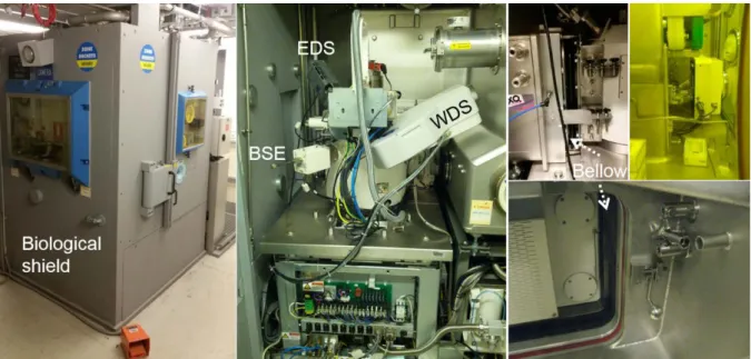
The SEM implemented in the LES216 laboratory is a FEG Zeiss SUPRA 55 equipped with EDS and WDS combined detectors (Oxford Instruments) shown in Figure 1. The SEM and its glove box had to be in a biological shield already present in the LES216. In order to avoid external contamination, the SEM is connected to a specially designed glove box on its sample introduction chamber with a flexible bellow to minimize ventilation’s vibrations.
Figure 1: Pictures of the biologic shield and the SEM connected to its glove box
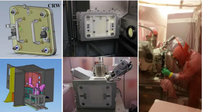
This type of nuclearization allows the SEM to be uncoupled from its glove box using a LaCalhène system (CRW) and highly simplifies its maintenance by avoiding external contamination. After being uncoupled, the SEM can be translated on two rails to maintain the different parts (Figure 2). In 6 years, numerous maintenances have been performed successfully such as EDS detector modification, diaphragm replacement, magnetic brake setting, BSD replacement...
Figure 2: pictures of the CRW-door, the disconnected SEM / glove box and of a maintenance in the chamber
The SEM is equipped with different imaging detectors: - Everhart-Thornlay for secondary electrons detection
- InLens situated in the column to detect secondary electrons (type 1 only) with higher resolution reachable (4 nm)
- BSD retractable for back scattered electrons giving a topographic or chemical contrast And elemental analysis detectors:
- EDS (energy dispersive spectroscopy) Oxford Instruments Xact model (modified). - WDS (wavelength dispersive spectroscopy) Oxford Instruments Rowland’s circle
configuration.
To limit radiation’s impact on EDS detector, Oxford Instruments company has changed with CEA its regular configuration by adding a beryllium window of 12 µm (thickness of 25 µm at the beginning) and a smaller collimator with a diameter of 0.1 mm (versus 0.5 mm in standard). This particular configuration involved to make EDS measurements with the largest diaphragm which has a diameter of 240 µm and to count at least 60 seconds per spectra. The beryllium window absorbing the characteristics X-ray at low energy, this detector is able to detect elements heavier than sodium.
In order to detect light elements and to separate some compounds a WDS has been installed. It is used especially in the case of fission products separation (platinum group elements) or characteristic X-ray lines of minor actinides (Pu and Am M rays for example).
EDS and WDS spectrometers are yearly standardized using a MAC 55 standards grid. Actinides standards are “homemade” without certification.
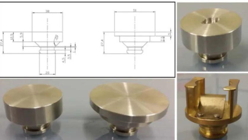
NOTE: to minimize the contamination in the chamber and to adapt each sample preparation the sample holders are disposable with the possibility to design them as shown in Figure 3.
Figure 3: example of sample holder designed and realized in Atalante for the SUPRA 55 SEM.
3. Results and examples
3.1. Reductive dissolution of PuO
2assisted by ultrasound in the presence of Ti
particles
Once discharged, the spent fuel can be retreated through several dissolution and separation steps (PUREX) in order to recycle uranium, plutonium and to condition non-recoverable fissions products2-5. This process offers an almost complete dissolution in nitric acid media with
a very low quantity of remaining solid granulates (0.1%). These residues, potentially composed of plutonium, can be more important in the case of MOX fuel depending on its preparation and initial Pu content6-8. Moreover, the plutonium dioxide is a very refractory compound towards
dissolution in nitric acid (hard and dense)4,6. However PuO
2 is considered as an important
compound for the current and future nuclear fuel. To optimize PuO2 dissolution, innovative
approaches are studied as ultrasound assisted route for example.
Dissolution studies were performed in CEA Marcoule 9 using ultrasound assisted reductive
dissolution of PuO2 in the presence of Ti particules. The aim of the SEM study was to observe
the oxide morphology evolution as a function of the dissolution progress to understand the influence of various parameters such as the composition of the solution, the presence of ultrasound and the nature of the bubbling gas. In all cases, the dissolutions are performed in the presence of titanium particles of about 45 microns in diameter. The different concentrations were monitored by ICP-OES measurements and UV-Vis spectrometry but won’t be discuss in this paper. Powders microstructures were observed by SEM.
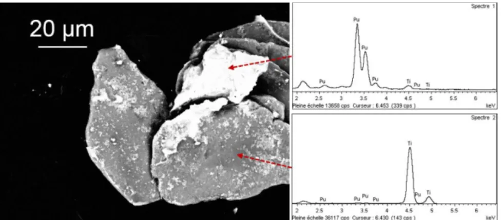
SEM pictures and EDS analysis confirmed the presence of Ti particles with smaller plutonium particles stuck on. The micrographs have mostly been performed using a backscattered electron detector in composition mode to bring out the plutonium in light and titanium in dark.
Figure 4: SEM (ETD and BSED) pictures of (a) the initial PuO2 sample ; (b) sonochemical dissolution residues (20 kHz, 0.45 W mL−1,
Ar, 7 h, 140 mg of Ti 325 mesh, 35 °C) observed for PuO2 (SBET = 5 m2 g−1) in 1 M HNO3/2 M HCOOH/0.1 M HN (V = 50 mL) with the
injection of NH4F (10 mM) after 180 min of sonication and (c-d) in same conditions except HCOOH is replaced by NHA at 2M. Pu
appears in bright colors and Ti in dark.
Figure 5: SEM BSD picture of the residues described in the previous figure and EDS spectrum associated
The application of ultrasound seems essential to break the PuO2agglomerates initially present
and facilitate their dissolution. In all cases the observed dissolution fines have a spherical microstructures with a diameter of one hundred nanometer. The majority is adsorbed on the titanium particles. However, it is unclear whether the PuO2 agglomerates on titanium particles
during the process of dissolution or during the centrifugation step.
The previously discussed dissolution fines are also composed of several fission products such as platinum group elements. SEM characterization have been done on residues isolated by filtration of a spent fuel dissolution solution in the C11/C12 shielded lines of the Atalante facility. It is almost impossible to determine with precision their composition with an EDS detector because most of their characteristic X-rays appear at the same energy range (Ru, Rh et Pd Lα1 rays are respectively at 2.342, 2.558 and 2.838 keV) as shown on the EDS spectra on
Figure 6. The use of a WDS detector is essential to separate the contribution of each Lα1
rays and to determine the composition of the residual particles.
Figure 6: EDS and WDS spectrum done on dissolution fines shown on the SEM picture
3.3. Attempt to control the nucleation and crystal growth of zirconium
molybdate hydrate in nitric acid
The first stage of the spent fuel reprocessing performed Areva at “La Hague” plant is to dissolve the spent fuel in nitric acid at high-temperature. Molybdenum and zirconium, two fission products, generate precipitates in the form of zirconium molybdate ZrMo2O7(OH)2, 2H2O10. These precipitates can be deposited on the surface of the equipment and especially in tank bottom (heating zone).
To avoid this fouling phenomena, R&D programs are focused on the comprehension of the thermodynamics and kinetics parameters which drive the nucleation and crystal growth of zirconium molybdate hydrate in nitric acid11. A way of prevention explored in Atalante CEA is to limit the growth by changing the solution dissolution composition. To illustrate these studies stainless steel plates have been submerged in a dissolution solution charged with dissolved spent fuel and additives in C11/C12 shielded lines. The precipitates formed during different times and conditions were dried and characterized by SEM.
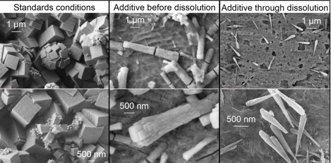
Figure 7 : SEM (ETD) pictures of Mo / Zr precipitates formed after 22 hours in standards conditions, with an additive before the introduction of the spent fuel and through the dissolution process in the same amount.
The micrographs in Figure 7 demonstrate an important diminution of the precipitates size and an evolution of their microstructure from parallelepipeds with a square base to conical needles. Furthermore, without additives, the stainless steel plates are entirely covered with Mo / Zr precipitates after 22 hours. On the contrary, with additives, and particularly when it is added through the dissolution process, the plates are only partially covered with isolated conical needles.
Elemental analysis performed by EDS revealed an evolution of the ratio Mo / (Mo + Zr) described in the graph (Figure 8). The EDS measurements are done on non-plane samples. To reduce the measurement errors, the values given in the Figure 8 are average values obtained done on at least 30 spectra (SD < 2%at). These values do not take into account the measurement uncertainty related to the sampling and the equipment (estimated at 2%).
Figure 8 : Mo and Zr ratio in the precipitates determined by EDS with 1 for the additive added through the spent fuel dissolution, 2 added before the dissolution and 3 without additive.
These results suggest an important role of the additive in the evolution of the composition of the Mo / Zr precipitates and their associated microstructure. The crystal growth mechanism seems partially changed by the presence of this additive by guiding the Mo and Zr ions not on
the lengths of the rectangular faces, reducing their widths. That's why without the additive, precipitates are parallelepipeds square base rectangles. Then, with a partial inhibition (additive before dissolution), the precipitates are flared sticks with a rounding edges while maintaining a well-defined squared basis. Growth steps are rectangular with smaller widths than the precipitate. At the extreme (additive through dissolution), the precipitates are cones with growth steps having very small widths (rectangles have become wires).
1 - C. Léorier, S. Caron, D. Courroye, C. Brenneis, M. Widehem, R. Platon, J.-P. RigotardBarbadoro, F. Dubuc, S. Chalal, patent WO2013/068321 A1, 2013. 2 - C. Poinssot and B. Boullis, Nucl. Eng. Int., 2012, 57, 17–21.
3 - C. Poinssot, C. Rostaing, S. Grandjean and B. Boullis, Proc. Chem., 2012, 7, 349–357. 4 - D. Clark, S. Hecker, G. Jarvinen and M. Neu, in The Chemistry of the Actinide and Transactinide Elements, ed. L. Morss, N. Edelstein and J. Fuger, Springer, Netherlands, 2011, chapter 7, 813–1264.
5 - A. P. Paiva and P. Malik, J. Radioanal. Nucl. Chem., 2004, 261, 485–496.
6 - Treatment and Recycling of Spent Nuclear Fuel – Actinide Partitioning – Application to Waste Management, Monographie DEN, Editions Le Moniteur, France, 2008.
7 - H. Ikeuchi, A. Shibata, Y. Sano and T. Koizumi, Proc. Chem., 2012, 7, 77–83.
8 - M. J. Carrott, P. M. A. Cook, O. D. Fox, C. J. Maher and S. L. M. Schroeder, Proc. Chem., 2012, 7, 92–97.
9 - X. Beaudoux, M. Virot, T. Chave, G. Leturcq, G. Jouan, L. Venault, P. Moisy and S. I. Nikitenko, Dalton Trans., 2016, 45, 8802.
10 - Y. Kondo, M. Kubota, Journal of Radioanalytical and Nuclear Chemistry, 1997, 221, 45. 11 - A Magnaldo, M Masson, R Champion, Chemical engineering science, 2007. 62, 766-774.