HAL Id: hal-00510258
https://hal-mines-paristech.archives-ouvertes.fr/hal-00510258
Submitted on 18 Aug 2010HAL is a multi-disciplinary open access archive for the deposit and dissemination of sci-entific research documents, whether they are pub-lished or not. The documents may come from teaching and research institutions in France or abroad, or from public or private research centers.
L’archive ouverte pluridisciplinaire HAL, est destinée au dépôt et à la diffusion de documents scientifiques de niveau recherche, publiés ou non, émanant des établissements d’enseignement et de recherche français ou étrangers, des laboratoires publics ou privés.
Injection of thermoset foam: comparison between
simulation and experiment
Rabea Bouayad, Jérôme Bikard, Jean-François Agassant
To cite this version:
Rabea Bouayad, Jérôme Bikard, Jean-François Agassant. Injection of thermoset foam: comparison between simulation and experiment. 11th ESAFORM Conference on Material Forming, Apr 2008, Lyon, France. pp.683-686, �10.1007/s12289-008-0307-6�. �hal-00510258�
1 INTRODUCTION
Flexible polyurethane foams are usually applied in car seat parts. Optimisation of the manufacturing process, as well as part quality may be improved through numerical modelling. Flexible PU foams are produced in a one shot process in which (poly)isocyanate, polyols and water are mixed simultaneously with suitable stabilisers, catalysts and cell(size control agents. The chemical reactions begin immediately, with foam rise starting a few seconds after mixing and being completed in a matter of minutes. Curing continues for several hours, eventually leading to a solid cellular material [1,2].
The two primary reactions are the curing reaction, which leads to formation of polyurethane, and the expansion reaction, producing polyurea and carbon dioxide, with simultaneous expansion of CO2
bubbles (foaming) and polymerization of the mixture. The first step of the expansion is bubble nucleation, where CO2 molecules dissolved in the
mixture initiate micro(bubbles, under the effect of pressure decrease at the exit of the injection syringe into the mould. At a macroscopic scale, the nuclei can be modelled by an initial porosity of the gas/polymer mixture. Two mechanisms have to be distinguished at this scale: the expansion by difference of pressure and by gas creation. During
fabrication of this foam, the rheological properties of its skeleton evolve from a viscous liquid to a viscoelastic (or elastic) solid.
The objective of the present work is the identification of several parameters of a numerical model of foam expansion developed at CEMEF [3] by comparison between experiments in a cylindrical mould and numerical computations.
Section 2 presents the physical assumptions and the equations of the model. The first part of section 3 is devoted to the presentation of the experiment used to identify some parameters of the model. The last part of section 3 shows a comparison between these experiments and numerical simulations.
2 MODELLING
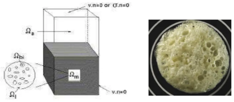
The objective of the model is to predict at a macroscopic level the expansion of the foam (corresponding to domain 8m characteristic of the
foam sample shown on Fig. 1.) into a mould (domain 8). It is based on the conservation equations (mass and stress balance), which are written by considering that 8m is a homogenized
medium (polymer 8l + gas bubbles 8bi,
i=1,2,…,Nbubbles). The interactions between polymer
and gas bubbles are described by the evolution of the porosity
φ
[1,4]. The free surface between 8mandair 8a(see Fig. 1.) is a result of the numerical model
ABSTRACT: The quality (cellular homogeneity, mechanical properties) of polyurethane foam's structures mainly depends on the manufacturing process, during which two concomitant (principal) exothermic chemical reactions take place: the first one creates CO2 into the fluid matrix (germination of bubbles,
expansion and coarsening of the foam) and the second one leads to the polymerization. In order to validate a model developed at CEMEF, an original experiment (RheoFoam System) has been created. It consists in an instrumented injection mould (closed or opened cylindrical cavity) in which the viscoelastic foam inflates. It allows measuring simultaneously the evolution of some technological parameters (the rise of the foam, the pressure distribution on the bottom of the mould and the temperature evolution inside the foam) which are a macroscopic signature of the evolution of the cellular microstructure. These temperature and pressure fields are then compared to those obtained using the numerical simulation. The results are discussed.
Key words: foam expansion, chemical reactions, diphasic medium, finite element modeling, experiments
Injection of thermoset foam: comparison between simulation and
experiment
R. Bouayad
1,2, J. Bikard
2, J.F. Agassant
21
FAURECIA AUTOMOTIVE SEATING S.A. ZI Brières les Scellés 91152 Etampes Cedex
2
Ecole des Mines de Paris, Centre de Mise en Forme des Matériaux, UMR CNRS 7635 – 06904 Sophia Antipolis, France
URL: www.cemef.cma.fr e5mail:[email protected] [email protected]
(section 3.2).
Fig. 1. left: Scheme of the mould containing PU mixture (gas+polymer, 8m) and the air (8a). The contact with the mould
is assumed perfectly sticking (v.n=0) ; right: a sample of PU foam (average radius 2cm).
Due to the fact the chemical reactions are strongly exothermal, the model takes into account the thermo(mechanical couplings.
2.1 Global mass conservation
The global mass conservation leads to the following local equation in 8m: dt d v
φ
φ
− = ⋅ ∇ 1 1 (1)where v is the expansion velocity of the foam. 2.2 Kinetics evolution laws
Gas creation and curing reactions are governed by chemical kinetics, whose conversion rates are supposed to follow evolutions law [1,2]. Concerning gas creation, the following Kamal law is assumed [5] in 8m: ) ) ( ( ) 1 ( ) ( α α α λ α α µ ν ∇ ⋅ ∇ + − = ∇ ⋅ + ∂ ∂ T D T v t g g g g (2)
where α is the characteristic rate of gas creation,
1
−
g
λ
its characteristic time (depending on the temperature) and Eg and υg the exponents of thisreaction. Dg represents the diffusion coefficient of
gas into the polymer. Assuming a perfect gas law in the bubbles, the porosity development can be macroscopically written [3] in 8mby:
+ − − = dt dT T dt dp p dt d dt d 1 1 1 ) 1 ( α α φ φ φ (3)
where p is the hydrostatic pressure in the foam. The polymerization reaction leads to the viscosity increase of the matrix as a function of the
temperature up to a gel point. The curing rate is supposed to follow also a Kamal law [5] in 8m:
p p p T v t υ µ β β λ β β ) 1 ( ) ( − = ∇ ⋅ + ∂ ∂ (4)
β
is the characteristic rate of the cure,λ
p−1 its characteristic time and ?p and υp two exponents ofthe reaction.
2.3 Quasi5static balance equations
Experimentally, the global expansion of PU foams is slow (the strain rate is about 10(2 s(1). Assuming a quasi(static evolution, the balance equations reduced to [3]: Ω Ω = Ω − = = Ω Ι − ∇ − ∇ = = Ω = m a a a a m Sym Sym l n I p p v I v β η div on 0 . in in : 3 1 ). , , ( 2 in 0 σ σ σ φ γ σ σ σ (5) where
σ
is the Cauchy stress tensor, ε(v) the strain rate tensor,γ = 2ε(v):ε(v) the second invariant of the strain rate tensor, η the viscosity of the mixture, pa the pressure in the air. The interface conditionsassume the continuity of the normal velocity and the normal stress (the interfacial tension is neglected, this is a strong hypothesis).
2.3 Energy balance
From thermodynamical considerations, the heat equation can be written by:
(6) where
δ
Hα,β are the enthalpies of both reactions,C
ρ
is the heat capacity and λT the thermal conductivity.2.4 Rheological coupling
The matrix is considered as a shear(thinning fluid, whose behaviour is expressed by a Carreau law: ) ( ) ( ) ( 1 ) ( ) , , ( 2 1 2 2 0 γ φ β η β φ γ η T a T f g m ref − • • + = (7)
where η0 is the Newtonian plateau viscosity,
v p v T T dt d H dt d H T dt dT C dev S T ⋅ ∇ − ∇ ∂ ∂ + + + + ∇ ⋅ ∇ = • ) ( : ) ) ( ( ) ( 2 σ γ η β δ α δ α λ α ρ α β
following a classical Arrhénius law, a is a characteristic time and m the power(law exponent. Expansion and curing reactions will modify the viscosity of the fluid through two functions f and g, which follow the model developed by Castro and Macosko [6]:
and (8)
where βgel is the gel point and f
0, f1, f2 and ng are
positive constants.
3 ESTIMATION OF SOME RHEOLOGICAL PARAMETERS
The characteristic value of several parameters can be found in literature (see Table 1). Some of them can be identified using dynamic rheology experiments [7].
Table. 1. Values of parameters used in the model.
Resolution of the model in an axisymmetric configuration and comparison with well instrumented experiments allow to identify more precisely these parameters.
3.1 Experiment
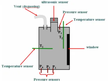
Fig. 2 shows the experimental cylindrical mould: the cylinder is closed after the components of PU have been mixed and put at the bottom of the mould. Pressure and temperature are recorded. Gas outlet during the expansion (gas initially present in the mould + degassed CO2) is also measured and
correlated to the expansion velocity of the foam.
Fig. 2. Photograph and Scheme of the experimental mould. After opening of the mould, one recovers a typical foam cylinder as shown on Fig. 3.
Fig. 3. Photograph of a typical foam cylinder manufactured using the RheoFoam.
3.2 Numerical resolution and comparisons
Equations (1(8) are highly coupled and non( linear. The numerical method is based on a splitting technique (used by [8] in the case of the microscopic simulation of PU expansion): at one time step, knowing T,
φ
and β, velocity and pressure fields are first determined through a mixed finite element method, verifying stability conditions [9]. The velocity is then used to compute temperature T, gas production α and solidification rate β. Finally, the moving interface between the gas(liquid mixture and air is computed, introducing a characteristic function of the mixture as additional unknown in each time interval [10] and solved by a volume of fluid method (V.O.F.) associated with a Space(Time Discontinuous Galerkin technique. The model has been implemented in the Rem3D® software [3]. Using characteristic values of parameters (see table 1), a numerical simulation is performed under the same conditions than the experiment described above, and then optimized in order to obtain a computed foam size equivalent to the experimentalλg(1 Eg λp(1 Ep νp η0 f0 1(2 min 0(2 1(10 min 0(2 0(2 102(103 mPa.s 1 F1 F2 βgel ng a M 1(10 0(1 0,9(1 1(5 0(10 s 0(1 ( ) g n gel gel g − − = β β β β 2 2 1 0 ) (φ f fφ fφ f = − +
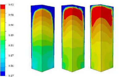
one. At that time the optimization loop The expansion results are shown on fig. 4: the gas rate is plotted on a cross section of the numerical cylinder respectively for 80, 100 and 150 s. (see also Figure 5). Due to the fact no nucleation mechanism has been taken into account, the gas rate can be directly correlated to the characteristic length of the foam cells. One observes that the larger ones are located close to the top of the foam.
Fig 4. Results of numerical simulation with Rem3D: expansion of the PU in the closed mould after 80, 100 and 120s.
Fig. 5 shows the good agreement between the experimental and numerical velocity fields up to about 100s (after optimization of parameters of table 1).
Fig. 5. Evolution of numerical and experimental height of the foam during expansion.
After 100s, agreement is less good, due to a bad description of the gas outlet during the expansion: this specific mechanism requires to improve the numerical description of the free surface of the foam, and to apply on it a more physical permeability condition. The viscoelasticity and the surface tension have also to be accounted for. Other experiments are then needed for a better estimation of the parameters.
4 CONCLUSIONS
In this paper, a simple experiment of expansion has been performed in order to identify the rheological parameters of the foam expansion model. The results show the good agreement between simulation and experiment up to the polymerization step, but the restrictive assumptions (no viscoelasticity, no permeability of the free surface) lead to discrepancies close to the gel point. We work now to overcome these limitations.
ACKNOWLEDGEMENTS
The authors are grateful to Mr. P. Motte and Mr. S. Vézine from FAURECIA S.A. for their technical assistance.
REFERENCES
1. L. Lefebvre, R. Keunings Mathematical Modelling and Computer Simulation of the Flow of Chemically5Reacting Polymeric Foams. In: Mathematical Modelling for Materials Processing, Cross M., Pittman J.F.T., Wood R.D. (eds). Clarendon Press: Oxford, 399(417 (1993) 2. S.L. Everitt, O.G. Harlen, H.J. Wilson, D.J. Read, Bubble
dynamics in viscoelastic fluids with application to reacting and non(reacting polymer foams, J. Non Newt. Fluid Mech., 114 83 (2003)
3. J. Bikard, J. Bruchon, L. Silva, T. Coupez : Numerical simulation of a 3D Polyurehtane expansion during manufacturing process, Colloids & Surfaces, A, Physicochemical and Engineering aspects. Volume 309, Issues 1(3, 49(63 (2007)
4. M. Amon, D. C. Denson, A study of the dynamics of foam growth: analysis of the growth of closely spaced spherical bubbles, Polym. Eng. Sci., 24 1026 (1984) 5. M.I. Aranguren, R.J.J. Williams Kinetic and statistical
aspects of the formation of polyurethanes from toluene diisocyanate, Polymer 27 425 (1986)
6. J.M. Castro, C.W. Macosko, Kinetics and rheology of typical polyurethane reaction injection molding systems, SPE ANTEC Tech. Papers 434(438 (1980)
7. R. Bouayad, J. Bikard, J.F. Agassant: Experimental determination of reactive expansion’s models parameters for polyurethane foams. Proceedings of the 4th Annual European Rheology Conference, April 12(14 2007, Napoli ( Italy
8. J. Bikard, J. Bruchon, T. Coupez, B. Vergnes: Numerical prediction of the foam structure of polymeric materials by direct 3D simulation of their expansion by chemical reaction based on a multidomain method. Journal of Material Science, 40, 5875(5881 (2005)
9. E. Pichelin, T. Coupez, Finite element solution of the 3D mold filling problem for viscous incompressible fluid. Comput. Meth. Appl. Mech. Eng. 163 359(371 (1999) 10. E. Bigot, T. Coupez, Capture of 3D moving free surfaces
and material interfaces by mesh deformation. In: Proceedings ECCOMAS 2000, Barcelona, CD Rom (2000) 0 5 10 15 20 25 30 35 40 0 50 100 150 200 250 300 350 400 450 500 h h (num)