HAL Id: hal-02537186
https://hal.archives-ouvertes.fr/hal-02537186
Submitted on 16 Jul 2020
HAL is a multi-disciplinary open access
archive for the deposit and dissemination of
sci-entific research documents, whether they are
pub-lished or not. The documents may come from
teaching and research institutions in France or
abroad, or from public or private research centers.
L’archive ouverte pluridisciplinaire HAL, est
destinée au dépôt et à la diffusion de documents
scientifiques de niveau recherche, publiés ou non,
émanant des établissements d’enseignement et de
recherche français ou étrangers, des laboratoires
publics ou privés.
Distributed under a Creative Commons Attribution| 4.0 International License
Reconfigurable SIW Antenna for Fixed Frequency Beam
Scanning and 5G Applications
Imane Serhsouh, Mohamed Himdi, Hassan Lebbar, Hamsakutty Vettikalladi
To cite this version:
Imane Serhsouh, Mohamed Himdi, Hassan Lebbar, Hamsakutty Vettikalladi. Reconfigurable SIW
Antenna for Fixed Frequency Beam Scanning and 5G Applications. IEEE Access, IEEE, 2020, 8,
pp.60084-60089. �10.1109/ACCESS.2020.2983001�. �hal-02537186�
IMANE SERHSOUH 1, MOHAMED HIMDI 2, HASSAN LEBBAR1,
AND HAMSAKUTTY VETTIKALLADI 3
1Faculty of Sciences and Techniques of Mohammedia, University of Hassan II Casablanca, s20650, Morocco 2Institute of Electronics and Telecommunication of Rennes, University of Rennes I, 35042 Rennes, France 3Electrical Engineering Department, King Saud University, Riyadh 11451, Saudi Arabia
Corresponding author: Mohamed Himdi ([email protected])
This work was supported in part by the European Union through the European Regional Development Fund, in part by the Ministry of Higher Education and Research, in part by the Region Bretagne, through the CPER Projects 2015-2020 SOPHIE / STIC and Ondes, and in part by the National plan for Science and Technology (NPST), KSA for granting the fund through the Project under Grant
13-ELE1184-02-R.
ABSTRACT A novel reconfigurable slotted leaky-wave antenna (LWA) based on a substrate integrated waveguide (SIW) with a fixed-frequency beam-steering capability is presented in this paper. For improved compactness, the structure is based on a SIW technology with rectangular slots fed by associated coupling with plated-through holes (PTH).This represents a new feeding method for etched slots in SIW antennas. Each via is loaded with a pin diode on both sides frontend of the waveguide. The pin diodes are tunable by adjusting the DC bias voltage, which results in beam scanning at a fixed frequency of around 27 GHz. Thus an electronically controlled steerable SIW antenna has been designed and experimentally verified that the radiation angle varies from −33◦to +33◦.
INDEX TERMS Active antenna, Beam-scanning, feeding slots, reconfigurable antenna, slotted SIW, 5G applications.
I. INTRODUCTION
With the development of 5G communication, the 24.25–27.5 GHz is one of the most promising bands for 5G deployment. This is because SIW antennas and RF components are very easy to design and integrate at these frequencies due to their compact size. Also, they are suitable for array design for beam-scanning and other beam-forming systems in PCBs, without requiring a complex feeding network [1]–[4].
Beam steering is frequently needed in communication sys-tems. For this reason, beam scanning antennas are proposed to decrease the problems associated with multipath fading and to increase energy efficiency in crowded environments [5].
To enhance the scanning range of planar phased arrays, multiple slotted beam-scanning SIW antennas have been pro-posed [6], [7], however they require feeding networks and phase shifters.
Recently many works on reconfigurable antennas and beam switching arrays [8], [9] for 5G mobile applications have been published. The 3D radiation pattern reconfigurable antenna (RPRA) [10] has the advantage of 3D spatial cov-erage at 28GHz, and it’s suitable for the use as a sensor for
The associate editor coordinating the review of this manuscript and approving it for publication was Xiu Yin Zhang .
mobile terminals to automatically detect and connect with 5G base stations. Another suggestion, is a linearly polarized 6×6 element transmit-array [11] providing a beam steering range of 100◦at 24.6 GHz. It’s based on unit-cells providing a
con-tinuous electronically reconfigurable phase range of 360◦by
using varactor diodes as tunable elements. Fixed-frequency beam-steering can be achieved by using varactor diodes to realize an electronically controlled antenna [12]. Pin diodes are also used as binary switches, to change electronically the effective width of the SIW antenna. Then the propagation constant and the beam direction of the structure can be altered accordingly as presented in [13].
To suppress the open stop band for continuous beam scan-ning, an introduction of inductive post along with longitudinal slot is proposed in [14]. Otherwise, the plated-through holes are used differently, they are positioned beside the centered slots which can radiate the electromagnetic energy through the field disturbance caused by the PTH [15]. However, to our knowledge, there are few research works carried out about reconfigurable SIW antenna for fixed-frequency beam-scanning.
In this paper, a new radiation pattern reconfigurable SIW antenna is presented, which uses pin diodes as binary switches to control the phase shifts and position of
I. Serhsouh et al.: Reconfigurable SIW Antenna for Fixed Frequency Beam Scanning and 5G Applications
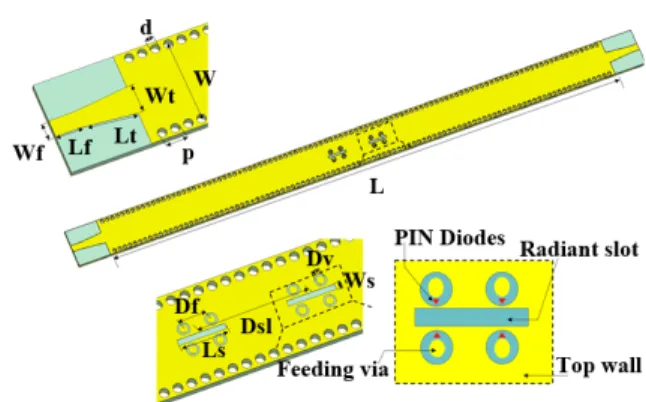
FIGURE 1. Details of the proposed SIW antenna array. L = 100 mm, W = 6 mm, Wt = 2.1 mm, Lt = 4.2 mm, Wf = 1.27 mm, Lf = 1.9 mm, d = 0.7 mm, p = 1mm, Dsl = 8 mm, Ls = 3.5 mm, Ws = 0.4 mm, Df = 2 mm, Dv = 0.6 mm.
feeding slots. This design is realized by introducing a new method for centered slots excitation, based on four coupling plated-through holes, which are inserted on each side of the slots. Each hole is directly connected to the ground plane and top wall as done in conventional SIW. This feeding method consists of connecting or disconnecting holes to the ground plane and top wall by pin diodes whose states can be changed between ‘‘ON’’ and ‘‘OFF’’ by bias voltage. Therefore, the phase shifts are controlled by altering the switches states, and the beam direction of the SIW antenna can be electronically steered by associating different slot configurations.
To validate the fundamental principle, a study of passive 2-element arrays is investigated. Then, the reconfigurable array is designed to achieve the electronic beam scanning ability. Measurements and simulations around 27 GHz of both passive and active antenna arrays will be presented and discussed. This solution is a promising candidate for 5G communications due to its merits of compact structure and convenient integration with differential integrated circuits.
II. ANTENNA DESIGN AND ANALYSIS
A. ANTENNA GEOMETRY
The scheme of the proposed slotted SIW structure is shown in Fig. 1.On the top surface, two centered slots are etched as radiation elements, the length of the slots Ls is about 0.44λg and the distance Dsl that separates the slots is equal to λg. At the outer corners of each slot are linked with four 0.9mmdiameter-isolated plated-through holes, which are used as the feeding system. They are arranged to connect the top conductor and the ground as in conventional SIW, in order to separately control the switching of the slot feeds.
As shown in Fig. 1, four pin diodes are connected on each PTH for radiation pattern reconfigurability. The pin diodes are MA4AGBL912 from Macom with low series resistance of 4 , low capacitance of 28 fF, and an extremely fast switching speed of 5ns.
A microstrip to SIW transition with a length of Lt +
Lf and a width being linearly tapered from Wt to Wf was also designed to feed this antenna as illustrated in Fig. 1. Simulations are performed using CST microwave studio time
FIGURE 2. Two different slot array configurations with single and double excitation with their phase distribution at 26.75 GHz, for: (a)1φ = 0◦, (b)1φ = 225◦.
domain solver. The proposed leaky-wave antenna (LWA) is designed on a Roger 3003 substrate with a thickness of h = 0.5 mm, dielectric constant of εr = 3 and a loss tangent of tanδ = 0.0013 at 27 GHz.
B. SLOT FEEDING: PLATED-THROUGH HOLES METHOD
This method of excitation using plated-through holes is inspired essentially from the classic feeding method based on probes inserted in the middle of the slots. The only difference is the number and location of the metalized via holes. The arrangement proposed in this article allows different slot excitations to control the EM wave. It is also an approach for introducing a fixed amount of phase shift in an SIW structure [16]. As shown in Fig. 1, each slot is fed by four metalized vias holes which disturb the incident signal flow, the spacing between these feeding vias was fixed atλg/ 4, and each vias position is used to feed the central slot with a given phase shift. In this design, the adjacent PTH are controlled by pin diodes, which in turn achieves the ability of switching in the SIW technology [17], by connecting or isolating the holes simultaneously from the ground plane and top wall of the waveguide by changing the states of the pin diodes. When the all diodes are turned OFF, there is no effect on the impedance of the SIW and the incident signal is transmitted. But in case of turning ON the diodes, the incident signal is reflected back by the PTH inside the waveguide channel. Thus, this allows a new feeding method for the centered slots by controlling the electrical phase shifts.
To control the electrical phase shifts 1φ, different slot configurations fed by single or double excitation are studied. The electrical phase shifts 0◦, 90◦, 180◦and 270◦require a single PTH excitation slot, however, to reach1φ = −45◦, + 45◦and 225◦two PTH excitations are required. As described in Fig. 2(a), the two centered slots have the same phase distri-bution with single PTH excitations (1 and 5), which mean no phase shift is introduced1φ = 0◦. While in Fig. 2(b), the first slot is excited by only the PTH number 1, but the second one is fed by double excitation (6 and 7). The phase distribution at each slot is different (represented by different colors), thus resulting in an overall1φ of 225◦. Therefore, by changing the
vias feeding position we can control the phase of the elements of the array.
C. ANGULAR BEAM TILT PRINCIPLE
A detailed study of 2-element array configurations is carried out in order to study and validate this angular beam-tilting approach. Each centered slot is fed by at least one metalized
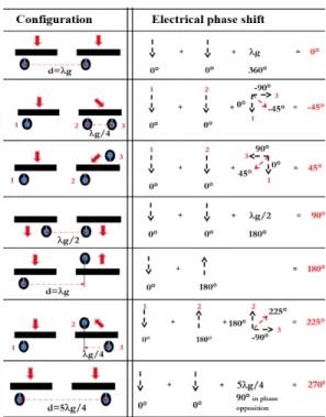
FIGURE 3. Slot configurations and associated phase shifts.
via hole located directly on its edge. For controlling the desired angular beam tilts, the distance between central slots and feeding vias are kept constant, and the slot associations are determined based on the appropriate slot configurations as explained previously. To validate theoretical beam tilts, which can be approximately expressed by:
θ0= −arcsin(1φ ∗ λ0÷2πd) (1)
whereθ0 refers to the theoretical beam tilt,1φ is the
elec-trical phase shift and d is the distance between the slots. Fig. 3 shows different association of slots, with all config-urations fed by single or double excitation, to control the electrical phase shifts with an offset of 45◦.
For1φ = 180◦, an association of two slots are fed differ-ently and spaced byλg (i.e. corresponding to 1φ = 360◦); the first one is fed from below, and the second from the top, to get the physical phase opposition which corresponds to 1φ = 180◦. Furthermore,1φ = 0◦ is the association of
two slots fed by the same way, from the bottom right side and always spaced byλg.
To obtain1φ = 0◦, 90◦, 180◦ and 270◦, only one exci-tation per slot is required. To obtain1φ = 45◦, −45◦and
225◦, different associations based on double excitations are
described in Fig. 3.
In designing a two slot array, the positions, number of excitations per slot, and the distance between feeding vias, changes the current distribution, and the resulting electrical phase shift. A single excitation allows a single electric field, against the field radiated by a double excitation which is a field resulting from the two excitations as depicted in Fig. 3. This proposal validates the principle of getting different beam-tilts, by essentially switching the slot associations, without using millimeter waves phase shifters. A recent study
FIGURE 4. Simulated and measured S-Parameters of passive array with phase shift +45◦.
using the same fixed frequency beam scanning principle applied to a 2 × 6 array antenna operating in C-band was reported in [18], which demonstrates a beam-scanning range of 25◦(from 34◦to 59◦). The main advantage of this work is
that it’s based on fewer radiating elements, and has a wider beam scanning range of 66◦(from −33◦to +33◦).
III. PASSIVE SIW ANTENNAS
Seven passive SIW antenna arrays (2 × 1) operating around 27 GHz are designed and fabricated, based on physical short circuit without using active components such as pin diodes or varactors, to test and validate the principle of design. S-parameters and radiation patterns are presented and discussed in detail.
A. S-PARAMETERS
Both measured and simulated S-parameters of passive array with a phase shift of +45◦are reported in Fig. 4. It indicates that the slot arrays present a good matching with a measured |S11|over the frequency range from 26.25 GHz to 27.2 GHz.
The measured magnitude of S21 parameter was close to −11 dB at 26.75 GHz, while the simulated value is around −7.5 dB. This S21difference can be due to the use
of two Ka connectors, 1092-01A-6 [Southwest Microwave], with insertion losses around 0.8dB/connector around 27 GHz, and also measurement uncertainty (e.g. misconnection) that were not included in the simulation.
B. RADIATION PATTERNS
The simulated and measured radiation patterns of the seven passive arrays (2 × 1) configuration are shown in Fig. 5. All results have been verified at a fixed frequency of 26.75 GHz. Figs. from 5(a) to 5(g) show the simulated and measured H plane (xz plane) far-field radiation patterns of the SIW antenna at 26.75 GHz. These patterns show that the beam can scan from −33◦ to +33◦with a discrete offset of 8◦, when the slot configurations are changed by isolating or bypass-ing the slot excitations. However, the LWA cannot radiate effectively when all PTH are isolated, because of the centered slots being not excited. Therefore, only the far-field patterns of the LWA fed with double excitations are provided in Fig. 5(b), 5(c) and 5(g) for directing the beam to −8◦, +8◦ and +23◦, respectively. Figs. 5(a), 5(d) to 5(f) show the
I. Serhsouh et al.: Reconfigurable SIW Antenna for Fixed Frequency Beam Scanning and 5G Applications
FIGURE 5. Simulated and measured H-plane of passive arrays with associated phase shifts at 26.75 GHz. a)1φ = 0◦, b)1φ = 45◦, c) 1φ = −45◦, d)1φ = 90◦, e)1φ = −90◦, f)1φ = 180◦, g)1φ = 225◦.
far-field radiation patterns of the H plane at 26.75 GHz fed with single excitation per slot. These patterns show that the beam can shift from 0◦to −/+15◦and −/+33◦, which corre-spond to1φ = 0◦, +/−90◦, and 180◦respectively. As shown in Fig. 6, the directivity level is about 8-9 dBi for almost all configurations, but the gain depends on the adaptation (the maximum gain is 7 dBi).
Due to the delay and the limited number of elements, about half of the energy is lost on port 2 with a radiation efficiency ranging from 30% to 65%.
It worth mentioning that the electric fields of the radiated waves are parallel to y-axis, because the proposed LWA is uniform in geometry and the radiation pattern is mainly generated by the slots fed by PTH. The cross-components are not described in Fig. 5, because of their level(below −14 dBi) for all the configurations, which is acceptable for this type of antenna.
Reasonable agreement is obtained between simulated and measured results although Ka connectors have not been taken into account in the simulation which can cause some addi-tional diffraction.
These passive antennas are designed only to validate the basic principle. This will be the basis of a compact and recon-figurable antenna design solution, which will be proposed in the next section.
FIGURE 6. Directivity and Gain levels for different passive 2 × 1 SIW antenna arrays with the radiation efficiency curve at 26.75 GHz.
IV. PROPOSED RECONFIGURABLE SIW ANTENNA
A. BIASING CIRCUIT
As illustrated in Fig. 7, the radiating elements are located on the lateral face, whereas, the biasing circuit is located on the rear face.
The facility of integration of active components is one of the advantages of SIW technology. By using the two faces of the structure, the upper face which contains the radiat-ing elements; each slot has four excitation vias crossradiat-ing the structure in height. Each PTH is loaded with a pair of pin diodes from the top and bottom, which also means that each
FIGURE 7. Exploded view of the proposed reconfigurable 2 × 1 SIW antenna array.
FIGURE 8. Photograph of the fabricated array antenna. (a) Prototype overview. (b) Front view. (c) Back view.
pin diode located in the lower face is polarized by a bias voltage Vi (i = 1, 2 . . . 6) as depicted in Fig. 8. The DC supply is connected directly through the conventional holes of the SIW structure. They are connected to the feeding vias by quarter wave-lines on the lower face to feed the pin diodes by coupling on both layers. The ground is taken directly from the lower face which contains the biasing circuit with one coupling capacitor SLC ‘‘single layer capacitor’’ and quarter wave line for each pair of pin diodes, these lines are short-circuited via the grounded capacitors, and return an open circuit to isolate the RF signal from the biasing circuit. This solution aims to ensure the compactness and minimizing the influence of the active components on the antenna radiation. To validate the presented design strategy, as depicted in Fig. 8, an LWA based on SIW technology for beam scanning at fixed frequency is fabricated and measured. The S-parameters of the proposed 2 × 1 array are simulated using CST Microwave studio and measured by the vector network analyzer ‘‘Keysight technologies N5222A’’.
B. S-PARAMETERS
The measured and simulated S-parameters are shown in Fig. 9. Simulated and measured reflection coefficients mag-nitude are lower than −12 dB from 26.2 GHz to 27.3 GHz. The radiation efficiency of this antenna varies between 60% and 94%, depending on the chosen excitation configurations. For the case of the slotted array with1φ = 270◦as shown in
FIGURE 9. Simulated and measured S-Parameters of array configuration with phase shift 270◦.
FIGURE 10. Simulated and measured radiation patterns of reconfigurable SIW antenna arrays at 27.25 GHz for1φ = 0◦and1φ = 180◦.
Fig. 9, the measured radiation efficiency exceeds 90% with |S21| = −12.86 dB at 27.25 GHz.
The measured and simulated results of reflection and transmission coefficients are in good agreement. A matching impedance corresponding to magnitude of |S11|< −10 dB around 27 GHz is obtained. The discrepancy between the sim-ulated and measured results is probably due to the integration of the biasing circuit which is not taken into account in the simulation.
C. RADIATION PATTERNS
Two array configurations, corresponding to1φ = 0◦ and 1φ = 180◦, are selected as an example to see the efficiency
of the fabricated antenna.
Fig. 10 represents the simulated and measured far-field radiation patterns of the H plane, which correspond to1φ = 0◦and1φ = 180◦. These patterns show that the beam can scan 0◦and +/−33◦, respectively at 27.25 GHz.
Measurements have a good agreement with the simula-tions. A small shift in operating frequency of 0.5GHz is noticed between the passive and active antennas, this may be due to the integration of the active components, but even this new operating frequency is fine for the application.
V. CONCLUSION
A fixed-frequency beam-scanning reconfigurable LWA based on SIW structure was presented at an operating frequency of around 27 GHz. The ability to beam-scan is achieved by
I. Serhsouh et al.: Reconfigurable SIW Antenna for Fixed Frequency Beam Scanning and 5G Applications
exciting the slot configurations electrically, fed with plated-through holes (PTH). The SIW is designed with two slots fed by plated-through holes technology, and via feeding are connected to the ground plane and top wall through binary switches. By switching the pin diode states ‘‘low loss or iso-lation’’ using respectively +10mA or 0V to ensure the bias conditions; the array configuration and the corresponding beam direction can be changed electronically. Finally, differ-ent passive antenna prototypes are simulated and measured to validate this principle, based only on physical short circuits instead of using pin diodes for controlling the array configu-rations. Verified experimentally, the beam can be steered from −33◦to +33◦in discrete steps of 8◦. The directivity can be improved by increasing the number of radiating elements.
REFERENCES
[1] Y. Cao, Y. Cai, L. Wang, Z. Qian, and L. Zhu, ‘‘A review of sub-strate integrated waveguide end-fire antennas,’’ IEEE Access, vol. 6, pp. 66243–66253, 2018.
[2] G. Venanzoni, D. Mencarelli, A. Morini, M. Farina, and F. Prudenzano, ‘‘Review of substrate integrated waveguide circuits for beam-forming networks working in X-Band,’’ Appl. Sci., vol. 9, no. 5, p. 1003, 2019. [3] F. Xu and K. Wu, ‘‘Guided-wave and leakage characteristics of substrate
integrated waveguide,’’ IEEE Trans. Microw. Theory Techn., vol. 53, no. 1, pp. 66–73, Jan. 2005.
[4] Y. Mohtashami and J. Rashed-Mohassel, ‘‘A butterfly substrate integrated waveguide leaky-wave antenna,’’ IEEE Trans. Antennas Propag., vol. 62, no. 6, pp. 3384–3388, Jun. 2014.
[5] L. Wu, A. J. Farrall, and P. R. Young, ‘‘Substrate integrated waveguide switched beam antenna,’’ IEEE Trans. Antennas Propag., vol. 63, no. 5, pp. 2301–2305, May 2015.
[6] Y. Li and Y. Li, ‘‘Investigation on SIW slot antenna array with beam scanning ability,’’ Int. J. Antennas Propag., vol. 2019, pp. 1–7, Jan. 2019. [7] Y.-Q. Wen, B.-Z. Wang, and X. Ding, ‘‘Wide-beam SIW-slot antenna for wide-angle scanning phased array,’’ IEEE Antennas Wireless Propag. Lett., vol. 15, pp. 1638–1641, 2016.
[8] Y. J. Guo and P.-Y. Qin, ‘‘Reconfigurable antennas for wireless com-munications,’’ in Handbook of Antenna Technologies, Z. N. Chen, D. Liu, H. Nakano, X. Qing, and T. Zwick, Eds. Singapore: Springer, 2016, pp. 2987–3032.
[9] N. Ojaroudi Parchin, H. Jahanbakhsh Basherlou, Y. Al-Yasir, R. Abd-Alhameed, A. Abdulkhaleq, and J. Noras, ‘‘Recent developments of reconfigurable antennas for current and future wireless communication systems,’’ Electronics, vol. 8, no. 2, p. 128, 2019.
[10] J. Zhang, S. Zhang, X. Lin, Y. Fan, and G. Pedersen, ‘‘3D radiation pattern reconfigurable phased array for transmission angle sensing in 5G mobile communication,’’ Sensors, vol. 18, no. 12, p. 4204, 2018.
[11] M. Frank, F. Lurz, R. Weigel, and A. Koelpin, ‘‘Electronically recon-figurable 6×6 element transmitarray at K-band based on unit cells with continuous phase range,’’ IEEE Antennas Wireless Propag. Lett., vol. 18, no. 4, pp. 796–800, Apr. 2019.
[12] K. Chen, Y. H. Zhang, S. Y. He, H. T. Chen, and G. Q. Zhu, ‘‘An electron-ically controlled leaky-wave antenna based on corrugated SIW structure with fixed-frequency beam scanning,’’ IEEE Antennas Wireless Propag.
Lett., vol. 18, no. 3, pp. 551–555, Mar. 2019.
[13] Y. Geng, J. Wang, Y. Li, Z. Li, M. Chen, and Z. Zhang, ‘‘Radia-tion pattern-reconfigurable leaky-wave antenna for fixed-frequency beam steering based on substrate-integrated waveguide,’’ IEEE Antennas
Wire-less Propag. Lett., vol. 18, no. 2, pp. 387–391, Feb. 2019.
[14] R. Ranjan and J. Ghosh, ‘‘SIW-based leaky-wave antenna supporting wide range of beam scanning through broadside,’’ IEEE Antennas Wireless
Propag. Lett., vol. 18, no. 4, pp. 606–610, Apr. 2019.
[15] J.-P. Zhang, B. Li, and Z.-P. Zhou, ‘‘A substrate integrated waveguide slot antenna for 79-GHz applications,’’ in Proc. Int. Workshop Antenna
Technol. (iWAT), Mar. 2018, pp. 1–3.
[16] B. T. Malik, V. Doychinov, and I. D. Robertson, ‘‘Compact broadband elec-tronically controllable SIW phase shifter for 5G phased array antennas,’’ in Proc. 12th Eur. Conf. Antennas Propag., Apr. 2018, pp. 1–5.
[17] I. Lim and S. Lim, ‘‘Substrate-integrated-waveguide (SIW) single-pole-double-throw (SPDT) switch for X-band applications,’’ IEEE Microw.
Wireless Compon. Lett., vol. 24, no. 8, pp. 536–538, Aug. 2014. [18] T. Lou, X.-X. Yang, H. Qiu, Q. Luo, and S. Gao, ‘‘Low-cost electrical
beam-scanning leaky-wave antenna based on bent corrugated substrate integrated waveguide,’’ IEEE Antennas Wireless Propag. Lett., vol. 18, no. 2, pp. 353–357, Feb. 2019.
IMANE SERHSOUH was born in Mohamme-dia, Morocco, in 1991. She received the M.S. degree in electronic and telecommunications from Abdelmalek Essaadi University, Tetouan, Morocco, in 2014. She is currently pursuing the Ph.D. degree with the Faculty of Sciences and Techniques of Mohammedia, University of Hassan II Casablanca, Morocco. Her research interests include SIW antennas and design of electronicbeam-scanning array antennas. MOHAMED HIMDI received the Ph.D. degree in signal processing and Telecommunications from the University of Rennes1, France, in 1990. Since 2003, he has been a Professor with the University of Rennes 1, and the Head of the High Frequency and Antenna Department until 2013, of IETR. He has authored or coauthored 138 journal articles and over 280 articles in conference proceedings. He has also coauthored nine book chapters. He holds 41 patents. His research activities concern passive and active millimeter-wave antennas. His research interests include devel-opment of new architectures of antenna arrays, and new three-dimensional (3-D) antenna technologies. He was Laureate of the 2d National Competition for the Creation of Enterprises in Innovative Technologies, in 2000 (Ministry of Industry and Education). In March 2015, he received the JEC-AWARD at Paris on Pure composite material antenna embedded into a motorhome roof for the Digital Terrestrial Television reception.
HASSAN LEBBAR received the Ph.D. degree in signal processing and telecommunications from the University of Rennes 1, Rennes, France, in 1994. He is currently a Professor of higher education with the Electrical Engineering Depart-ment, Faculty of Sciences and Techniques of Mohammedia (FSTM), University Hassan II Casablanca, Morocco. His research interests are curved printed antennas and integrated substrate waveguide array antennas.
HAMSAKUTTY VETTIKALLADI received the Ph.D. degree from the Cochin University of Sci-ence and Technology, and the Habilitation A Diriger des Recherches degree from the Univer-sity of Rennes 1, France, in 2018. He started his carrier as a Postdoctoral Researcher with the Bell Engineering Department, University of Arkansas, USA, in January 2008, just after fin-ishing his Ph.D. degree. From 2008 September to 2012 November, he was working as a Postdoctoral Fellow with the Institute of Electronics and Telecommunication of Rennes, University of Rennes, France. He was an Assistant Professor with King Saud University, from November 2012 to December 2017. He has been an Asso-ciate Professor with the Department of Electrical Engineering, King Saud University, since January 2018. He is the author of more than 85 scientific publications in international journals and conferences and three book chapter. His main research focus includes microwave, millimeter and THz antenna design for various applications, including high speed WIFI, automotive radar, imaging, point to point communication, 5G, and so on. He has served as a Visiting Faculty in several institutes, as an editor and a referee in several scientific journals and conferences.