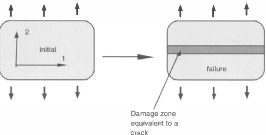
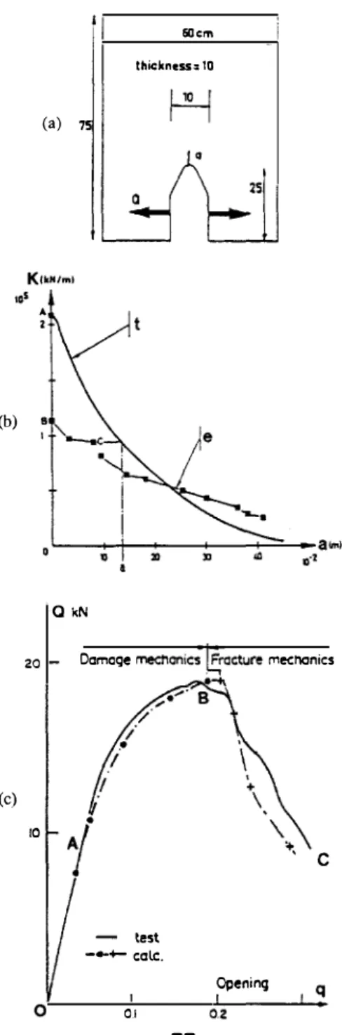
Bridges between Damage and Fracture Mechanics
Texte intégral
Figure
Documents relatifs
The skin, an easily accessible organ, allows clinicians to quickly evaluate the peripheral tissue perfusion with noninvasive bedside parameters such as the skin tem-
[r]
Lecture : 76 % des établissements ayant recruté sur un poste de cadre déclarent que le fait que le besoin était limité dans le temps est une raison importante ou très importante
(I), and that the plastic deformation observed in the fractography of tempered specimens provided the necessary condition for the deformation induced phase transformation, it may
This result shows that a model accounting for an anisotropic behavior is necessary to achieve the identification of all the material parameters (in particular the elastic
consistent with the 2-bar model prediction and both suggest that the test at 750 C is not in the creep constrained cavity growth region, since an extrapolation
One can see on this figure that the microstructure has a slight influence (less than 4 %) on the peak strength value of our concrete. The macroscopic tensile strength is mainly
In the present work, a meso-scale analysis of the tensile splitting test was used to in- vestigate the size effect on the nominal stress at failure σ N and to determine the
![Compte rendu : Laurence Arrighi et Annette Boudreau (dir.) (2016), Langue et légitimation : la construction discursive du locuteur francophone, Québec, Presses de l’Université Laval, coll. « Les Voies du français », 235 p. [ISBN : 978-2-7637-3174-2]](data:image/gif;base64,R0lGODlhAQABAIAAAP///wAAACH5BAEAAAAALAAAAAABAAEAAAICRAEAOw==)