HAL Id: hal-02343877
https://hal-centralesupelec.archives-ouvertes.fr/hal-02343877
Submitted on 11 Mar 2020
HAL is a multi-disciplinary open access
archive for the deposit and dissemination of
sci-entific research documents, whether they are
pub-lished or not. The documents may come from
teaching and research institutions in France or
abroad, or from public or private research centers.
L’archive ouverte pluridisciplinaire HAL, est
destinée au dépôt et à la diffusion de documents
scientifiques de niveau recherche, publiés ou non,
émanant des établissements d’enseignement et de
recherche français ou étrangers, des laboratoires
publics ou privés.
Designing Carrier Selective Perovskite on Silicon 3T
Tandems
J.P. Connolly, Jean-Paul Kleider, Marie-Estelle Gueunier-Farret, Zakaria
Djebbour, J Alvarez, Denis Mencaraglia, M. K. Nazeeruddin, Valentin
Mihailetchi, Philippe Baranek, Philip Schulz, et al.
To cite this version:
J.P. Connolly, Jean-Paul Kleider, Marie-Estelle Gueunier-Farret, Zakaria Djebbour, J Alvarez,
et al..
Designing Carrier Selective Perovskite on Silicon 3T Tandems.
36th European
Pho-tovoltaic Solar Energy Conference and Exhibition, WIP, Sep 2019, Marseille, France.
pp.779,
�10.4229/EUPVSEC20192019-3BV.2.60�. �hal-02343877�
DESIGNING CARRIER SELECTIVE PEROVSKITE ON SILICON 3T TANDEMS
J.P. Connolly1a, J.P. Kleider1, M.E. Gueunier-Farret1, Z. Djebbour1,8, J. Alvarez1, D. Mencaraglia1, M.K. Nazeeruddin2, V. Mihailetchi3, P. Baranek4,5, P. Schulz5,6, O. Isabella7 1 GeePs, LGEP, UMR CNRS 8507, Supelec, Université Pierre et Marie Curie, Université Paris-sud,
11 rue Joliot-Curie, 91192 Gif-sur-Yvette, France
2 Group for Molecular Engineering of Functional Materials, Department of Chemistry and Chemical Engineering, Swiss Federal Institute of Technology, CH-1951 Sion, Switzerland
3 ISC Konstanz e.V., Rudolf-Diesel-Straße 15, Konstanz 78467, Germany
4 EDF R&D, Dept. EFESE, EDF Lab Paris-Saclay, 7 boulevard Gaspard Monge, 91120 Palaiseau, France 5 IPVF, 30 route Départementale 128, 91120 Palaiseau, France
6 CNRS, IPVF, UMR 9006, 30 route Départementale 128, 91120, Palaiseau, France 7 Delft University of Technology, PVMD Group, Mekelweg 4, 2628 CD Delft, The Netherlands
8UVSQ, Université Paris-Saclay, 45 Avenue des Etats Unis, 78035 Versailles cedex, France
ABSTRACT: We explore design criteria for a new multijunction solar cell concept, the three terminal selective band offset barrier solar cell (3T-SBOB). The 3T-SBOB reaches tandem solar efficiencies without suffering from series current constraints of two terminal designs, and without suffering from grid alignement issues of four terminal designs. It consists of a low bandgap silicon interdigitated back contact solar cell, connected to a high bandgap top cell by a selective band offset barrier (SBOB). The SBOB allows transport of only one type of charge carrier, leading to independent quasi-Fermi level separations in top and bottom cells under illumination It reaches tandem efficiencies with three terminals and with technical advantages over 2T and 4T devices. This paper reports results of the design of the 3T-SBOB device. Two candidate materials for this critical ETL and SBOB material are SnO2 and PC(71)BM. This paper presents these preliminary materials studies and resulting device structures which will be evaluated in a forthcoming H2020 Solar-ERANET project (BOBTANDEM) the kick-off of which coincides with this conference. Keywords: Multijunction ; Silicon ; Perovskite ; High efficiency ; Novel device
Author for correspondence : james.connolly@geeps.centralesupelec.fr
1 INTRODUCTION
Multi-junction devices lead progress in high efficiency solar cell designs. However, the conceptually attractive two terminal and four terminal multijunction devices suffer respectively from series current constraints and from grid alignment design issues.
This paper introduces a new ERANET project BOBTANDEM which is developing a new concept, the three terminal (3T) carrier selective band offset barrier (SBOB) tandem solar cell [1]. This design is based on a silicon interdigitated back contact solar cell [2], on top of which is grown the SBOB layer. The cell is completed by a high bandgap perovskite solar cell with a single front surface contact. The design prevents thermalisation of top cell majority carriers in the bottom cell, while allowing photogenerated carriers of one polarity in the top cell to be collected in the bottom cell. This results in independent quasi-Fermi level separations in top and bottom cells, and independent current-voltage curves. The 3T-SBOB tandem is a structure yielding tandem efficiencies from two independently operating subcells, with advantages over 2T and 4T designs.
We use numerical modelling applied to study the performance of the 3T-SBOB device. The structure we focus on is based on an n-type silicon interdigitated back contact (IBC) bottom cell. The top cell is a perovskite solar cell (PSC) with an organic [3] front surface hole transport layer (HTL), a standard perovskite absorber, which is connected to the IBC by an electron transport layer (ETL) playing the role of SBOB. Two candidate materials for this critical ETL and SBOB material are SnO2 [4] and PC(71)BM [5].
Figure 1: Three terminal band offset barrier structure
showing two independent operating circuits for top and bottom cells for the case of an n-type IBC bottom cell.
2 DISCUSSION 2.1 Efficiency limits
We start by examining the radiative efficiency limit. In the 3T-SBOB, the two subcells operate at independent current and voltage, similar to a 4T design. The 3T-SBOB is therefore subject to the same radiative 7 efficiency limit as a 4T.
To put the 3T-SBOB in context, figure 2 shows the radiative efficiency limits of the 2T tandem for reference and the 3T-SBOB tandem in the Shockley-Queisser 30% efficiency configuration [shockley-queisser] which does not include a back mirror.
The first point which stands out is the much broader efficiency maximum for the 3T-SBOB relative to the 2T. This is a reflection of the elimination of the series current
constraint.
The second point is the slightly higher efficiency maximum. This is an interesting and non-trivial consequence of loss of series power constraint which is independent of the form of the spectrum and instead due to the maximum power point operation of each cell as opposed to the 2T design which imposes constant current. This is linked to superior minimisation of thermalisation losses in the 3T-SBOB (and 4T) designs.
The conclusion of this brief introductory investigation of efficiency potential is that the 3T-SBOB slightly exceeds the current constraint limited 2T design (fig. 2b). There is furthermore an obviuos design advantage in that the significantly broader efficiency contour of the 3T-SBOB design compared to the 2T design.
Figure 2 Comparison of ideal efficiency profiles for (a)
series constrained two terminal tandems cells and (b) independently operating SBOB tandem cells. The 3T-SBOB cell shows a broader efficiency contour with a slightly higher maximum effiicency than 2T cells.
Table 1: Idealised cell materials parameters
Material Affinity (eV) Bandgap (eV)
ETL - SBOB 4.05 3.7
Perovskite 4.05 1.7
HTL 3.8 4.02
2.2 Idealised prototype
Preliminary evluation of the 3T-SBOB has been presented previously [9] and is summarised here to sketch the operational principles of the 3T-SBOB. The silicon solar cell IBC modelling uses well established materials and design parameters [8]. However moving on from [9] we use here idealised but achievable PSC cell materials parameters [6] including perfect affinity matching and a broadly ideal Perovskite bandgap. This approach using idealised but physically realistic materials parameters enables us to propose reaching efficiencies of 35%, which is significantly less than the ideal efficiency limit of above 42% in our 3T-SBOB configuration.
Figure 3 Numerical band structure calculation of
the three terminal band offset barrier solar cell band structure with both cells at maximum power voltage. The different separation of quasi-Fermi levels in top cell perovskite cell and bottom IBC silicon cell.
2.3 SBOB operation
Figure 3 shows a numerical simulation of 3T-SBOB band structure under 1 sun AM1.5G including hole and electron qusi-Fermi levels in top and bottom cell. The bottpm Si-IBC cannot be shown on the same scale and extends 180µm to the left, as indicated by the dotted arrows on the figure.
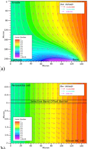
One can clearly see the greater quasi-Fermi level separation in the top cell compared to the silicon IBC. The top cell therefore operates between the front contact and the IBC n+ back contact at a potential determined by the top cell bandgap, while the independent lower bandgap bottom cell operates at a potential determined by its bandgap. The structure is therefore subject to the same efficiency limit as a four terminal cell with independent top and bottom cell current-voltage characteristics. Figure 4 shows numerical modelling of current flows in
(b)
(a)
the whole structure. This shows the electron current flowing from the top PSC (not visible at this scale) to bottom IBC. In the bottom cell we also see an electron current flowing from the cathode to the base (where the name is chosen for convenience by analogy with transistors).
Figure 4b shows the hole current for a zoom on the interface region. This demonstrates in detail the operation of the SBOB layer repelling holes from the top cell and preventing their thermalisation in the bottom cell. Not shown for brevity is the electron current on the same scale as figure 4b which would simply show parallel and uniform electron flow-lines flowing from top to bottom, that is, in the opposite direction to the current flowlines of figure 4a.
It is these flowlines which, together with the band diagram of figure 3, which show the operational principles of this design.
Figure 4 Current flows under AM1.5G illumination: (a)
Total current over the whole device; (b) focus on the interface region showing the hole current blocked by the SBOB
3 CONCLUSION
The brief and preliminary work presented here is the design stage before the start of an H2020 ERANET project BOBTANDEM. This project will investigate the materials sketched in table 1 while applying materials modelling from ab initio to device modelling scales to optimise materials both from the materials properties and
materials compatibility (growth) directions. A number of materials have been proposed and will be reported as the poject progresses over the next three years.
Since the project is based on well advanced IBC and PSC cells, both of which are in the process of industrialisation, the project will include a significant activity in optical modelling for design of real devices, and annual yield modelling.
Acknowledgements : The authors acknowledge the
support of the COST Association through project MultiscaleSolar, the H2020 program, and the ANR French national funding agency, which have allowed the preliminary exchanges leading to the ERANET project BOBTANDEM (2019-2022).
References
[1] Z. Djebbour et al., “Bandgap engineered smart
three‐terminal solar cell: New perspectives towards very high efficiencies in the silicon world”, Prog
Photovolt Res Appl. 27, 4 pp. 306-315 (2019);
http://dx.doi.org/10.1002/pip.3096
[2] A. Halm, V.D. Mihailetchi, et al., “The Zebra Cell
Concept - Large Area n-Type Interdigitated Back Contact Solar Cells and One-Cell Modules Fabricated Using Standard Industrial Processing Equipment”, 27th EU-PVSEC (2012)
http://dx.doi.org/10.4229/27thEUPVSEC2012-2AO.2.1
[3] R. Shang, et al., “Disodium Benzodipyrrole Sulfonate
as Neutral Hole- Transporting Materials for Perovskite Solar Cells”, J. Am. Chem. Soc., (2018),
140, 5018-5022.
[4] Alex M. Ganose and David O. Scanlon, “Band gap
and work function tailoring of SnO2 for improved transparent conducting ability
in photovoltaics”, . Mater. Chem. C, 2016, 4, 1467
(2016)
[5] Eric T. Hoke et al., “The Role of Electron Affinity in
Determining Whether Fullerenes Catalyze or Inhibit Photooxidation of Polymers for Solar Cells”, Adv.
Energy Mater. (2012), 2, 1351–1357
[6] Materials database and references therein :
https://refractiveindex.info/?shelf=other&book=CH3 NH3PbI3&page=Phillips
[7] W. Shockley, H. J. Queisser, ’Detailed balance limit of efficiency of p-n junction solar cells’ Journal of Applied Physics, 32, 510. doi:10.1063/1.1736034, 1961
[8] C. Chaverri Ramos, L. Bellières, J.P. Connolly, J. Ayucar, G. Sánchez, “Efficiency Enhancement in
Plasmonic IBC Solar Cells”, 27th EUPVSEC (2012)
http://dx.doi.org/10.4229/27thEUPVSEC2012-1BV.8.8
[9] Jean-Paul Kleider et al., “Three-terminal tandem
solar cells combining bottom interdigitated back contact and top heterojunction subcells: a new architecture for high power conversion efficiency”,
35th EUPVSEC (2012)
http://dx.doi.og/10.4229/35thEUPVSEC20182018-1AO.2.4