Technology researchers and makes it freely available over the web where possible.
This is an author-deposited version published in: https://sam.ensam.eu Handle ID: .http://hdl.handle.net/10985/7458
To cite this version :
Annie-Claude BAYEUL-LAINE, Patrick DUPONT, Giovanna CAVAZZINI, Patrick CHERDIEU, Gérard BOIS, Antoine DAZIN, Olivier ROUSSETTE - NUMERICAL AND EXPERIMENTAL
INVESTIGATIONS IN A VANED DIFFUSER OF SHF IMPELLER: FLUID LEAKAGE EFFECT - In: Congrès français de mécanique (21 ; 2013 ; Bordeaux (Gironde))., France, 2013-11-26 - Congrès français de mécanique (21 ; 2013 ; Bordeaux (Gironde)). - 2013
1
NUMERICAL AND EXPERIMENTAL INVESTIGATIONS
IN A VANED DIFFUSER OF SHF IMPELLER: FLUID
LEAKAGE EFFECT
A. C.BAYEUL-LAINEa, P. DUPONTb, G. CAVAZZINIc, P. CHERDIEUb, A. DAZINa , G. BOISa,
O. ROUSSETTEg
a. Arts et Métiers PARISTECH, LML, UMR CNRS 8107, Bd Paul Langevin, 59655 VILLENEUVE D’ASCQ b. Ecole Centrale de Lille, LML, UMR CNRS 8107, Bd Paul Langevin, 59655 VILLENEUVE D’ASCQ c.University of Padova, Energy and Fluids, Department if Industrial Engineering
Abstract
The paper presents the analysis of the performance and the internal flow behaviour in the vaned diffuser of a radial flow pump using PIV technique, pressure probe traverses and numerical simulations. PIV measurements have been performed at different heights inside one diffuser channel passage for a given speed of rotation and various flow rates. For each operating condition, PIV measurements have been made for different angular positions of the impeller. For each angular position, instantaneous velocities charts have been obtained on two simultaneous views, which allows, firstly, to cover the space between the leading edge of the impeller and the diffuser throat and secondly, to get a rather good evaluation of phase averaged velocity charts and “fluctuating rates “. Probe traverses have also been performed using a 3 holes pressure probe from hub to shroud diffuser width at different radial locations in between the two diffuser geometrical throats. The numerical simulations were realized with the two commercial codes: i-Star CCM+ 7.02.011 (at LML), ii-CFX 10.0 (at University of Padova). Fully unsteady calculations of the whole pump were performed. Comparisons between numerical and experimental results are presented and discussed for two flow rates. In this respect, the effects of fluid leakage due to the gap between the rotating and fixed part of the pump model are analysed and discussed.
Keywords:
Pump, diffuser, PIV measurements, numerical calculations, probes1 Introduction
Flow behaviour in a radial machine is quite complex and is strongly depending on rotor stator interactions and operating conditions [1-3].
In numerical simulation, two aspects have to be considered, the first one concerns the governing equations which are solved in the model: two kinds of numerical calculations are currently used in turbo machinery (i-frozen rotor calculations, ii-unsteady calculations). The second aspect concerns the geometrical model. Some geometrical simplifications are currently used. For example, the leakage flows are often neglected. It is obvious that a complex model (fully unsteady, with leakage flows) will be more time consuming but closer to the real physics. In this paper, some limits of the numerical models are pointed out. To do so, two numerical calculations are compared to experimental results for two flow rates.
The test model corresponds to the so-called SHF pump, working with air, in similarity conditions compared to water, for which several studies have been made [4-10] involving numerical and PIV comparisons. Figure 1 shows SHF impeller. The existing database has been completed by pressure probe measurements for a complete flow performance analysis. These measurements are compared to several numerical calculations in the present paper.
2 Experiments
Test pump model and PIV measurements conditions have been already described in several papers as ref [4, 5 and 6] and main pump characteristics are given in table 1. This set-up allows the existence of a “positive” leakage flow going into the gap between impeller outlet section and inlet vaned diffuser section which is specific to the experimental set-up. This is due to the fact that the pump outlet corresponds to atmospheric conditions.
The PIV results come from the thesis of G. Cavazzini [9].
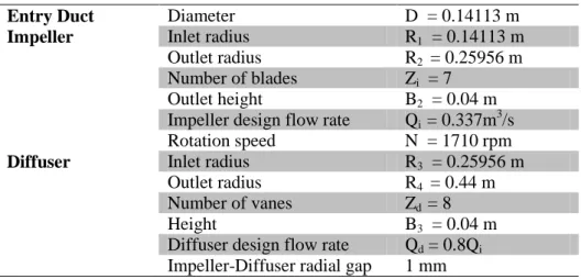
Table 1 : Pump characteristics
Entry Duct Diameter D = 0.14113 m
Impeller Inlet radius R1 = 0.14113 m Outlet radius R2 = 0.25956 m Number of blades Zi = 7
Outlet height B2 = 0.04 m Impeller design flow rate Qi = 0.337m
3 /s Rotation speed N = 1710 rpm
Diffuser Inlet radius R3 = 0.25956 m Outlet radius R4 = 0.44 m Number of vanes Zd = 8
Height B3 = 0.04 m
Diffuser design flow rate Qd = 0.8Qi Impeller-Diffuser radial gap 1 mm
2.2 Three holes probes
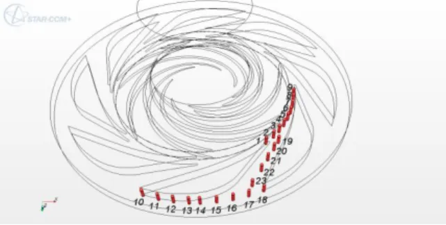
A three holes probe has been used to make hub to shroud traverses. Using a specific calibration one can get total pressure, static pressure, absolute velocity and its two components in radial and tangential direction. In order to well represent the flow field, twenty-three probe locations are defined as it can be seen in figure 1. For each location, ten axial positions are registered (b*=0.125, 0.2, 0.25, 0.375, 0.5, 0.625, 0.75, 0.875, 0.925, 0.975 from hub to shroud). The present analysis focuses only on locations 19 to 23 in the blade to blade channel of the diffuser.
2.3 General flow conditions
All types of measurements have been performed for several flow rates. But, results presented in this paper refer only to two flow rates, a one close to the design point of the vaned diffuser Q*=0.766 which is different to impeller design flow rate Q*=1 (the vaned diffuser design was chosen in order to allow an enlarge pump performance characteristic curve for low flow rates). The second normalised flow rate is equal to 1.134.
3 Calculations
Frozen rotor and unsteady calculations were performed using Star CCM+ code and results are compared with already published CFX results [7, 8].
3.1 Star CCM+
The calculation domain was divided into three zones: the inlet zone, the impeller zone and the diffuser zone. The boundary condition at the inlet consisted of a flow rate. The boundary condition at the outlet was the atmospheric pressure (0 Pa). The fluid (air) was considered incompressible at a constant temperature of 20ºC. A polyhedral mesh with prism layers is used for all calculations (5 prism layers for a total prism layer thickness of 1 mm). The target size is 3 mm and the minimum size 0,5 mm . The size of the grid is about 3. 106 cells. The SST k- turbulence model is used.
Line probes are plotted as defined in figure 1 in order to obtain all parameters (pressure, total pressure, radial, tangential and axial velocity and velocity magnitude) for different impeller angular positions relative to the diffuser vanes (Figure 2). In this paper, P3 is the only position presented and discussed.
3
the whole computational domain. A time step, corresponding to an angular rotation of 1°, has been chosen.
FIG. 1 - Diffuser measurement locations for probe traverse and unsteady calculations
FIG.2 - Impeller different angular positions relative to the diffuser vanes
3.2 CFX
In order to investigate the influence of leakage flows, numerical results obtained using CFX are also presented. G. Cavazzini et al [7, 8] proposed two kinds of unsteady simulations, with and without leakage flows. The model is described in ref [7, 8].
4 Results and comparisons
Global results of total theoretical head pump are in good agreement between EULER one dimensional approach and frozen rotor calculation. Unsteady calculation results, performed for the two non-dimensional flow rates, give the same level, as it can be seen in figure 3. One can note, figure 4, that the numerical static pressures underestimate the experimental pressure rise, whatever the numerical scheme adopted. This is particularly obvious for Q/Q*>1. At these flow rates, previous studies [8, 9, and 10] have shown a strong boundary layer detachment at the diffuser vane leading edge. The calculations may have some difficulties to predict correctly the flow behaviour in these regions and thus overestimate the losses linked with these phenomena. One can nevertheless note that the consideration of the leakages seems to improve slightly the performance prediction.
FIG.3 - Pump non-dimensional total head curve FIG.4 - Pump non-dimensional static head curve Local results are analysed for unsteady calculations, three holes probes and PIV measurements.
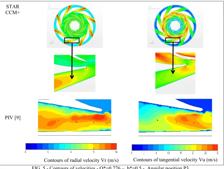
Figure 5 gives the contours of radial and tangential velocities, for b*=0.5 at mid height inside the diffuser channel passage for the angular position P3 of the impeller and for the diffuser design flow rate. The PIV experiments are compared to unsteady Star CCM+ calculations.
The radial and velocity contours at this flow rate and for the two angular positions of the impeller are very similar for the numerical results and the PIV measurements, but with a lower magnitude of velocities in case of calculation. The examination of the contours of tangential velocity for the same flow rate and for the two angular positions leads to same comments. This tendency has also been observed for other value of b* by comparison between numerical calculation and between PIV done by G. Cavazzini [9]. This leads to suppose a higher flow rate at the outlet for the case of measurements. As the experimental results have been performed with pump configuration with leakage, it can be supposed that there is a positive leakage between
impeller and diffuser. STAR
CCM+
PIV [9]
Contours of radial velocity Vr (m/s) Contours of tangential velocity Vu (m/s)
FIG. 5 - Contours of velocities - Q*=0.776 – b*=0.5 - Angular position P3 On the contrary, it has been observed, for the radial and tangential velocities contours for high flow rate that
the tendency inverses. So it can be supposed that fluid leakages are negative in this case.
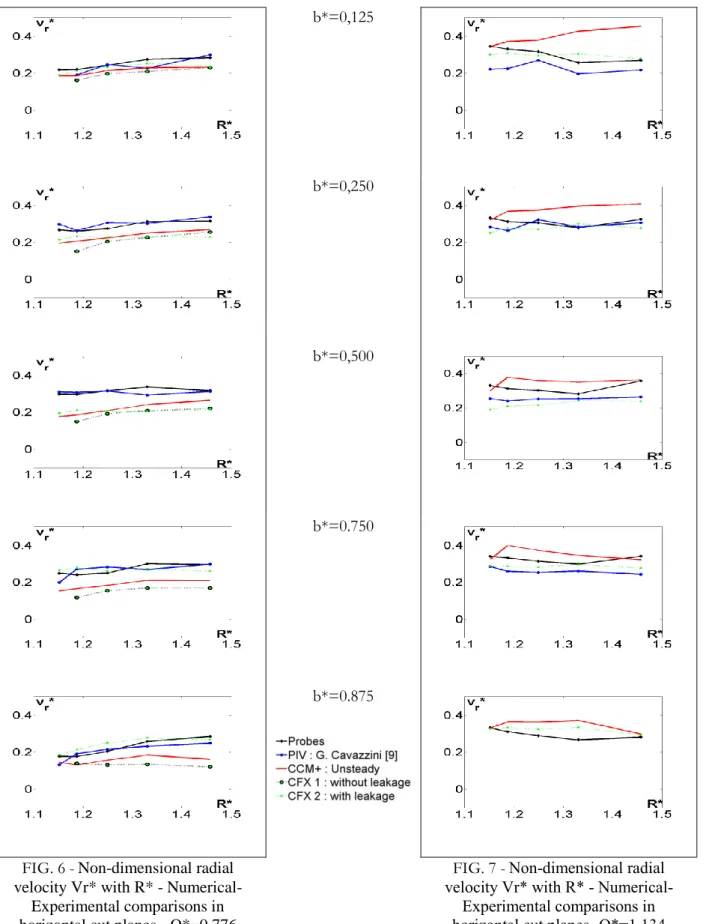
Radial velocity evolutions of unsteady calculations without leakage (obtained from the two different codes: “CCM+” and “CFX 1”), and unsteady calculations with leakage (obtained only from CFX [7]: “CFX 2”) are presented in figures 6 and 7 for both flow rates. PIV measurements (“PIV”), and three-hole pressure probes (“probes”) results are plotted on the same figures. Results present time-averaged values of radial and tangential velocities distribution from hub to shroud section as a function of radius.
The influence of leakage can be confirmed when comparing numerical results obtained without and with leakage. Experimental results are in better agreement with calculations obtained with leakage. This can be mainly seen on radial velocity distribution shown in figures 6 and 7. For Q*=0.776, the mean relative difference between experimental and unsteady calculations radial velocities is about 30% for calculations without leakage and 13% for calculations with leakage. On the contrary for Q*= 1.134 numerical results without leakage are higher than experimental ones. The mean relative difference is about -17% for calculations without leakage and 5% for calculations with leakage.
These results must be more deeply analysed, in particular PIV ones; they strongly depend on impeller position during its rotation and only time-averaged values are presented here. Pressure probe results are also depending on unsteady effects and this has to be taken into account for further data reduction analysis.
5. Conclusions
Comparisons between two numerical 3D approaches and PIV measurements have been presented inside the diffuser of a centrifugal impeller at different cut planes inside the diffuser. Two different impeller blade positions were considered. Two flow rates were studied.
5
account in order to make good comparisons between numerical and experiments.
Henceforth, simulations with fluid leakages will be realized and unsteady probes will be used in order to confirm these previous results. These calculations show few influence of taken account fluid leakage on global performance but a real improvement concerning velocity distributions.
b*=0,125
b*=0,250
b*=0,500
b*=0.750
b*=0.875
FIG. 6 -Non-dimensional radial velocity Vr* with R* -
Numerical-Experimental comparisons in horizontal cut planes - Q*=0.776
FIG. 7 -Non-dimensional radial velocity Vr* with R* -
Numerical-Experimental comparisons in horizontal cut planes- Q*=1.134
Nomenclature
b* [-] Non-dimensional distance from hub
C [mN] Impeller torque
p [Pa] Pressure
pt [Pa] Total pressure
Q* Q/Qi [m3/s] Non-dimensional volume flow rate at impeller’s inlet
Qd [m
3
/s] Diffuser design flow rate Qi [m3/s] Impeller design flow rate
R [m] Radius
R* R/R2 [-] Non-dimensional radius
Vr* vr/U2 [-] Non-dimensional radial velocity
Vu* vu/U2 [-] Non-dimensional tangential velocity
U2 R2 [m/s] Frame velocity at impeller outlet
[kg/m3] Air density
[rad/s] Angular Velocity
tc
dpt/(U22/2) [-] Non-dimensional total pump headti
CQ U22/2) [-] Non-dimensional isentropic headIndex 1 Impeller inlet
2 Impeller outlet
3 Diffuser outlet
References
[1] Adamczyk J. J., Celestina M. L., Chen J. P., 1994, « Wake induced unsteady flows :their impact on rotor performance and wake rectification », ASME International Gas Turbine and Aeroengine Congress and Exposition, The Hague, Netherlands, June 13-16, paper 94GT219.
[2] Arndt N., Acosta A.J., Brennen C.E., Caughey T.K, 1990, « Experimental Investigation of Rotor – Stator Interaction in a Centrifugal Pump With Several Vaned Diffusers », ASME Journal of Turbomachinery, Vol. 112, p. 98-108.
[3] Eisele K., Zhang Z., Casey M. V., Gülich J., Schachenmann A., 1997, « Flow analysis in a Pump Diffuser Part 1 : LDA and PTV Measurements of the Unsteady Flow », Transactions of ASME, Journal of Fluids Engineering, Vol. 119, p. 968-977.
[4] Wuibaut G., Dupont P., Caignaert G., Stanislas M., 2000, « Experimental analysis of velocities in the outlet part of a radial flow pump impeller and the vaneless diffuser using particle image velocimetry », Proceedings of the XX IAHR Symposium, Charlotte (USA), 6-9 august, paper GU-03.
[5] G. Wuibaut, G. Bois, M. El Hajem, A. Akhras, J.Y. Champagne, Optical PIV and LDV “Comparisons of Internal Flow Investigations in SHF Impeller”, Int. J. of Rotating Machinery, 1-9, 2006
[6] A. Dazin, O. Coutier-Delgosha, P. Dupont, S. Coudert, G. caignaert, G. Bois, “Rotating stall in the vaneless of a radial flow pump”, Procceedings of the 8th
iInternational Symposium on Experimental and Computational Aerothermodynamics of Internal Flows, Lyon, July 2007, paper ISAIF8-00102
[7] G. Cavazzini, P. Dupont, G. Pavesi, A. Dazin, G. Bois, A. Atif, P. Cherdieu, “Analysis of unsteady flow velocity fields inside the impeller of a radial flow pump : PIV measurements and numerical calculation comparisons”, Proc. of ASME-JSME-HSME Joint fluids engineering conference 2011, July 24-29, 2011, Hamamatsu, Japan
[8] G. Cavazzini, G. Pavesi, G. Ardizzon, P. Dupont, S. Coudert, G. Caignaert, G. Bois “Analysis of the rotor-stator interaction in a radial flow pump, Houille blanche – revue internationale de l’eau, 2009
[9] G. Cavazzini, “Experimental and numerical investigation of the rotor-stator interaction in radial turbomachines”, Ph.D. thesis, University of Padova, Padova, Italy, 2006
[10] G. Wuibaut, « Etude par vélocimétrie par images de particules des interactions roue-diffuseur dans une pompe centrifuge », PhD thesis, Thèse de Doctorat Ensam, 2001