Science Arts & Métiers (SAM)
is an open access repository that collects the work of Arts et Métiers Institute of
Technology researchers and makes it freely available over the web where possible.
This is an author-deposited version published in: https://sam.ensam.eu Handle ID: .http://hdl.handle.net/10985/16760
To cite this version :
Anthony GEROMIN, Lionel ROUCOULES, François MALBURET, Cédric LOPEZ - CAD modelling based on knowledge synthesis for design rational - In: CIRP Design Conference, France, 2018-05 - CIRP Design Conference - 2018
Any correspondence concerning this service should be sent to the repository Administrator : [email protected]
ScienceDirect
Procedia CIRP 00 (2017) 000–000
www.elsevier.com/locate/procedia
2212-8271 © 2017 The Authors. Published by Elsevier B.V.
Peer-review under responsibility of the scientific committee of the 28th CIRP Design Conference 2018.
28th CIRP Design Conference, May 2018, Nantes, France
CAD modelling based on knowledge synthesis for design rational
Anthony Geromin
1*, Lionel Roucoules
1, François Malburet
1, Cédric Lopez
21Arts et Métiers ParisTech, CNRS, LSIS, 2 cours des Arts et Métiers 13617 Aix en Provence, France 2Asquini MGP, Technoparc des Florides, 13700 Marignane, France
* Corresponding author. Tel.: +334 42 93 81 31. E-mail address: [email protected]
Abstract
Although many new methodological and modelling concepts have been proposed by the scientific community, current industries are still focusing their engineering design process on CAD model since they assume it is the starting point of many analyses with respect to product life cycle (CAM, FEA, LCA…). The paper presents the application of modelling concepts that lead the progressive justification of CAD model with respect to knowledge synthesis by least commitment. Design experts are first formalizing their knowledge that is therefore translated to form features and parameters (topology, position, orientation, dimensions…). The results show that this new design approach and models support design intents and rational, but the generated CAD model is not fully justified. That drives to many conclusions: CAD model is many often non-100% rational by designers’ knowledge, design solution space is therefore larger than the one modelled in CAD software and could be used to foster innovation.
© 2017 The Authors. Published by Elsevier B.V.
Peer-review under responsibility of the scientific committee of the 28th CIRP Design Conference 2018.
Keywords: Knowledge synthesis, CAD modelling, design maturity visualisation, color-coding.
1. Introduction, industrial context and scientific issues
1.1. Industrial context
For many years, industrial context changes, new technologies appear, there is today a large choice of tools and software (CAD, CAM, FEA…) to design systems that answer the clients’ requirements. At the same time, it becomes crucial for companies to base their activities on a design methodology that will take better advantage of its proper knowledge, experience and know-how (e.g.: manufacturing means…) in order to understand and master what there are designing. Nevertheless, it is also very important for them to think innovation and to imagine systems that do not currently exist for which knowledge and experience are not yet known.
From this thought was born our research work and our collaboration with the company Asquini MGP that will intent to give an answer to the following question raised by its engineers:
“Are we still able to justify the entire set of product data and that all the CAD models we design are always 100% rational? Can we justify by knowledge or known-how every
single line we draw to build up the CAD model of our products?”
Indeed, currently in order to optimize their development costs, industrial companies are used to design by analogy looking at similar previous studies or their proper experience. However, designing by analogy can lead to an information loss between the initial knowledge that lead to the design taken as reference. The aim of our research work will be to propose a solution to make designers explain their knowledge and to find out (i.e. model) the direct link between knowledge and geometry solving the three-following points underlined with Asquini MGP:
• The definition of the form features (i.e. CAD model) of a system or a mechanical part is the starting point of almost all design and analysis tools. Nevertheless, we do not always know clearly the knowledge that has driven the designers to this CAD model instead of another one. Drawing CAD
2 Anthony GEROMIN/ Procedia CIRP 00 (2018) 000–000
models is not really a decision task but the translation of knowledge into form features. That is what we call knowledge synthesis in the following.
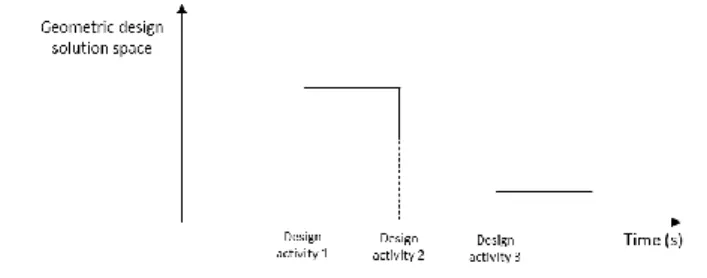
• The complete design process of a mechanical product is made of different activities performed by different stakeholders using different tools (Excel sheets, CAM, FEA…). So far, no PLM or CAD software solutions provide functions to visualise the impact of each decision of each activity on CAD model. As shown in Fig. 1, every design activity that takes decision should have an impact on the product solution space and therefore on the geometric solution space. Our research work will try to propose a visualization of this design space.
Fig. 1. Geometric design solution space
• The design tools on the market do not provide solution space visualisation to a defined design problem in order to find out the area of potential innovation and freedom space regarding design constraints. As written in [1], design rational must not exclude a solution from the design solution space if this solution is not explicitly un-admissible.
1.2. Objective
According to this context, we will propose a design environment that will allow visualising the emergence of CAD model and its maturity definition from knowledge synthesis by least commitment [2]. Through such a design methodology we will be able to see whether our CAD model is always fully justified or constrained by designers’ knowledge or not as well as the design maturity of each form feature. Such an environment will help the designer to point out the non-constrained elements and therefore the degree of freedom he has to innovate and/or optimise the geometry.
2. Literature review on knowledge synthesis and design maturity visualization
Our literature review will then be focused on the three major points of our research work which are:
• The ability to justify a geometric CAD model out of a complete knowledge synthesis during the design process.
• How to build up and display (i.e. visualization metaphor) design maturity on a CAD model.
2.1. From knowledge synthesis to product geometry definition in early design
Knowledge synthesis has been applied in early design for many purposes. When it comes to find out methodologies
linking knowledge synthesis to the product form features definition in early design, the literature review results are far more reduced. Some works using the Design For X (DFX) approach have tackled this link between product geometry and knowledge synthesis.
One example of such an approach is detailed in [3] [4], Design For Manufacturing methodology is applied throughout skin-skeleton modelling to early design. This approach is built on two geometrical models of the product, the usage model and the interface model, in order to help designers to visualize both functional and manufacturing constraints during early design process. Another similar example is described in [5], the Design For Materials research work aims here at visualising the typology and the geometry according to functional and material specifications and constraints in preliminary design.
Research works have also been lead not only focused on one specific view (DFX) but on the overall design process and its multi-domain constraints to explore and visualize the design space in early design steps. In the article [6] is presented a global concept to explore and analyze the solution space using an interoperability fitted loop that allows moving from knowledge database to simulation, optimization and CAD visualisation. One example of such an approach is presented in [7] throughout the so-called spring designer tool that allow to generate the solution space of CAD spring models to a spring design problem.
We find out similar knowledge synthesis approach in engineering grammars concept developed in [8]. We catch up here the design knowledge throughout computer-based grammar representation (string, set, shape or graph) and build up an automated design generator that allow to explore the design space for a defined application. In the example developed in [9], the design knowledge is represented by design rules. The engineering grammar methodology is then used to generate and visualize multiple geometries and configurations of gearboxes to a defined use case with its constraints.
2.2. Around design maturity visualisation of CAD model As mentioned in [10], maturity is defined as the association of knowledge and performance. The maturity value is the state of the information transmitted or displayed.
The most obvious way to visualize an additive value on a CAD model is using color-coded representation. According to the article [11], color-coded 3D representations allow the engineers to make a more extensive use of information during early design analysis. Papers give some applications of color-coded CAD model applied to environmental impact visualization [12]. Research work has been performed in color-coded CAD model applied to value-visualization in preliminary design. In the study [13] is presented a value representation approach. The targeted value is displayed to colors throughout a specific scale that evaluates the value level compared to the requirement target.
All this value driven design has been applied to specific values such as cost, weight, CO2 emissions… There is nevertheless no application to a more abstract and subjective
value such as design maturity. Indeed, it could make sense to benefit from the simple and easy to read color-coded CAD model to display an abstract maturity value that could sometimes be difficult to perceive in early design.
2.3. Literature review synthesis
To discuss the literature review, the concept of synthesis as presented, will be kept. Our focus will then be to “write” synthesis rules that could be used for CAD model generation. For our research work, we will organize and register our product knowledge synthesis and design rules into multiple perspectives (i.e. view) product model that will act as mediator (cf Fig. 2). This will allow us to model all stakeholders’ knowledge, constraints, design rules and optimization objectives into a unified product model. The finality will therefore be to generate a geometric CAD model out of all this knowledge synthesis.
As underlined in 2.2., displaying CAD model maturity with a color-coding scale appears to be relevant for our application. Instead of evaluating a defined and quantifiable value, we will use this color-coding CAD model to indicate the level of maturity or level of definition of the form features in order to underline the possible degree of freedom the engineer can have to be innovative.
3. Proposed knowledge synthesis approach for CAD emergence and visualization
Our proposal is a design environment that will allow justifying and visualising the emergence of the CAD geometric model from knowledge synthesis of all the stakeholders interacting in the design process. Indeed, as detailed in the introduction, the design process of a mechanical part is composed of different activities of different nature (manufacturing, design, assembling…). The knowledge of design stakeholders justifies the existence of geometric elements in the rational CAD model. The objective of such a design environment is to go to the 100% rational CAD model out of this knowledge displaying the maturity of each geometric element to help the designer to point out the fixed as well as innovative space to his design problem. The rational indeed comes from continuous digital chain which structures knowledge models and CAD.
3.1. Design environment definition
The design environment will be built up around four main functions shown in Fig. 2:
• Function 1: Modeling knowledge and constraints of all different stakeholders of the design process. That is the formalization of each stakeholder’s decision. Those models are based on specific meta-models that act as Domain Specific Languages (DSL) and specific software application. Many of those meta-models and specific software applications exist in design processes and industries the research work does not intend to invent new ones and keep them as input of the proposal. Since they are heterogeneous, the next function
(Function 2) goals at federating the instances of those meta-models.
• Function 2: Definition of the multiple-perspectives product model that will be our “knowledge synthesis mediator” providing the links among stakeholders’ knowledge and the link between stakeholders’ knowledge and CAD model of the product. In this approach, the unified model aims at reporting the synthesis of DSL knowledge a unique feature model (i.e. composed of feature views of the multiple-perspective product model). In the literature, we can find many meta-models that can act as mediator. Generally, those meta-models offer semantic independent concepts to formalize links between data (Core Product Model [14], FBS [15], MOKA model [16], KC model [17]). This paper does not discuss those meta-models in detail since they could all be relevant as mediator. Nevertheless, PPO offers the “multiple-perspective” concept which is relevant to formalize the origin (i.e. rational) of each design data and the form features ones. PPO is based on four concept that are detailed in [18]:
• BOM breakdown (component) that include multiple perspective characteristics.
• Interface that allow to link different components of different BOM.
• Relation that formalize how components are linked. • Attributes that characterize either components,
interfaces or relations.
• Function 3: Generation of the rational CAD model out of this multiple-perspectives product model by knowledge synthesis.
• Function 4: CAD model visualization providing a color-coded maturity display.
4 Anthony GEROMIN/ Procedia CIRP 00 (2018) 000–000
3.2. Case study: Drive shaft design
The case study, defined by our partner Asquini MGP, is a drive shaft design for helicopters (cf. Fig. 3).
Fig. 3. Drive shaft applied to helicopters
The main function of this drive shaft is to transmit torque; however, it must also support displacement of the input and output parts. Therefore, the particularity of this application is that we must design a shaft that will allow angular and axial displacement flexibility as well as torque transmission. The shaft should be rigid in some directions and allow flexibility in some others.
3.3. CAD model generation out of knowledge synthesis At Asquini MGP Company, the design process of such an application (drive shaft) is composed of the following activities:
• 1st activity: Requirement specifications acquisition • 2nd activity: Raw material selection
• 3rd activity: Assembling BOM selection
• 4th activity: Static and dynamic mechanical analysis • 5th activity: Flexible coupling assessment
• 6th activity: Fatigue analysis
The chronologic order of the different design activities is not discussed so far. It will be treated in the future works. This paper focuses on the knowledge synthesis toward form features modelling and visualisation (functions 2&3 on figure 2).
We will now detail two of the six activities (the 2nd and 3rd), illustrate and explain the relationship between knowledge and CAD model that will be supported by our PPO multiple-perspectives product model.
Since the drive shaft is a revolution part, we decided to present the results with a 2D CAD model in this paper. This represents the section of the shaft. Form features are however 3D features in our research work.
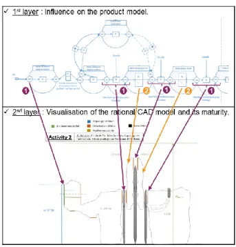
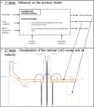
As generic template, for each design activity, directly linked to design stakeholders, we structure our design environment into two layers defined in Fig. 4 out of the four main functions of our design platform. The 2nd layer is definitively the added value of the work and presented in this paper.
Fig. 4. Development organization
Assembling BOM selection (3rd activity)
Layer 1: at this step, we cannot manufacture the shaft in one single part. The assumption of turning process has indeed been done. The stakeholder, therefore decide to divide our shaft into several parts that will be assembled afterward. Two of these parts (pointed with orange arrows in Figure 5) will provide the axial and angular flexibility. The other will be rigid coupling parts.
The assembling process chosen will be electron beam welding which integrates new constraints in our product model, like an electron welding flow (grey tubes) and symmetrical interfaces (pointed with purple arrows).
The meta-model used in this activity is based on energetic flow modelling [19].
Layer 2: we can clearly observe in Fig. 7 that this knowledge provided by the activity’s stakeholder generates geometric form features on the CAD model:
• Arrows 1: Element that will ensure an interface with motor interface according to the specification and ensuring symmetrical interfaces for soldering and assembling.
• Arrows 2: Element that will provide the angular flexibility to the shaft.
Static and dynamic mechanical analysis (4th activity)
Fig. 7. Presizing analysis
Layer 1: based on the engineer knowledge who knows that for torque transmission the optimized geometry is a tubular geometry, we sized the minimal dimensions of the tube. The aim of this analysis is to provide a minimum limit for diameter and thickness regarding torque and natural frequencies specifications. As the engineer is working with the idea to minimize the weight of the shaft, this minimal diameter and thickness will be applied to the surrounding elements.
Layer 2: We can observe on Fig. 7 the evolution of the CAD model integrating tubular geometry and diameter and thickness constrained and a minimum value.
• Final activity: Fatigue behavior sizing.
After all the design activities, we can clearly note the rational CAD model (Fig. 7, right picture) is relatively close to the initial CAD model the engineers had initially drawn on CAD tool (Fig. 7, left picture) but we have this time provided a maturity visualization and a knowledge justification to this model. We were able to justify with knowledge the existence of all geometric elements.
3.4. Maturity visualization on the final CAD model
At the end of the design process we are able to display the rational CAD (Fig. 7, left picture) coming from knowledge synthesis. Nevertheless, parameters and values of each form features are not 100% defined. A first work has been to identify several levels of form feature maturity:
• A form feature is identified from knowledge synthesis. Implicitly, parameters of this form features are identified. At this level, values are note ranged with min or Max limits.
• Parameters are ranged with max and min values coming from knowledge synthesis. At this level, parameters still have many admissible values.
• Parameters have one nominal value. At this stage sufficient knowledge has been defined and propagated to obtain one value for one parameter.
As mentioned in 3.1., we decided in this first approach to display those levels of maturity through the following color-coded scale:
• Green: The geometric element is completely fixed and defined (typology, orientation and position are defined and constrained by knowledge).
• Orange: The geometric element is completely defined but its position is not fixed, only constrained within a range (typology, orientation and position are defined and constrained by knowledge).
• Yellow: Only the topology and orientation of the geometric element are constrained.
Fig. 6. Fatigue behaviour sizing
Final activity Completly fixed. Topology defined. Non-constrained. Postion constained within a range.
Only typology and orientation are constrained.
6 Anthony GEROMIN/ Procedia CIRP 00 (2018) 000–000
• Blue: Only the topology of the geometric element is constrained.
• Black: The geometric element is not constrained, and its existence is not justified by knowledge.
4. Conclusions and future work
The objective of this research is to propose a design environment to build up, in preliminary design, the geometric CAD model out the knowledge synthesis of all the stakeholders that will take part to the design and manufacturing process. This design environment is going to be coordinated by a multiple-perspectives PPO model that will be the federative architecture that will provide the bridge among knowledge and between knowledge and CAD model definition. Our design environment will intend to provide a rational CAD model to the designer in order to help him to identify the scope for innovation as well as the unchangeable (i.e. constrained) elements.
The perspectives of our scientific work would be, on the one hand, to implement the synthesis rules that have been specified and to assess the influence of every design decision on the rational CAD model. On the other hand, the color-based visualisation of CAD model maturity is going to be assessed by users. One idea is to use questionnaires many often used for GUI ergonomic assessment. One idea could be to implement our tool as an add-on of an existing commercial CAD, like shown in [20], but the interoperability between our PPO model and commercial CAD would require complex modifications. As a consequence, we will create an algorithm that will assess the bridge between the PPO model and a open sources CAD software (i.e. FreeCAD). The main purpose is to provide design engineers software that will move directly from design rules specifications to CAD visualization throughout the mediator PPO model running in background.
Another perspective concerns the innovation capability of our industrial partner. So far, in our case study, to respect Asquini MGP capabilities and means, we have assumed and restricted some technical choices (fixed material catalogue, fixed manufacturing processes, predefined architectures catalogue of flexible couplings…). Now, we are able to master the solution design space by least commitments in order to assess the integration of new solutions. For example, the additive manufacturing could be an alternative to usual machining process.
Acknowledgements
Work presented in this paper was performed with the close partnership of the company Asquini MGP (Web: http://www.nexteam-group.com/).
References
[1] W. Es Soufi, L. Roucoules, E. Yahia, and S. Tichkiewitcht,
“Engineering design memory for design rationale and change management toward innovation,” p. 4, 2016.
[2] L. Roucoules and S. Tichkiewitch, “Knowledge synthesis by least
commitment for product design,” CIRP Annals - Manufacturing
Technology, vol. 64, pp. 141–144, 2015.
[3] E. Asadollahi-Yazdi, J. Gardan, and P. Lafon, “Integrated Design for
Additive Manufacturing Based on Skin-Skeleton Approach,” Procedia
CIRP, vol. 60, no. Supplement C, pp. 217–222, Jan. 2017.
[4] A. Skander, L. Roucoules, and J. S. K. Meyer, “Design and
manufacturing interface modelling for manufacturing processes selection and knowledge synthesis in design,” Int J Adv Manuf Technol, vol. 37, no. 5–6, pp. 443–454, May 2008.
[5] J.-B. Bluntzer, E. Ostrosi, and J. Niez, “Design for Materials: A New
Integrated Approach in Computer Aided Design,” Procedia CIRP, vol. 50, no. Supplement C, pp. 305–310, Jan. 2016.
[6] T. Østergård, R. L. Jensen, and S. E. Maagaard, “Building simulations
supporting decision making in early design – A review,” Renewable
and Sustainable Energy Reviews, vol. 61, no. Supplement C, pp. 187–
201, Aug. 2016.
[7] W. O. Schotborgh, H. Tragter, F. G. M. Kokkeler, and F. J. A. M. van
Houten, “A bottom-up appraoch for automated synthesis support in the engineering design process: Prototypes,” DS 36: Proceedings DESIGN
2006, the 9th International Design Conference, Dubrovnik, Croatia,
2006.
[8] A. Chakrabarti et al., “Computer-Based Design Synthesis Research: An
Overview,” J. Comput. Inf. Sci. Eng, vol. 11, no. 2, pp. 21003-21003– 10, Jun. 2011.
[9] K. Shea, Y.-S. Lin, A. Johnson, J. Coultate, and J. Pears, “A method
and software tool for automated gearbox synthesis,” ASME, p. 11, 2009.
[10] M. B. Chrissis, M. Konrad, and S. Shrum, CMMI: Guidelines for
Process Integration and Product Improvement, 2 edition. Upper Saddle
River, NJ: Addison-Wesley, 2006.
[11] A. Bertoni, “Analyzing Product-Service Systems conceptual design: The effect of color-coded 3D representation,” Design Studies, vol. 34, no. 6, pp. 763–793, Nov. 2013.
[12] H. Ostad-Ahmad-Ghorabi, D. Collado-Ruiz, and W. Wimmer, “Towards Integrating LCA into CAD,” DS 58-7: Proceedings of ICED
09, the 17th International Conference on Engineering Design, Vol. 7, Design for X / Design to X, Palo Alto, CA, USA, 24.-27.08.2009, 2009.
[13] M. Bertoni, A. Bertoni, and O. Isaksson, “Experinces with value visualisation in preliminary design : result from an aero-engine component study,” 2012.
[14] R. Sudarsan, S. J. Fenves, R. D. Sriram, and F. Wang, “A product information modeling framework for product lifecycle management,”
Computer-Aided Design, vol. 37, no. 13, pp. 1399–1411, Nov. 2005.
[15] J. S. Gero, “Design Prototypes: A Knowledge Representation Schema for Design,” AI Magazine, vol. 11, no. 4, p. 26, Dec. 1990.
[16] W. Skarka, “Application of MOKA methodology in generative model creation using CATIA,” Engineering Applications of Artificial
Intelligence, vol. 20, no. 5, pp. 677–690, Aug. 2007.
[17] J. Badin, D. Monticolo, D. Chamoret, and S. Gomes, “Using the knowledge configuration model to manage knowledge in configuration for upstream phases of the design process,” Int J Interact Des Manuf, vol. 5, no. 3, p. 171, Aug. 2011.
[18] F. Noël and L. Roucoules, “The PPO design model with respect to digital enterprise technologies among product life cycle,” International
Journal of Computer Integrated Manufacturing, vol. 21, no. 2, pp. 139–
145, Mar. 2008.
[19] J.-S. K. Meyer, L. Roucoules, A. D. Grave, and J. Chaput, “Case Study of a MEMS Switch Supported by a FBS and DFM Framework,” in The
Future of Product Development, Springer, Berlin, Heidelberg, 2007, pp.
377–386.
[20] J. Pandremenos and G. Chryssolouris, “A CAD based tool for the support of modular design,” 21st CIRP Design Conference, Deajon,
South Korea, pp. 154–158, 2011.