UNIVERSITY OF QUEBEC AT CHICOUTIMI
A DISSERTATION PRESENTED TO THE UNIVERSITY OF
QUEBEC AT CHICOUTIMI IN PARTIAL FULFILLMENT
OF THE REQUIREMENT FOR THE DOCTOR
OF PHILOSOPHY IN ENGINEERING
BY
LANFENG JIN
DEVELOPMENT OF AL–SI CAST ALLOYS FOR
ELEVATED-TEMPERATURE APPLICATIONS
THESE PRÉSENTE À
L’UNIVERSITÉ DE QUÉBEC À CHICOUTIMI
COMME EXIGENCE PARTIELLE
DU DOCTORAT EN INGÉNIERIE
PAR
LANFENG JIN
DÉVELOPPEMENT D’ALLIAGES FONDERIE D’AL-SI
POUR LES APPLICATIONS ÀTEMPÉRATURE ÉLEVÉE
Abstract
Aluminum Silicon (Al–Si) alloys are considered as the most important alloys among aluminum cast alloys and have been widely used in many industries, especially the aerospace and automotive industries. In order to further reduce the vehicle weight and therefore reduce the greenhouse gas emission, the growing demand for lighter and stronger Al–Si alloys for elevated-temperature applications has been one of many important scientific focuses in advances of conventional Al alloys. The general objective of the present study is to develop new Al–Si cast alloys that can be fabricated by conventional metallurgy route, through appropriate heat treatment to enhance their elevated-temperature (250 °C-350 °C) properties. This often necessitates the introduction of new alloy elements and subsequent optimization of alloy compositions. Hence, the influence of Mo and Mn elements on the microstructure and mechanical properties at both ambient and elevated temperatures in Al-6 wt.%Si-3.5 wt.% Cu 319 and Al-13 wt.% Si piston alloys were investigated in the present work.
For microstructure study, transmission electron microscope, scanning electron microscope and optical microscope equipped with an image analysis system were used. The mechanical properties at ambient temperature were evaluated by Vickers microhardness measurements and compression yield strength tests. The elevated-temperature mechanical properties and creep properties were assessed by compression yield strength tests and creep tests at 300oC. The results obtained were
divided into following three parts.
In the first part, the precipitation and preferential selection of Fe-rich intermetallics in Al–Si–Cu 319 cast alloys with two Fe contents (0.3 and 0.7 wt.%) and various Mo contents (0-0.4 wt.%) were investigated. The results showed that two types of platelet β-Fe (defined as eutectic β-Fe and pre-eutectic β-Fe) and α-Fe can
pre-eutectic β-Fe amount decreases with increasing Mo addition, leaving the eutectic β-Fe almost unchanged. On the other hand, both pre-eutectic β-Fe and eutectic β-Fe can be fully suppressed with a combined addition of Mn (0.24 wt.%) and Mo (0.4 wt.%). Compared with Mn, Mo exhibits a stronger effect on the promotion of α-Fe. The combined addition of Mn and Mo can achieve better modifications of both pre-eutectic and eutectic β-Fe in 319 alloys with high Fe content.
In the second part, the effects of Mo and Mn additions on the evolution of dispersoids during various heat treatment conditions were investigated in 319 cast alloys. Furthermore, their effects on yield strength and creep resistance at elevated temperature (300 oC) were studied. The results showed that the additions of Mo or/and Mn can greatly improve the precipitation the dispersoids during heat treatment, while 500 oC /8h was found to be the optimal heat treatment condition characterized with the largest quantity and the smallest size of α-dispersoids. This was also confirmed by the improved yield strength at both room temperature and 300 oC. Meanwhile, the creep resistance at 300 oC was greatly improved due to the Mn and Mo additions, with doubled threshold stress (from 10.6 to 22.8 MPa) and 50 times lower minimum creep rate (from 5.5E-7 s-1 to 1.1E-8 s-1). During the long-time exposure at 300 oC service temperature up to 1000 h, the decrease rate of
elevated-temperature properties is much slower due to the presence of dispersoids from the Mn or/and Mo additions, which is 10% decrease in yield strength and 5% increase in the maximum creep strain in alloys with combined additions of Mn and Mo compared with 47% and 30% in base alloy free of Mn and Mo, respectively,
showing the superior thermal stability of Al–Si–Cu 319 alloys with Mn and Mo additions and then widening their applications at elevated temperature.
In the third part, the precipitation of dispersoids by Mo additions in a Mn-containing Al-13 wt.% Si piston alloy was studied by characterization of the dispersoid zone and dispersoid free zone during heat treatment using optical, scanning electron and transmission electron microscopes. The influence of the Mo addition and its dispersoids on the yield strength and creep resistance at 300 oC was investigated. The evolution of microstructure, yield strength and creep resistance during prolonged thermal exposure at 300 oC up to 1000 h were also studied. Results showed that compared with the individual Mn-containing base alloy, Mo can further enhance the precipitation of α-dispersoids by expanding dispersoid zone and restricting the dispersoid free zone after the precipitation treatment at 520 oC for 12 h, resulting in a remarkable improvement of yield strength at both room temperature and 300 oC as well as the creep resistance at 300 oC. The beneficial effect of the Mo addition on the
improved yield strength and creep resistance is especially prominent during the long-term thermal exposure at 300 oC due to the presence of thermally stable dispersoids and the retardation of the fragmentation and spheroidization of Si particles.
réduire d’avantage le poids du véhicule, ce qui a la réduction des émissions de gaz à effet de serre. La demande croissante d'alliages Al-Si plus légers et plus résistants pour les applications à température élevée a été l'un des nombreux objectifs scientifiques importants dans les progrès des alliages d'aluminium conventionnels. L’objectif général de la présente étude est de développer de nouveaux alliages de fonderie Al-Si pouvant être fabriqués par la métallurgie conventionnelle tout en appliquant un traitement thermique approprié, afin d’améliorer leurs propriétés de température élevée (250 °C-350 °C). Cela nécessite souvent l'introduction de nouveaux éléments d'alliage et l'optimisation ultérieure des compositions d'alliage. Ainsi, l’influence des éléments Mo et Mn sur la microstructure et les propriétés mécaniques à la fois à température ambiante et à température élevée dans les alliages de piston à 319 et Al-13% Si ont été étudiés.
Pour l'étude de la microstructure, un microscope électronique à transmission, un microscope électronique à balayage et un microscope optique équipés d'un système d'analyse d'image ont été utilisés. Les propriétés mécaniques à la température ambiante ont été évaluées par des mesures de microdureté Vickers et des tests de résistance à la compression. Les propriétés mécaniques et les propriétés de fluage à température élevée ont été évaluées par des tests de résistance à la compression et des tests de fluage à température élevée. Les résultats obtenus ont été divisés en trois parties.
Dans la première partie, la précipitation et la sélection préférentielle des composés intermétalliques riches en Fe dans les alliages Al–Si–Cu 319 avec deux
teneurs en Fe (0,3 et 0,7% en poids) et diverses teneurs en Mo (0-0,4% en poids) ont été étudiées. Les résultats ont montré que deux types de plaquettes β-Fe (définis comme eutectiques β-Fe et pré-eutectiques β-Fe) et α-Fe peuvent précipiter en fonction des compositions d'alliage, telles que les teneurs en Fe et Mo. En général, l'ajout de Mo favorise la formation de α-Fe au lieu de β-Fe. Cependant, son effet sur la compétition de phase entre β-Fe et α-Fe est fortement lié à la teneur en Fe. Dans les alliages à faible teneur en Fe (0,3%), une addition de 0,37% de Mo peut favoriser la précipitation complète de l'α-Fe et supprimer la formation de β-Fe eutectique. Pourtant, dans les alliages à teneur élevée en Fe (0,7%), seule la quantité de β-Fe pré-eutectique diminue avec l’augmentation de l’ajout de Mo, laissant le β-Fe eutectique presque inchangé. La β-Fe pré-eutectique et la β-Fe eutectique peuvent être complètement supprimées avec une addition combinée de Mn (0,24%) et de Mo (0,4%). Comparé au Mn, le Mo exerce un effet plus marqué sur la précipitation de l'α-Fe. L'addition combinée de Mn et de Mo peut permettre d’avoir de meilleures modifications des β-Fe pré-eutectiques et eutectiques dans les alliages 319 à haute teneur en Fe.
Dans la deuxième partie, les effets d'alliages d'additions de Mo et de Mn sur l'évolution des dispersoïdes au cours de diverses conditions de traitement thermique ont été étudiés dans 319 alliages moulés. De plus, leurs effets sur la YS (limite d'élasticité) et la résistance au fluage à température élevée (300 °C) ont été étudiés. Les résultats ont montré que Mo et la combinaison de Mo et de Mn peuvent grandement améliorer la précipitation des dispersoïdes lors du traitement thermique. Le traitement thermique 500 oC/8h était la condition optimale caractérisée par la plus grande quantité et la plus petite taille de α-dispersoïdes. Cela était confirmée par la limite d'élasticité améliorée à la température ambiante et également pour la température de 300 °C. En parallèle, la résistance au fluage à 300 °C a été grandement améliorée grâce aux ajouts de Mn et de Mo, avec une contrainte de seuil doublée (de 10,6 à 22,8 MPa) et un taux de fluage minimum 50 fois plus bas (de 5,5 E-7 s-1 à
alliage de base dépourvu de Mn et de Mo respectivement. Cela montrait une stabilité thermique supérieure des alliages Al–Si–Cu 319 avec des additions de Mn et de Mo, puis en élargissant leurs applications à température élevée.
Dans la troisième partie, la précipitation de dispersoïdes par addition de Mo dans un alliage piston à 13% de Si contenant Mn a été étudiée par caractérisation de la zone dispersoïde et de la zone exempte de dispersoïde lors du traitement thermique à l'aide de microscopes optiques, à balayage et à transmission. L'influence de l'addition de Mo et de ses dispersoïdes sur la limite d'élasticité et la résistance au fluage à 300 °C a été étudiée. L'évolution de la microstructure, de la limite d'élasticité et de la résistance au fluage au cours d'une exposition thermique prolongée de 300 °C à 1000 h ont également été étudiés. Les résultats ont montré que, comparé à l'alliage basique ne contenant que du Mn, le Mo peut encore améliorer la précipitation des α-dispersoïdes en agrandissant la zone dispersoïde et en limitant la zone exempte de dispersoïde après le traitement par précipitation à 520 oC pendant 12 h, entraînant une amélioration remarquable du rendement de la résistance à la température ambiante et à 300 °C ainsi que la résistance au fluage à 300 °C. L'effet bénéfique de l'addition de Mo sur l'amélioration de la limite d'élasticité et de la résistance au fluage est particulièrement important pendant l'exposition thermique à long terme à 300 °C, en raison de la présence de dispersoïdes thermiquement stables et du retard de la fragmentation et de la sphéroïdisation des particules de Si.
Acknowledgements
First, I would like to express my sincere gratitude to my supervisor Prof. X.-Grant Chen for offering me the opportunity to conduct the PhD research, for
his continuous support, his patience, motivation, immense knowledge, stimulating
ideas and enlightening discussions. I am also thankful to my co-supervisor Prof. Kun Liu for his encouragement, whole-hearted support and his valuable
suggestions during the research. This dissertation would not be possible without his assistance. Special thanks to Prof. Zhan Zhang for helping me conducting SEM and TEM observation. Besides, I would also like to thank Prof. Dilip Sarkar for the course studies.
Secondly, I would also like to thank all the staff of Applied Science Department of University of Quebec at Chicoutimi for their help and support. Special thanks go to Dany Racine for his technical assistance in DSC, image analysis and mechanical tests. I would also like to thank Samuel Dessureault, Dave Girard, Pier-Luc Privé, Émélie Brideau for all the availability in the laboratory. I am also grateful to Dr. Jian Qin, Dr. Lei Pan, Dr. Zhen Li, Dr. Emad Elgallad, Belkacem Amara, Xiaoming Qian, Zhixing Chen for the fruitful discussions. Many thanks to all my colleagues and friends in the department for their kind support, help, suggestions, and making my life much more delightful in Chicoutimi.
In addition, I would like to thank my beloved mother and brothers for the unconditional love and support throughout my PhD research.
Finally, this dissertation is dedicated to my late father who had been the whole world to me, a role model in my entire life, his legacy will be forever remembered and cherished.
Lanfeng Jin, Kun Liu, X.-Grant Chen, Evolution of dispersoids and their effect on elevated-temperature properties and creep resistance in Al–Si–Cu 319 cast alloys with Mo and Mn additions. Ready to submit in 2019.
Lanfeng Jin, Kun Liu, X.-Grant Chen, Improved elevated-temperature properties in Al–13%Si piston alloy by Mo addition. To be submitted in 2019.
Posters:
Lanfeng Jin, Kun Liu, X.-Grant Chen, Effect of Mo on the microstructure and microhardness of 319 foundry alloy. REGAL Students’ Day, Chicoutimi, Canada, November. 2015 (Regal Prize).
Lanfeng Jin, Kun Liu, X.-Grant Chen, Formation of β-Al5FeSi with various Fe,
Mo addition in Al–Si–Cu–Mg foundry alloy. REGAL Students’ Day, Quebec, Canada, October. 2016.
Lanfeng Jin, Kun Liu, X.-Grant Chen, Enhanced properties via Mo addition in Al–Si–Cu–Mg cast alloy. 2017 REGAL Students’ Day, Montreal, Canada, September. 2017.
Lanfeng Jin, Kun Liu, X.-Grant Chen, Formation of dispersoids and their effect on creep property of Al–Si–Cu–Mg foundry alloy with additions of Mn and Mo. 2018 REGAL Students’ Day, Montreal, Canada, June. 2018.
Table of Contents
Abstract ... I Résumé ... IV Acknowledgements ... VII Publications ... VIII Table of Contents ... IX List of Tables ... XIII List of figures ... XIVChapter 1 Introduction ... 1
1.1 Background ... 1
1.2 Objectives ... 2
References ... 3
Chapter 2 Literature Review ... 5
2.1 Introduction of Al-Si alloys ... 5
2.2 Microstructure of Al-Si cast alloys ... 6
2.2.1 Main intermetallics in Al-Si alloys ... 7
2.2.2 Fe-rich intermetallics ... 11
2.3 Strengthening mechanisms at elevated temperature ... 14
2.3.1 Solid solution strengthening ... 14
2.3.2 Precipitation strengthening ... 15
2.3.3 Dispersoid strengthening ... 26
2.4 Creep behaviour and its mechanism ... 33
2.4.1 Creep stages ... 33
References ... 48
Chapter 3 Experimental ... 60
3.1 Alloy design and sample preparation ... 60
3.2 Heat treatment design ... 62
3.3 Property measurements ... 64
3.3.1 Microhardness ... 64
3.3.2 Yield Strength ... 64
3.3.3 Creep resistance ... 64
3.4 Microstructure characterization ... 65
3.4.1 Optical microscopy (OM) ... 65
3.4.2 Scanning electron microscopy (SEM) ... 65
3.4.3 Electron backscatter diffraction (EBSD) ... 65
3.4.4 Transmission electron microscopy (TEM) ... 66
References ... 67
Chapter 4 Evolution of Fe-rich intermetallics in Al–Si–Cu 319 cast alloy with various Fe, Mo, and Mn contents ... 68
4.1 Introduction... 68
4.2 Materials and Methods... 70
4.3.1 Precipitation of Fe-rich Intermetallics in experimental alloys ... 72
4.3.2 Evolution of Fe-rich intermetallics with Mo and Mn additions ... 81
4.4 Conclusions ... 90
References ... 92
Chapter 5 Evolution of dispersoids and their effect on elevated-temperature mechanical properties and creep resistance in Al–Si–Cu 319 cast alloys with Mo and Mn additions ... 96
5.1 Introduction... 96
5.2 Materials and Methods... 98
5.3 Results and discussion ... 100
5.3.1 As-cast microstructure and properties ... 100
5.3.2 Evolution of Dispersoids during heat treatment ... 101
5.3.3 Role of dispersoids on YS at RT and elevated temperature ... 107
5.3.4 Evolution of creep resistance with Mn or/and Mo additions ... 111
5.3.5 Long-term thermal stability of elevated-temperature properties ... 116
5.4 Conclusions ... 120
References ... 122
Chapter 6 Improved elevated-temperature properties in Al-13%Si piston alloys by Mo addition ... 126
6.1 Introduction... 126
6.2 Materials and Methods... 128
6.3 Results and discussion ... 130
6.3.1 As-cast microstructure of experimental alloys ... 130
6.3.2 Dispersoid evolution during heat treatment at 520 oC ... 133
List of Tables
Table 2.1 List of reactions during solidification of A319 Al alloy containing 0.08 wt.% Mg [21].
... 10
Table 2.2 Stress exponent and activation energy values for creep mechanisms [105]. ... 37
Table 3.1 Chemical compositions of the designed alloys ... 61
Table 3.2 Chemical compositions of experimental alloys ... 62
Table 3.3 Solution treatment conditions ... 63
Table 3.4 Thermal exposure conditions ... 63
Table 4.1 Chemical composition of the experimental alloys ... 72
Table 4.2 SEM-EDS results of the Fe-rich intermetallics shown in Fig. 4.1 ... 75
Table 4.3 Formation of Fe-rich intermetallics in experimental alloys ... 80
Table 5.1 Chemical compositions of the experimental alloys (wt.%). ... 99
Table 5.2 Creep properties of experimental alloys ... 113
Table 5.3 Summary of creep properties of experimental alloys ... 115
Table 6.1 Chemical composition of experimental alloys (wt.%) ... 129
Table 6.2 Area fraction of blocky Al-Mo primary phases ... 131
Table 6.3 Aspect ratio and average length of Si particles in experimental alloys ... 133
dendrite, (2) eutectic Si, (3)Al8Mg3Si6Fe, (4) Mg2Si, (5) Al2Cu, (6)Al5Mg8Cu2Si6 [19]. 8
Fig. 2.4 Temperature-time cooling curve and its first derivative obtained from A319.2 alloy+
0.6 wt. % Mg [21]... 9 Fig.2.5 Microstructures of the two different types of Fe intermetallic phases in the Type 319
aluminum alloy: (a) Chinese script α-phase and (b) needle β-Al5FeSi phase [36]. .... 12
Fig. 2.6 Schematic models of solid solutions: substitutional solid solution and interstitial solid solution [52]. ... 15 Fig. 2.7 Diagram showing the three steps for precipitation hardening [55]. ... 16 Fig. 2.8 Dislocations passing a precipitate by a) shearing and b) looping [57]. ... 17 Fig. 2.9 Dislocation meets undeformable second phase particles: dislocation release at higher
stresses may occur by Orowan looping or by cross-slip [58]. ... 18 Fig. 2.10 Typical β''precipitates and its corresponding SADP [67]. ... 22 Fig. 2.11 Typical β'precipitates and its corresponding SADP [67]. ... 22 Fig. 2.12 (a) TEM image of dispersoid nucleated on the surface of u-phase (b) a model of the precipitation of the dispersoids [71]. ... 23 Fig. 2.13 Unit cells of α–Al matrix and θ'', θ' and θ intermetallic phases [74]. ... 24 Fig. 2.14 (a) Bright-field transmission electron microscope micrograph depicting GPII in the
<100>Al zone obtained after aging at 438 K for 8 h; (b) the θ' precipitates in the<
100>Al zone observed after aging at 463 K for 8 h [75]. ... 25
Fig. 2.15 a) Bright field electron micrograph of 2219 after 4.7 d aging at 130oC. (b)
Corresponding selected area diffraction pattern [78]. ... 26 Fig. 2.16 (a) Bright field electron micrograph of θ', (b) Corresponding selected area diffraction
pattern [78]. ... 26 Fig. 2.17 Type of morphology of dispersoids: (a) SEM and (b) TEM image and SADP along
[211]Al (c) as well as the TEM-EDS results of dispersoids (d) in the sample treated at 375 °C for 48 h [82]. ... 29 Fig. 2.18 Diffraction patterns of α-dispersoids in 3003 alloy after heating to 500 °C [83]. .. 30 Fig. 2.19 Al–Mo phase diagram [91]. ... 31 Fig 2.20 (a) Bright field TEM micrograph showing the Al(Mo,Fe)Si dispersoids in the
interdendrite regions of the MG3R3M alloy formed after 10 h of solution treatment at 540 °C. (b) EDS spectrum of the Al(Mo,Fe)Si dispersoids [51]. ... 32 Fig. 2.21 EDS elemental line scanning across a dendrite cell showing the concentration
gradients of Mo and Mn (microsegregation) in the as-cast
Al–7Si–0.5Cu–0.3Mg–0.1Fe–0.3Mo–1.5Mn alloy [93]. ... 32 Fig. 2.22 Typical creep curve showing the three steps of creep (The dotted line shown in the
figure is for the compression creep curves) [70]. ... 34 Fig. 2.23 Ashby deformation map of silver. A – Dislocation glide creep, B –Dislocation creep, C
– Coble creep, D – Nabarro-Herring creep, E – Elastic deformation [106]. ... 36 Fig. 2.24 The steady-state temperature distribution within a high-performance piston obtained
by FE simulation [108]. ... 39 Fig. 2.25 Hardness-time-temperature (HTT) curves of the EN AW-4032 alloy, after forging and
T6 heat treatment [109, 110]. ... 40 Fig. 2.26 The Al–rich end of the Al-Cu phase diagram showing the metastable GP zone, θ" and
θ' solvus temperature [111]. ... 43 Fig. 2.27 Transmission electron micrographs of Al–Cu–Mg–Ag alloy, showing changes in
microstructure with ageing at 250 oC. (a) 5 h at 250 oC; θ' and θ phase. (b) 30 h at 250
oC; coarser θ' and θ particles. (c) 600 h at 250 oC; very coarse Ω precipitates, large θ'
and θ particles [113]. ... 43 Fig. 2.28 Transmission electron micrograph from alloy after 2400 h at 250oC. The electron
Alloy Mn1, (d) Alloy LM2, and (e) Alloy Mn3. ... 74 Fig. 4.2 TA curves of (a) Alloy L0 and (b) Alloy H0 as well as microstructure after interrupted water quench at: (c) 570oC and (e) 540 oC of Alloy L0; (d) 570 oC and (f) 540 oC
of Alloy H0 ... 77 Fig. 4.3 Chinese Script Fe-rich intermetallic in Alloy Mn3 (a) and its EBSD pattern (b) as well
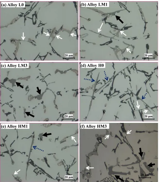
as the simulation results (c) ... 79 Fig. 4.4 TA curves of alloys: (a) LM3 and (b) HM3 and microstructure after interrupted water quench at 580 oC of (c) LM3 and (d) HM3 alloys (black arrows indicate α-Fe) ... 81 Fig. 4.5 Optical micrographs showing effect of Mo on microstructure for low-Fe (0.3%) alloys:
(a) L0, (b) LM1, and (c) LM3; for high-Fe (0.7%) alloys: (d) H0, (e) HM1, and (f) HM3 (white, blue dotted and black arrows indicate E-β-Fe, P-β-Fe, and α-Fe, respectively) ... 83 Fig. 4.6 Area fractions of α-Fe, P-β-Fe, and E-β-Fe for different Mo additions in (a) Low Fe
alloy, (b) High Fe alloy. ... 85 Fig. 4.7 DSC heating curves of (a) low-Fe alloys, (b) high-Fe alloys and (c) enlarged zone 5 in
(a) while (d) enlarged zone 4 in (b) ... 86 Fig. 4.8 Optical images of alloys: (a) Mn1, (b) Mn2, (c) Mn3, and (d) Mn4 (white, black, and
thick black arrows indicate E-β-Fe, P-β-Fe, and α-Fe, respectively) ... 88 Fig. 4.9 Area fractions of α-Fe, P-β-Fe, and E-β-Fe in experimental alloys ... 89 Fig. 4.10 Correlation between Mo and Mn contents with area fractions of (a) P-β-Fe and (b)
α-Fe in alloys with high Fe contents (0.7%) ... 90 Fig. 5.1 Typical as-cast microstructure of experimental alloys (a) Alloy A, (b) Alloy D, (c)
Microhardness and EC of as-cast experimental alloys. ... 101 Fig. 5.2 Distribution of dispersoid zone and DFZ in experimental alloys heat treated at 400oC and 450oC. ... 103
Fig. 5.3 Distribution of dispersoid in Alloys B, C and D heat treated at 500oC. ... 104 Fig. 5.4 Area fraction of the dispersoid zone in experimental alloys after 500 oC treatment 105 Fig. 5.5 TEM bright filed images showing dispersoids evolution in experimental alloys and
their corresponding TEM-EDS analysis results ... 106 Fig. 5.6 Evolution of YS at RT (alloys solution treated then tested at RT) ... 108 Fig. 5.7 Evolution of Yield Strength for experimental alloys tested at RT after T6(red line),
tested at ET after T6+thermal exposure at 300oC/100h( blue line) ... 109
Fig. 5.8 TEM micrographs of Alloy A (a) T6, (b) T6+300oC/100 and Alloy D (c) T6, (d) T6+300oC/100h, red arrows indicate the Cu precipitates; blue arrows
indicate the α-dispersoids... 111 Fig. 5.9 Typical creep curve under a constant load of 30 MPa (alloys treated at 500 C for 8h,
then 155 C/5h aged followed by 300 oC/100h soaking.) ... 113 Fig. 5.10 Logarithmic plots of the minimum creep rate εm vs. applied stress σ for alloys tested at
300 C ... 114 Fig. 5.11 Arrhenius plots-Logarithmic plots of the steady stage minimum creep rate Lnε vs. 1/T
under an applied stress of 30 MPa. ... 116 Fig. 5.12 Evolution of YS during a long-term thermal holding at 300 C in experimental alloys. ... 117 Fig. 5.13 Comparison of (a) Total strain and (b) minimum creep rate for four experimental
alloys after long-time thermal holding at 300 C for 100h and 1000h. ... 118 Fig. 5.14 TEM bright field images showing α-dispersoids and Cu precipitates in Alloy A and D
after T6+thermal exposure at 300 oC/1000h (red arrows indicate the Cu precipitates;
blue arrows indicate the α-dispersoids) ... 119 Fig. 6.1 Microstructure of experimental alloys, (a) B0 and (b) B3. ... 131 Fig. 6.2 Optical micrographs of (a) B0, (b) B1, (c) B2 and (d)B3 alloys showing the effects of
Fig. 6.6 Evolution of Yield Strength for Alloy B0 and B2 at 25 oC and 300 oC ... 137 Fig. 6.7 Evolution of Yield strength for Alloy B0 and B2 during prolonged thermal exposure at
300 oC ... 138
Fig. 6.8 Evolution of creep resistance for Alloys B0 and B2tested at 300 oC under the constant
load of 35 MPa ... 139 Fig. 6.9 Evolution of Creep resistance for Alloy B0 and B2 at 300 oC. ... 140
Fig.6.10 TEM bright field images showing the (a) β''-Mg2Si precipitates and (b) their
corresponding SADP; (c) α-dispersoids and precipitates after 300o
C/1000h (yellow dotted arrows indicate the α-dispersoids, black arrows indicate the coarsened β precipitates) and (d) their corresponding SADP confirming equilibrium β-Mg2Si
precipitates. ... 142 Fig. 6.11 Evolution of Si particles during thermal exposure in Alloy B0 and B2 at various heat
treatment conditions. ... 143 Fig. 6.12 SEM micrographs showing the morphology change of Si particles in deep etching
Chapter 1 Introduction
1.1 Background
Al–Si alloys have attracted increasing attentions for the combination of excellent castability and modest strength [1]. Besides, their good machinability makes them perfect candidates in various areas of manufacturing and technology fields especially in auto industry [1]. However, the growing demand for higher fuel efficiency and light weight structure components at elevated temperatures remains a big challenge for weight-sensitive automobile industries [2]. Some traditional Al-Si cast alloys can meet the requirement of room temperature applications by precipitation of various Cu and Mg containing precipitates [3]. Yet, due to the rapid coarsening of these nano-scale precipitates at elevated temperature (overageing effect), their applications at elevated temperature are greatly restricted [4]. In recent years, the dispersoid strengthening in AA3xxx alloys has been discovered and investigated [5-7], and the mechanical properties at both room and elevated temperature could be improved significantly [8, 9]. Moreover, dispersoids as the main strengthening phase have been proved to be thermally stable at elevated temperature [8]. Hence, introduction of dispersoids into Al-Si cast alloy to obtain the improved strength at both room and elevated temperature is highly feasible.
Mn can form thermally stable nano-scale α-Al(Fe, Mn)Si dispersoids and has been reported to be able to improve mechanical properties at elevated temperature [10]. More recently, Mo is also investigated to be able to precipitate α-Al(Fe, Mo)Si dispersoids and improved yield strength was achieved at both room and elevated temperature [10]. Besides, combined addition of Mo and Mn can also form large volume of thermally stable dispersoids, resulting in significant enhancement in strength [10-12].
will be systematically investigated.
1.2 Objectives
The main objective of this project is to explore the application of Al-Si cast alloy for elevated temperature applications (250-300 oC). To achieve the objective, the research will be performed in several parts listed as follows:
1. Study the solidification of Al-Si cast alloy and formation of different types of Fe-rich intermetallics. Investigate the effect of Mo or and Mn additions on the evolution of Fe-rich intermetallics.
2. Determine the optimal heat treatment parameters for maximizing dispersoid formation via studying a series of different heat treatment conditions.
3. Study the effect of α-dispersoids on the yield strength of Al–Si cast alloys at both ambient and elevated temperature.
4. Investigate the effect of dispersoids on creep resistance at 300 oC in Al-Si cast alloys.
5. Analyze the effect of dispersoids on thermal stability of Al-Si cast alloys by thermal exposure at 300 oC.
References
[1] F.C.R. Hernandez, J.M.H. Ramírez, R. Mackay, Al-Si Alloys: Automotive, Aeronautical, and Aerospace Applications, Springer International Publishing2017. [2] M. Javidani, D. Larouche, Application of cast Al-Si alloys in internal combustion engine components, International Materials Reviews 59(3) (2014) 132-158.
[3] J.W. Martin, Precipitation hardening, Butterworth-Heinemann1998.
[4] C. Booth-Morrison, D.C. Dunand, D.N. Seidman, Coarsening resistance at 400 °C of precipitation-strengthened Al–Zr–Sc–Er alloys, Acta Materialia 59(18) (2011) 7029-7042.
[5] Y.J. Li, L. Arnberg, Quantitative study on the precipitation behavior of dispersoids in DC-cast AA3003 alloy during heating and homogenization, Acta Materialia 51(12) (2003) 3415-3428.
[6] L. Lodgaard, N. Ryum, Precipitation of dispersoids containing Mn and/or Cr in Al–Mg–Si alloys, Materials Science and Engineering: A 283(1–2) (2000) 144-152. [7] Y.J. Li, A.M.F. Muggerud, A. Olsen, T. Furu, Precipitation of partially coherent α-Al(Mn,Fe)Si dispersoids and their strengthening effect in AA 3003 alloy, Acta Materialia 60(3) (2012) 1004-1014.
[8] K. Liu, X.G. Chen, Development of Al-Mn-Mg 3004 alloy for applications at elevated temperature via dispersoid strengthening, Materials & Design 84 (2015) 340-350.
[9] A.M.F. Muggerud, E.A. Mørtsell, Y. Li, R. Holmestad, Dispersoid strengthening in AA3xxx alloys with varying Mn and Si content during annealing at low temperatures, Materials Science and Engineering: A 567 (2013) 21-28.
[10] A.R. Farkoosh, X.G. Chen, M. Pekguleryuz, Dispersoid strengthening of a high temperature Al-Si-Cu-Mg alloy via Mo addition, Materials Science and Engineering: A 620 (2015) 181-189.
Chapter 2 Literature Review
2.1 Introduction of Al-Si alloys
In 21th Century the auto industry has paid increasing attention to the
elevated-temperature applications of materials [1]. The relatively high service temperature requires engineering materials to possess high strength, high modulus of elasticity, abrasion resistance, corrosion resistance etc. Ideally, the material should also have a low density to increase fuel efficiency. Besides, low thermal expansion, and high thermal conductivity are also desirable for elevated-temperature application materials. In addition, good machinability and castability are also important factors in selecting the proper material, as the harder it is to machine the product, the higher the costs of manufacturing. Last but not the least, the alloys must possess good vibration damping to absorb the shuddering of the moving parts.
Among numerous engineering materials to meet above mentioned requirements, Al-Si alloys have been widely used in the automotive industry as a suitable alternative of cast iron in fabrication of engine components. Commonly used Al-Si cast alloys contain Si between 5-25 wt.% [1]. The Al-Si alloys generally have good castability due to its relatively high Si concentration, which increases alloy fluidity, making these alloys ideal for casting components with complex geometries without considerably raising the cost. Besides their high strength to weight ratio, their excellent thermal conductivity also allows the combustion heat to be extracted more rapidly and efficiently [1, 2]. In addition, by alloying other elements, such as Cu and Mg, Al-Si alloys can be further strengthened by forming a variety of precipitates.
Al-Si alloys are usually applied artificial ageing after solution treatment to obtain the optimum properties, and they are generally gravity casted to fabricate engine blocks. Fig. 2.1 shows the common applications of Al-Si alloys as engine block and
Fig. 2.1 (a) Cross-section of a cylinder head and (b) engine block [2].
2.2 Microstructure of Al-Si cast alloys
Despite the wide varieties of Al-Si cast alloys, they can generally be divided into three types based on their Si content, namely hypoeutectic, eutectic and hypereutectic alloys [1]. This section will mainly deal with the microstructure of hypoeutectic Al-Si cast alloys, especially various intermetallics in the alloys.
The typical microstructure of three type of Al–Si alloys are shown in Fig. 2.2. Hypereutectic Al-Si alloys usually contain coarse, angular primary Si particles as well as a eutectic Si phase; whereas, hypoeutectic alloys consist of a soft and ductile primary Al phase and a hard but brittle eutectic Si phase, which is usually lamellar in morphology. The different morphology of Si particles could be ascribed to the low interfacial energy between Al and Si and the strong growth anisotropy of Si [3]. The coarse lamellar Si particles may act as stress concentration sites and crack propagation
paths [4-7]. However, the deleterious effect can be alleviated by modifying them into fine and fibrous Si particles through higher solidification rates [8, 9], solution heat treatment [10-12] or alloying with certain elements [13-18].
Fig. 2.2 Optical microscopy of Al–Si alloys for (a) Al–Si hypoeutectic/ eutectic, (b) Al–Si hypereutectic, (c) Al–Si hypereutectic showing the dendritic structure [19].
2.2.1 Main intermetallics in Al-Si alloys
Due to the different alloy compositions, such as Si, Cu and Mg, various intermetallics can form in Al-Si alloys. The formation of intermetallics in Al-Si 319 cast alloy is discussed in this part since they are used in present work and its typical microstructure is shown in Fig. 2.3. It is composed of primary Al dendrites, Al–Si eutectic and multiple intermetallics. Since Cu is almost always added in Al–Si 319
Fig. 2.3 Microstructure of as-solidified Al–319 alloy(A319.2+1.2 wt.% Mg) showing (1) α-Al dendrite, (2) eutectic Si, (3)Al8Mg3Si6Fe, (4) Mg2Si, (5) Al2Cu,
(6)Al5Mg8Cu2Si6 [19].
It should also be noted that the eutectic Si could form Si network for eutectic Al-Si alloys [20] and makes it the most striking characteristics for eutectic Al-Si alloys. Nevertheless, these intermetallics precipitate at different stages during solidification. And the complexity of precipitation sequences will largely depend on the alloy composition: the more elements contained in the alloy, the more complicated the precipitation sequence will be.
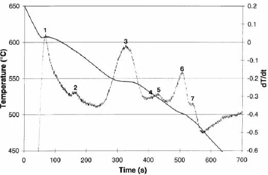
Fig. 2.4 shows the cooling curve and its first derivative obtained from the A319 alloy while Table 2.1 presents its typical solidification sequence. As listed in Table 2.1, when the Al–Si alloy solidifies, the primary aluminum forms and grows in dendrites (hypoeutectic) or silicon phase forms and grows in angular primary particles (hypereutectic). When the eutectic point is reached, the eutectic Al–Si phases nucleate
and grow until the end of solidification. The formation temperature of α-Al dendrite, eutectic Si and eutectic Al2Cu are relatively fixed and independent with alloy
composition. For various other intermetallics in alloys with complex compositions, whether these phases form and their corresponding formation temperatures are dependent on many parameters such as alloy composition, cooling rate during solidification [21].
Fig. 2.4 Temperature-time cooling curve and its first derivative obtained from A319.2 alloy+0.6 wt. % Mg [21].
2 600-572.7 precipitation of pre-eutectic Fe phases 3 561.8 precipitation of eutectic Si phase 4 550-541 precipitation of post eutectic β-Al5FeSi
5 510 precipitation of Mg2Si
6 510 precipitation of Al2Cu
7 502.7 precipitation of Al5Mg8Cu2Si6
Among all the intermetallics in Al-Si alloys, Al2Cu is probably one of the most
important to potentially strengthen the alloys after proper heat treatment. However, the melting point for eutectic Al2Cu is relatively lower in Al–Si alloy (~510oC), thus it
is very important to take it into account when selecting optimal solution heat treatment temperature without causing incipient melting. There are two types of Al2Cu intermetallics, namely fine eutectic Al2Cu and blocky Al2Cu. The presence of
nucleation sites or high cooling rates during solidification can result in fine Al2Cu
particles, which can dissolve within 8 hrs of solid solution at 490℃ [22]. Whereas, the blocky Al2Cu phases are difficult to dissolve during solid solution heat treatment
[23].
In Al–Si cast alloy containing Mg, large amount of Mg2Si intermetallics can be
Al–Si–Cu–Mg alloys with high content of Mg is also reported in reference [24]. With the presence of Fe and Si, it can form π-Al8Mg3FeSi6 phase through L +
β-Al5FeSi→Al + Si + Al8Mg3FeSi6 [25]. The morphologies of Mg2Si, π-Al8Mg3Si6Fe
and Q-Al5Cu2Mg8Si6 are also shown in Fig. 2.3.
2.2.2 Fe-rich intermetallics
Fe is the most common impurity in Al–Si cast alloys. Common sources of Fe in cast alloys are from (i) casting processes, (ii) primary metal and master alloys, (iii) iron tools and equipment used during melting, transferring and casting, and (iv) recycled materials melting equipment and from re-melted scrap castings [26]. Fe level is usually restricted to below 0.15 wt.% in commercial Al–Si cast alloys [27]. However, if Fe presents in the alloy, many different Fe intermetallics can precipitated in the alloys. This section deals with the Fe intermetallics and the modification of β-Al5FeSi intermetallics.
Fe-rich intermetallics
The solubility of Fe is approximately 1.8 wt. % at 655°C in liquid pure Al but only 0.0052 wt. % at 450°C in solid pure Al [28]. Therefore, almost all Fe element precipitate from liquid Al in the form of various Fe-rich intermetallics during solidification. Many Fe-rich intermetallics have been reported for different Al alloys, e.g., Al3Fe, Al6Fe, AlmFe, and Al7Cu2Fe [29-34]. In Al-Si cast alloys, α-AlSiFe,
β-Al5FeSi, and π-Al8FeMg3Si6 (with the presence of Mg in the alloy) are the most
commonly reported Fe intermetallics [2]. With the presence of Mn and Cr, the α-AlSiFe phases can also appear as Al15(Mn,Fe)3Si2 or Al15(Mn,Cr,Fe)3Si2 [27]. In
addition to their different constituents between α-AlSiFe and β-Al5FeSi, their
morphologies also have their unique characteristics: α-AlSiFe appears in the form of Chinese script under microscopy, as is seen in Fig.2.5(a). Whereas, β-Al5FeSi has
platelet morphology (in three dimensions) and appears as a needle in micrograph [35], as is seen in Fig.2.5(b).
Fig.2.5 Microstructures of the two different types of Fe intermetallic phases in the Type 319 aluminum alloy: (a) Chinese script α-phase and (b) needle
β-Al5FeSi phase [36].
According to Table 2.1, the Fe- and Mn- containing phases, e.g., the α-Al15Mn3Si2 and β-Al5FeSi intermetallics precipitate during different stages of
solidification. α-Al15Mn3Si2 intermetallics normally precipitate after the formation of
initial α-Al dendrites but before the appearance of the Al–Si eutectic. If high Fe and Mn levels are present in the alloy and the cooling rate is low, the α-Al15(Mn,Fe)3Si2
phase will precipitate as a primary phase, in the form of coarse particles termed "sludge," having polygonal or star-like morphologies [37]. On the other hand, the β-Al5FeSi phase usually precipitates as a co-eutectic phase before the precipitation of
Al2Cu and other more complex phases [35].
The effect of Fe on mechanical properties has been one of many hot research fields in Al metallurgy. At present, it is generally agreed that Fe increases hardness and greatly reduces the fracture toughness, ductility, fatigue resistance and impact energy [26]. According to Bonsack [38], any amount of Fe over 0.5 wt.% will be present as Al–Fe silicide in large needles, which increases strength and hardness but slightly reduces ductility. Above 0.8 wt.% Fe, both strength and elongation deteriorate rapidly. In addition, excessive Fe content also imposes deleterious influence on the
machinability. However, Fe up to 1.3 wt.% is reported to be beneficial to die cast parts in terms of improved strength, hardness and low tendency toward hot cracking [39]. Courture et al. [40] stated that the addition of Fe to Al–Si alloys is detrimental to the mechanical properties due to the formation of the brittle β-Al5FeSi intermetallics,
which are very hard, brittle and have relatively low bond strength with the matrix. The β-Al5FeSi of platelet morphology can block metal feeding and consequently generate
many porosities during solidification [41], therefore make alloys more easily fractured under tensile loads [2, 42, 43], leading to the decreased ductility and strength [44]. Generally, the detrimental effect of β-Al5FeSi is largely correlated with the
morphology, size and volume fraction. Hence, the necessity to modify the morphology and limit its diameter is vital for industrial practice of Al-Si alloys. Modification of β-Al5FeSi
The detrimental effect of Fe can be minimized by various techniques: (1) rapid solidification silicon [45, 46], (2) Chemical modification [47], and (3) melt superheating [2]. All above-mentioned methods basically convert the crystallization of the needle-like β-Al5FeSi to the less deleterious Chinese script α-Fe phases [2].
Though each of these approaches has its own advantages and limitations, chemical modification, especially via additions of alloying elements, such as Mn, remains the most common practice in Al metallurgy. Elsebaie et al. [48] reported that the addition of Mn can improves the impact energy values appreciably and decrease in the impact energy values. The addition of specific controlled amounts of Mn can decrease the detrimental effects of β-Al5FeSi platelets through the favourable precipitation of Fe in
the form of the more compact Chinese script α-Al15(Mn,Fe)3Si2 phases. But the
amount of Mn to eliminate the detrimental effect of β-Fe phase is still under debate. Reference [49] reported that an Mn/Fe ratio of 0.5 seems to be sufficient for substitution of β-Al5FeSi by a-Al15(Mn,Fe)3Si2 phases, but other researchers [50]
stated that some β-phases could remain even at higher Mn/Fe ration than 0.5. Recently, Farkoosh et al. [51] stated that Mo can suppress the formation of the brittle β-Al5FeSi
strengthening effects at elevated temperature. This section deals with the mechanisms of three strengthening methods and their applications in Al-Si alloys.
2.3.1 Solid solution strengthening
Solid solution strengthening is an increase in strength by means of solute alloying elements in the matrix. By alloying elements into the Al matrix, depending on their size of the alloying elements, they can form either substitution or interstitial solid solution, as illustrated in Fig. 2.6. In both cases, the overall crystal structure is essentially unchanged. However, these alloying elements in the solution create lattice distortion. The greater the difference in lattice parameter, the higher the local stress fields introduced by alloying. These local stress fields act as a barrier to dislocation movement; hence the solid solution strengthening can be achieved.
The strengthening contribution of the solid solution from solute elements could be calculated according to the equation below:
σ
ss= HC
α Eq. 2.1Fig. 2.6 Schematic models of solid solutions: substitutional solid solution and interstitial solid solution [52].
The strengthening degree is generally proportionally to solute concentration. However, the amount of alloying elements is strictly restricted by the phase diagram so as not to precipitate a new phase [53]. It should also be noted that although nearly every element can solute into Al alloy, only a small fraction of them can exert substantial strengthening effect. In Al alloys, Cu and Mg are the two prominent solutes for solid solution strengthening. Cu and Mg in solid solution of Al–Si–Cu–Mg alloys increase yield strength and ultimate tensile strength. However, the elongation of alloys drops with the addition of Cu and Mg [54].
2.3.2 Precipitation strengthening
The precipitation strengthening is another important hardening mechanism in Al-Si alloys. The precipitation strengthening is achieved by precipitation of fine and large quantity of precipitates, thus hindering the motion of dislocation. For heat treatable Al-Si alloys, the precipitation heat treatment usually involves three consecutive stages: solution treatment, quenching and ageing, as shown in Fig. 2.7. The purpose of solution heat treatment in Al–Si alloy is to: (a) Dissolve Cu and Mg containing intermetallic phases formed during solidification; (b) Homogenize the
Fig. 2.7 Diagram showing the three steps for precipitation hardening [55].
The strengthening effect is closely related with the ability to hinder the motion of dislocations [56]. In precipitation strengthening, it is strongly dependent on the size and distribution of small precipitates. The strength of the precipitates increases with their size as long as they are sheared by dislocations. Further increase of precipitate size makes the shearing processes rather difficult; thus, it is more favourable for the dislocations to pass the precipitates via the Orowan mechanism. As indicated in Fig. 2.8 and Fig. 2.9, small precipitates are normally sheared by moving dislocations (Fig. 2.8). When the precipitates are larger, the moving of dislocation is harder through bypassing the precipitates than by bowing (Orowan mechanism) [23].
Fig. 2.8 Dislocations passing a precipitate by a) shearing and b) looping [57].
The relationship between the applied stress and the dislocation bowing is illustrated in Fig. 2.9, and summed up with the Orowan equation [58]:
∆τy = Gb L⁄ Eq. 2.2
where ∆τy is the increase in yield stress due to the particles, G is the shear modulus of the matrix, b is the Burgers vector of the dislocation, and L is the particle spacing, which is usually considered to be the distance between particles arranged on a square grid in the slip plane.
Fig. 2.9 Dislocation meets undeformable second phase particles: dislocation release at higher stresses may occur by Orowan looping or by cross-slip [58].
Ashby further developed this equation to consider the inter-particle spacing, and the effects of statistically distributed particles. The Ashby–Orowan relationship [59, 60] is given as:
∆τy = 0.84(1.2Gb 2πL⁄ )ln(x 2b⁄ ) Eq. 2.3
Application of the Taylor factor for polycrystalline materials, expressing the microstructural parameters in terms of the volume fraction and real diameter and converting shear stress to tensile stress, yields:
∆σy = (0.538Gbf 1 2 ⁄ X ⁄ )ln(X⁄2b) Eq. 2.4
where∆σy y is the increase in yield strength, G is the shear modulus, b is the
Burgers vector, f is the volume fraction of particles, and X is the real (spatial) diameter of the particles.
Kinetics of precipitates
Usually, the decomposition of precipitates or dispersoids from matrix may be divided into three stages: (i) the formation of nuclei; (ii) the growth of these nuclei.
Stage (i) may occur in one of two ways: homogeneous nucleation through spinodal decomposition, in which small concentration fluctuations lead to a decrease in free energy, the reaction may proceed spontaneously and there is no barrier to nucleation; heterogeneous nucleation in regions of high free energy per atom such as point defects, dislocations, grain boundaries.
J. Robertson et al. [61] presented a kinetic model for Al3Zr dispersoids based on
several assumptions as follows [62]: Al3Zr is the only precipitate; Nucleation occurs
homogeneously within the matrix; growth of Al3Zr particles is controlled by diffusion
of Zr to the particle/matrix interface.
The classical steady state nucleation equation has been used to describe the nucleation rate. The nucleation rate is then given by:
J = N
0KTh
exp (−
G∗+QkT
)
Eq. 2.5where J is the nucleation rate per unit volume. N0 is the number density of nucleation sites which for homogeneous nucleation is equal to the number of Zr atoms per unit volume. G∗ is the activation energy barrier for formation of a critically sized cluster. Q is the activation energy for diffusion of zirconium in aluminium. K and h are the Boltzmann and Planck constants respectively. T is the thermodynamic temperature. G∗ is related to the critical radius and the interfacial energy, σ , according to:
concentration gradient at the interface, r∗is thus given by
r
∗=
2σVaKTln c
c∞α
Eq. 2.7
Where Va is the atomic volume, c is the instantaneous concentration of
zirconium in the matrix and c∞α is the concentration of Zr in the matrix in
equilibrium with Al3Zr assuming a planar interface. Values of c∞αcan be obtained
from the solvus line calculated for the metastable Al3Zr phase in the binary Al–Zr
system.
For spherical particles, the growth rate is given by: dr dt
=
D r c−crα cα′−c∞α′ Eq.2.8Where D is the diffusion coefficient, r the particle radius, crα is the
concentration of Zr in the matrix at the interface and cα′ the concentration of
zirconium in the particles. cα′ is calculated from c∞α′ using the Gibbs–Thompson equation, which for the general case may be expressed as
C
rα= C
∞αexp(
2σVakT 1
r
)
Eq.2.9The diffusion coefficient of zirconium in aluminum was calculated at a given temperature from:
D = D
0exp
−QRT Eq. 2.10
Where R is the gas constant. The values forD0 and Q used were 0.0728 m2s-1
and 242 KJ mol-1, respectively. Precipitates in Al-Si cast alloys
Due to the complexity of elements in Al-Si alloy, different precipitates can form, and the section describes several common precipitates in Al-Si cast alloys, and their strengthening effect of Al-Si alloys.
Mg2Si precipitates
Mg2Si precipitate is one of the very common precipitates in Al-Si alloys if Mg is
also present in the alloy. The supersaturated solid solution decomposes to form the metastable precipitates designated GP zone, β'', β' until equilibrium β. The precipitation sequence is generally described as follows [63], solute clusters → GP
zones (spherical)→β''(needle)→β'(rod)→β. The typical size of needle β'' is around 4 * 4 *50 nm3 [64]. Further overageing transforms the needle β'' into thick rods β'. The
β' phase forms as rods of approximately 10 * 10 *500 nm3 [65]. The β equilibrium
phase is found to be plates with dimensions of several micrometers with composition Mg2Si [66].
The typical TEM micrograph of β'' and β' precipitates and their corresponding Selected area diffraction pattern (SADP) are shown in Fig. 2.10 and Fig. 2.11 respectively [67]. As is seen, they are coherent or semicoherent with Al matrix, thus the strenghening effect can be obtained. In Al-Si alloys with Cu, Mg additions, the optimal strength is often achieved through strengthening of various types of precipitates. Ouellet et al. [68] reported a hardening peak caused by the cooperative precipitation of Al2Cu and Mg2Si phases in Al–Si–Cu–Mg alloys. It has been found
that the type of precipitation in the Al–Cu–Mg–Si alloys depends on Mg contents as well as on the Cu:Mg ratio in solid solution. For a Cu:Mg ratio of 2.0 (at. %),
Fig. 2.10 Typical β''precipitates and its corresponding SADP [67].
Fig. 2.11 Typical β'precipitates and its corresponding SADP [67].
Besides, metastable Mg2Si precipitates have positive effect on the nucleation of
dispersoids. It was reported that α-Al(Mn,Cr,Fe)-Si dispersoids heterogeneously nuclear on β'-Mg2Si in 6xxx alloys [71]. As shown in Fig. 2.12, an intermediate phase
u-phase nucleated on the β'-Mg2Si. With continued annealing, α-Al(Mn,Cr,Fe)-Si
dispersoids nucleated heterogeneously on the ‘u-phase’ precipitates before these precipitates dissolved [24, 71, 72].
(a) (b) Fig. 2.12 (a) TEM image of dispersoid nucleated on the surface of u-phase (b) a
model of the precipitation of the dispersoids [71].
Al2Cu precipitates
Cu is one of the most common alloying elements to improve mechanical properties in Al-Si alloys. Cu addition improves strength and hardness of Al–Si alloys in both as-cast and heat-treated conditions [73]. Al-Si alloys containing 4 to 6 wt.% Cu respond most strongly to heat treatment and can reach high strength and ductility [54]. The strengthening effect comes from the decomposition of supersaturated Cu solid solution to form various metastable precipitates. The Al2Cu precipitation
sequence is generally described as follows [63],
(
)
'' '
2 ss GPZones Al Cu
Fig. 2.13 Unit cells of α–Al matrix and θ'', θ' and θ intermetallic phases [74].
The precipitation sequence starts with the decomposition of the supersaturate solid solution and the clustering of Cu atoms; the clustering then leads to formation of coherent, disk-shaped GP zones. These zones manifest as two-dimensional Cu-rich disks with diameters of approximately 3-5 nm. With prolonged time, the GP zones increase in number while remain relatively constant in size. If the ageing temperature increase, the GP zones dissolve and are replaced by metastable precipitates θ''. This precipitate is a three-dimensional disk-shaped plate having an ordered tetragonal arrangement of Al and Cu atoms; θ'' also appears to nucleate uniformly in the matrix and is coherent with matrix. As ageing proceeds, the θ'' starts to dissolve, and θ' commences to form by nucleating on heterogeneously on dislocations or other defects [75] (Fig. 2.14b). θ' also has a plate-like shape and is composed of Al and Cu atoms in an ordered tetragonal structure [23, 57]. However, θ' precipitates grow on further ageing by diffusion of atoms from the supersaturated solid solution to the precipitates [76]. The precipitates continue to grow in accordance with Ostwald ripening [77]. The larger precipitates coarsen as the smaller ones dissolve. As the precipitates grow, the coherency strain increases until interfacial bond strength is exceeded, and the precipitates become non-coherent. So last to form is the non-coherent equilibrium phases (θ), which is completely incoherent with the matrix. In fact, combined with its relatively large size and coarse distribution, the formation of θ reduces the strength
significantly [57]. It should be noted that the best strengthening is obtained when θ'' is the main strengthening phase [57].
Fig. 2.14 (a) Bright-field transmission electron microscope micrograph depicting GPII in the <100>Al zone obtained after aging at 438 K for 8 h; (b) the θ' precipitates in the<100>Al zone observed after aging at 463 K for 8 h [75].
When alloy is solution treated and aged at lower temperature, the uniformly distributed θ" precipitates present. Typical bright field image and its corresponding SADP are presented in Fig. 2.15.
Fig. 2.15 a) Bright field electron micrograph of 2219 after 4.7 d aging at 130oC.
(b) Corresponding selected area diffraction pattern [78].
When solution treated alloys were aged at higher temperature, θ' precipitates present. Fig. 2.16 shows the typical θ' morphology and its corresponding selected area diffraction pattern.
Fig. 2.16 (a) Bright field electron micrograph of θ', (b) Corresponding selected area diffraction pattern [78].
2.3.3 Dispersoid strengthening
Dispersoid strengthening is a very important strengthening method in Al-Si alloys especially at elevated-temperature. Since dispersoids are usually large in size and hard thus the mechanism for dispersoid strengthening can be explained by the
Orowan mechanism discussed in previous section.
Dispersoid strengthening is often desired for elevated-temperature application, as fine precipitates that formed during solution treatment and ageing can be coarsened, resulting in poor elevated-temperature properties [72]. However, dispersoids are usually precipitated during annealing process in which temperature is significantly higher than ageing temperature, thus their thermal stability is better than precipitates which formed during relatively lower temperature (~200oC) [79].
Alloying elements to form dispersoids is increasingly becoming a common practice. However, elements that can be potentially applied to produce castable and dispersoid-strengthening aluminum alloys with high-temperature stability and strength must [80, 81]:
1) Be capable of forming a suitable strengthening dispersoids, and contain a large volume fraction, which must be thermodynamically stable and difficult to shear by dislocations at the intended service temperature. These precipitated phases should also exhibit a similar crystal structure, and a low lattice parameter mismatch with the Al solid solution.
2) Show low solid solubility in Al matrix: A low equilibrium solid solubility at the intended service temperature is necessary to retard volume diffusion-controlled coarsening and prevent dissolution of the precipitated phases. By the lever rule, limited solid solubility also maximizes the equilibrium volume fraction of the dispersoids.
3) Low diffusivity in Al matrix. Limited diffusivity of the solutes in Al should also limits volume diffusion-controlled coarsening, allowing the dispersoids to remain effective barriers to dislocation motion at elevated temperatures. 4) Retain the ability for the alloy to be conventionally solidified.
can dissolve in the Al matrix during the solidification, forming a supersaturated solid solution. During homogenization, α-Al(Mn,Fe)Si dispersoids precipitate from the Al matrix. Study [82] investigated the precipitation behaviour of α-Al(Mn,Fe)Si dispersoids and their effect on mechanical properties during precipitation treatment. Fig. 2.17 shows the precipitation of dispersoids in 3xxx alloy treated at 375 °C for 24 h and their corresponding SADP, and a significant dispersion strengthening effect caused by the precipitation of fine uniformly distributed α-Al(Mn,Fe)Si dispersoids during precipitation treatment is achieved [82].
Fig. 2.17 Type of morphology of dispersoids: (a) SEM and (b) TEM image and SADP along [211]Al (c) as well as the TEM-EDS results of dispersoids (d) in the
sample treated at 375 °C for 48 h [82].
In addition, α-Al(Mn,Fe)Si are confirmed to heterogeneously nucleated on the pre-precipitated Mg2Si needles [24, 71, 72], leading to the large number density in the
matrix. The diffraction pattern of α-Al(Mn,Fe)Si dispersoids are also shown in
Fig. 2.18 which is confirmed to be coherent with the matrix [83]. The size of the α-Al(Mn,Fe)Si is reported to be in the range of 60-100nm [24, 71, 72]. Thus,
pronounced strengthening can be achieved via formation of fine and large number density of α-Al(Mn,Fe)Si dispersoids [84].
Fig. 2.18 Diffraction patterns of α-dispersoids in 3003 alloy after heating to 500 °C [83].
Mo is a transition metal of the sixth group in the periodic table, which is traditionally used as an alloying element for high-strength stainless steels [85]. However, it has not received much attention regarding Al alloys, except few applications in the rapid-solidification powder metallurgy for elevated temperature properties [85-88]. Al–Mo binary phase diagram (Fig. 2.19) shows Mo can promote many AlxMo phases during solidification [89-92]. Mo is also reported to possess low
Fig. 2.19 Al–Mo phase diagram [91].
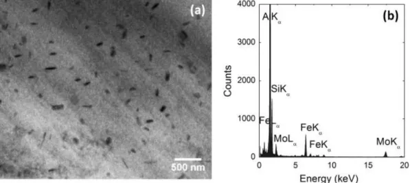
Mo has been applied in Al–Si 356 cast alloy to promote Mo-containing
dispersoids [51, 93]. Mo addition helps to form thermally stable nano-scale α-Al(Mo,Fe)Si dispersoids (Fig 2.20), which leads to higher mechanical properties at
elevated temperature [51]. Farkoosh et al. also employed combined addition of Mo and Mn in one Al–Si–Cu–Mg cast alloy to form large volume of thermally stable
α-Al(Mn,Mo,Fe)Si dispersoids, resulting in more uniform distribution of α-Al(Mn,Mo,Fe)Si dispersoids and elimination of dispersoid free zone (DFZ), due to
the opposite partitioning of the Mo and Mn solute atoms during solidification (shown in Fig. 2.21) [93]. In summary, Mo can form a large amount of metallurgical stable dispersoids in Al–Si cast alloys even when added at low levels [51, 92, 94, 95], make it a promising element as α-Al(Mn,Mo,Fe)Si dispersoid former. These dispersoids are thermally stable, hence, significant enhancement in mechanical properties at elevated temperature including the strength and creep resistance was achieved [51, 72, 93].
Fig 2.20 (a) Bright field TEM micrograph showing the Al(Mo,Fe)Si dispersoids in the interdendrite regions of the MG3R3M alloy formed after 10 h of solution
treatment at 540 °C. (b) EDS spectrum of the Al(Mo,Fe)Si dispersoids [51].
5)
Fig. 2.21 EDS elemental line scanning across a dendrite cell showing the concentration gradients of Mo and Mn (microsegregation) in the as-cast
2.4 Creep behaviour and its mechanism
Creep is a permanent deformation of materials under constant load and at constant temperature. It can occur as a result of long-term exposure to high levels of stress that are still well below the yield strength of the material.
2.4.1 Creep stages
Generally, for tensile creep test, there are three different stages as shown in Fig. 2.22. The primary creep stage is characterized with very high strain rate due to the material elastically and plastically responds to the applied load. As the deformation continues, the material is continually strengthened by work hardening, which leads to the gradual decrease of the creep rate. As the deformation continues, primary creep stage gradually transits into the secondary creep stage. This stage is also called the steady-state creep. The creep rate remains nearly unchanged for a prolonged period under a constant load. This is an interplayed result between recovery and hardening. The secondary creep region usually dominates most of the time of creep deformation. As creep proceeds, the secondary creep changes into the third stage (tertiary creep). Tertiary creep only occurs in tensile creep test. As continuous deformation produces voids or internal cracks which decrease the cross-section hence increase the stress. As a result, a necking occurs at tertiary stage of the creep, which ends up the fracture of the materials (Fig. 2.22). The tertiary stage creep possesses a much higher creep rate.
For compression creep curves, there is no such necking as occurred in tensile creep tests, due to the geometric effect that the sample cross-section swelled as the deformation continues. Thus, the steady-state creep stage dominated during compression creep. As shown in Fig. 2.22 (dotted lines), no tertiary creep can be observed during compression creep test.
Fig. 2.22 Typical creep curve showing the three steps of creep (The dotted line shown in the figure is for the compression creep curves) [70].
2.4.2 Parameters of creep properties
Many researchers [96, 97] proposed many equations to evaluate creep properties of metals and alloys. These equations summarized the total strain and time dependent creep rates. When the creep strain and temperature are lower, the creep strain [98] can be expressed as:
ε(t) = (KT λ⁄ ) ln(1 + t τ⁄ ) Eq. 2.11
whereλand τare constant, T is the experimental temperature. KT λ⁄ and τ are determined by experimental condition. When creep is controlled by dislocation motion, the minimum strain rateεm of dispersoid-strengthened Al alloys can be described by a power-law equation [99]:
![Fig. 2.13 Unit cells of α–Al matrix and θ'', θ' and θ intermetallic phases [74].](https://thumb-eu.123doks.com/thumbv2/123doknet/7491046.224474/44.892.142.753.112.349/fig-unit-cells-α-al-matrix-intermetallic-phases.webp)
![Fig. 2.18 Diffraction patterns of α-dispersoids in 3003 alloy after heating to 500 °C [83]](https://thumb-eu.123doks.com/thumbv2/123doknet/7491046.224474/50.892.181.727.117.662/fig-diffraction-patterns-α-dispersoids-alloy-heating-c.webp)
![Fig. 2.22 Typical creep curve showing the three steps of creep (The dotted line shown in the figure is for the compression creep curves) [70]](https://thumb-eu.123doks.com/thumbv2/123doknet/7491046.224474/54.892.170.739.117.515/typical-creep-curve-showing-dotted-figure-compression-curves.webp)
![Fig. 2.24 The steady-state temperature distribution within a high-performance piston obtained by FE simulation [108]](https://thumb-eu.123doks.com/thumbv2/123doknet/7491046.224474/59.892.150.753.552.791/steady-state-temperature-distribution-performance-piston-obtained-simulation.webp)
![Fig. 2.26 The Al–rich end of the Al-Cu phase diagram showing the metastable GP zone, θ" and θ' solvus temperature [111]](https://thumb-eu.123doks.com/thumbv2/123doknet/7491046.224474/63.892.152.745.535.1090/fig-rich-phase-diagram-showing-metastable-solvus-temperature.webp)
![Fig. 2.28 Transmission electron micrograph from alloy after 2400 h at 250 o C. The electron beam is parallel to [001] α and several large blocky and rod-like precipitates are observed](https://thumb-eu.123doks.com/thumbv2/123doknet/7491046.224474/64.892.159.739.436.747/transmission-electron-micrograph-electron-parallel-blocky-precipitates-observed.webp)
![Fig. 2.29 Bright field TEM image of rod-like equilibrium β-Mg 2 Si precipitates and its corresponding SADP [67]](https://thumb-eu.123doks.com/thumbv2/123doknet/7491046.224474/65.892.138.729.312.537/fig-bright-field-image-equilibrium-precipitates-corresponding-sadp.webp)