is an open access repository that collects the work of Arts et Métiers Institute of
Technology researchers and makes it freely available over the web where possible.
This is an author-deposited version published in: https://sam.ensam.eu
Handle ID: .http://hdl.handle.net/10985/19667
To cite this version :
Hocine CHALAL, Farid ABED-MERAIM - Simulation of Structural Applications and Sheet Metal Forming Processes Based on Quadratic Solid–Shell Elements with Explicit Dynamic Formulation -International Journal of Applied Mechanics - Vol. 11, n°09, p.1950082 - 2019
Any correspondence concerning this service should be sent to the repository
1
SIMULATION OF STRUCTURAL APPLICATIONS AND SHEET METAL FORMING PROCESSES BASED ON QUADRATIC SOLID−SHELL ELEMENTS
WITH EXPLICIT DYNAMIC FORMULATION
HOCINE CHALAL*
Laboratory LEM3, Université de Lorraine, CNRS, Arts et Métiers ParisTech, F-57000 Metz, France hocine.chalal@ensam.eu
FARID ABED-MERAIM
Laboratory LEM3, Université de Lorraine, CNRS, Arts et Métiers ParisTech, F-57000 Metz, France farid.abed-meraim@ensam.eu
In this work, nonlinear dynamic analysis of thin structures is investigated using quadratic solid−shell (SHB-EXP) elements. The proposed SHB-EXP elements are based on a fully three-dimensional formulation using an in-plane reduced-integration scheme along with the assumed-strain method in order to alleviate most locking phenomena. These developments consist of a twenty-node hexahedral element, denoted SHB20-EXP, and its fifteen-node prismatic counterpart, denoted SHB15-EXP. The formulation of these elements is combined with fully three-dimensional behavior models, including elastic behavior as well as anisotropic plastic behavior for metallic materials. The resulting formulations are implemented into the ABAQUS explicit/dynamic software package in the framework of large displacements and rotations. First, to assess the performance of the SHB-EXP elements, four representative nonlinear dynamic benchmark tests have been conducted. Then, impact / crash problem and deep drawing of cylindrical cup have been performed to demonstrate the capabilities of the SHB-EXP elements in handling various types of nonlinearities (large strains, anisotropic plasticity, and double-sided contact). Comparisons with results obtained by ABAQUS elements as well as with reference solutions taken from the literature show the good capabilities of the developed quadratic SHB-EXP elements for the explicit dynamic simulation of thin structures. Keywords: Finite elements; quadratic solid−shell elements; explicit dynamic analysis; 3D simulations; thin structures; sheet metal forming.
1. Introduction
Thin structures are increasingly used in many engineering applications, and especially in automotive industries. These structures are usually modeled by the finite element method using conventional shell elements for both linear and nonlinear problems (see, e.g., [Berg
et al., 2009], [Lampeas and Fotopoulos, 2015], [Cui and Tian, 2017] and [Lei et al.,
2017]). However, for the three-dimensional (3D) simulation of sheet metal forming processes, shell elements have some drawbacks associated with their formulations: plane-stress assumptions; no thickness variations since only the mid-plane of the sheet is
modeled; difficulty in handling double-sided contact, etc. To overcome the latter issues associated with shell elements, continuum solid elements are alternatively used to allow more realistic modeling of structural applications thanks to their 3D formulation, thus avoiding geometric (mid-plane) or kinematics assumptions, as well as constitutive (plane-stress) restrictions. However, the use of solid elements for the simulation of thin structures requires very fine meshes to obtain accurate solutions due to the various locking phenomena that are inherent to these elements (see, e.g., [Feng et al., 2012] and [Wang and Shi, 2017]). Moreover, in explicit dynamic simulations of thin structures using solid elements, the time step depends on the smallest element size, the latter often being in the thickness direction, which may lead to very high computational costs.
In order to obtain accurate and reliable numerical results, with respect to traditional shell and solid elements, the solid−shell elements have been developed during the last decades. They are based on a fully 3D formulation with only displacements as degrees of freedom. Combined with the reduced-integration technique, various methods have been proposed in the literature to eliminate most locking phenomena (see, e.g., [Cho et al., 1998], [Hauptmann and Schweizerhof, 1998], [Abed-Meraim and Combescure, 2002, 2009], [Xie et al., 2015] and [Wang and Shi, 2017]), among which the assumed-strain method (ASM), the enhanced assumed strain (EAS) formulation, and the assumed natural strain (ANS) approach.
In the context of dynamic and vibration analyses of thin structures with solid−shell elements, Pagani et al. [2012, 2014] and Cocchetti et al. [2013] have developed a low-order solid−shell element, in which an efficient selective mass scaling method has been introduced in order to control the critical time step. Hajlaoui et al. [2017] have proposed an 8-node hexahedral solid−shell element for the nonlinear dynamic analysis of functionally graded materials (FGM). With this element, a quadratic distribution of the shear stress through the thickness is considered, which allows enhancing the dynamic behavior of FGM shell structures. Based on the method of incompatible modes for conventional solid elements, Mattern et al. [2015] have proposed a solid−shell element with linear interpolation, as an alternative to the well-known EAS technique, for explicit dynamic simulations using symbolic programming.
In this work, prismatic and hexahedral solid−shell elements with quadratic interpolation of displacements, denoted SHB15-EXP and SHB20-EXP, respectively, are proposed for the nonlinear dynamic simulation of 3D thin structures. These two formulations are developed starting from earlier works on the family of solid−shell (SHB) elements, which includes linear solid−shell elements and their quadratic counterparts (see [Abed-Meraim and Combescure, 2002], [Abed-Meraim and Combescure, 2009], [Trinh et al., 2011], [Salahouelhadj et al., 2012], [Abed-Meraim et
al., 2013], [Wang et al., 2017a, 2017b]). The quadratic versions of the SHB elements, which have been first developed in the framework of small strain and quasi-static analysis, are extended in the current work to the explicit dynamic framework. The motivation behind this extension is to allow analyzing all types of structural problems (e.g., impact/crash, complex sheet metal forming processes), which cannot be modeled
with the previously developed quasi-static/implicit versions of the SHB elements, due to convergence issues of implicit solvers.
The remainder of the paper is organized as follows. The explicit dynamic formulation of the quadratic SHB-EXP solid−shell elements is first presented in Section 2. In Section 3, the performance of the quadratic SHB-EXP elements is first evaluated through the simulation of nonlinear dynamic benchmark problems. Then, more complex and challenging applications are considered to assess the performance of the SHB-EXP elements in severe dynamic elasto-plastic problems. Finally, the main conclusions and remarks are drawn in Section 4.
2. Formulation of the SHB-EXP Elements
2.1. Reference geometry and location of integration points
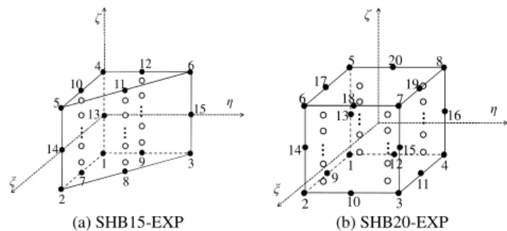
The proposed SHB-EXP elements are based on a fully 3D formulation using an in-plane reduced-integration scheme. Figure 1 shows the reference geometry of the quadratic prismatic SHB15-EXP and hexahedral SHB20-EXP solid−shell elements as well as the location of their integration points. The local direction ζ is considered as the thickness direction, where an arbitrary number of integration points are distributed.
1 2 3 4 5 6 ζ ξ η 10 12 7 8 9 13 14 15 11 … … … 1 2 4 3 5 6 7 8 ζ ξ η 9 10 11 12 17 18 19 20 13 14 15 16 … … … …
(a) SHB15-EXP (b) SHB20-EXP
Fig. 1. SHB-EXP solid−shell elements: reference geometry and location of the associated integration points. 2.2. Discrete gradient operator and internal forces
Using standard interpolation functions for traditional continuum prismatic and hexahedral elements, the complete expression of the velocity field vi for the SHB-EXP elements can
be written as follows:
0 1 1 2 2 3 3 1 1
i i i i i i i
v =a +a x +a x +a x +c h + +⋯ c hα α with i=1, 2, 3 , (1) where hα are functions of the local coordinates
ξ η ζ
, ,
, in the reference coordinate system, and α varies from 1 to 11 for the SHB15-EXP element, and from 1 to 16 for the SHB20-EXP element. Note that the expressions of the hα functions can be found in [Wang et al., 2017b], where the quasi-static/implicit formulations of the quadratic SHB elements have been detailed.Using the same expansion as for the velocity field (1), the complete expression of the nodal velocity vectors dɺi can be expressed by the following compact form:
0 1 1 2 2 3 3 i =ai +ai +ai +ai +
αcαi α dɺ s x x x h with i=1, 2, 3 , (2) where(
1, 2, 3, ,)
T i = xi xi xi xiKx ⋯ are the nodal coordinate vectors. In Eq. (2), index α ranges from 1 to 11 for the SHB15-EXP element, and from 1 to 16 for the SHB20-EXP element. Also, vector T =
(
1, 1, , 1)
s ⋯ has fifteen constant components in the case of the SHB15-EXP element, and twenty constant components for the SHB20-EXP element.
With the help of some well-known orthogonality conditions and of the Hallquist [1983] vectors | 0 i i x ξ η ζ= = = ∂ = ∂ N
b , where vector N contains the expressions of the interpolation functions NI, the unknown constants aji and cαi in Eq. (2) can be derived
as:
, ,
T T
ji j i i i
a =b ⋅d cα =γα⋅d (3) where the complete details on the expressions of vectors γα can be found in [Wang et
al., 2017b].
By introducing the discrete gradient operator B, the vector form of the velocity gradient operator can be expressed as follows:
( )
, , , , , , , , , , x x y y x z z s y x y y x z y z z y x z z x v v v v v v v v v ∇ = + = ⋅ = ⋅ + + d v B d B d d ɺ ɺ ɺ ɺ (4)where the expression of the discrete gradient operator B is: , , , , , , , , , . T T x x T T y y T T z z T T T T y y x x T T T T z z y y T T T T z z x x h h h h h h h h h α α α α α α α α α α α α α α α α α α + + + + + + + + + b 0 0 0 b 0 0 0 b B = b b 0 0 b b b 0 b γ γ γ γ γ γ γ γ γ (5)
From the simplified form of the Hu–Washizu variational principle (see [Simo and Hughes, 1986]), the expression of the internal force vector of the proposed SHB-EXP elements can be derived as follows:
int , e T d Ω =
⋅ Ω f B σ (6)where σ is the Cauchy stress tensor.
To solve explicit dynamic problems with the proposed SHB-EXP elements, a diagonal lumped element mass matrix is added to the above formulations for the prismatic and hexahedral SHB-EXP elements. These lumped mass matrices are defined in the reference coordinate system (see [Zienkiewicz et al., 2006] and [Wang et al., 2017a] for more details).
2.3. Local coordinate frames
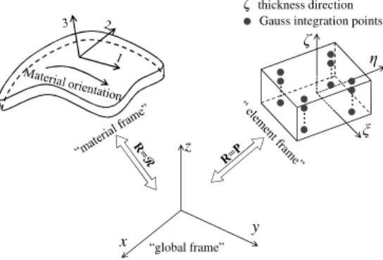
In the framework of large strains, the formulation of the SHB-EXP elements requires the definition of two local frames with respect to the global coordinate system for the calculation of the internal forces associated with the constitutive law, as illustrated in Fig. 2. The first type of local frame, which is denoted as the “element frame”, is attached to the element mid-plane associated with each integration point. In these local physical coordinate systems, where the ζ -coordinate represents the thickness direction, the fourth-order elasticity tensor is specified. The second local frame is called the “material frame”, in which the anisotropic plastic behavior of the material is defined. This material frame is also used to integrate the resulting constitutive equations in order to ensure the incremental objectivity of the model.
z y x “global frame” ... η ξ ζ ... ... ... ζthickness direction Gauss integration points
Fig. 2. Definition of the local frames with respect to the global coordinate system for the proposed SHB-EXP elements.
3. Numerical examples
The resulting quadratic SHB-EXP elements have been implemented into the finite element code ABAQUS using the explicit dynamic solver. First, four representative nonlinear dynamic problems have been conducted in order to assess the performance of the SHB-EXP elements. Then, impact / crash problem and deep drawing of cylindrical cup have been performed to demonstrate the capabilities of the SHB-EXP elements in
handling various types of nonlinearities (large displacements and rotations, anisotropic plasticity, and double-sided contact).
For comparison purposes, all numerical results obtained with the SHB-EXP elements are compared with those given by ABAQUS linear elements, using the same in-plane meshes, along with reference solutions taken from the literature. Note that the following simulations are achieved using only a single element layer with two integration points through the thickness in the case of SHB-EXP elements. Furthermore, since no quadratic elements are available in the ABAQUS/Explicit software package, standard quadratic prismatic and hexahedral solid elements (i.e., 15-node solid element and 20-node solid element, respectively) have been implemented into the finite element code ABAQUS/Explicit for consistent comparisons with the proposed quadratic SHB-EXP elements. It is worth noting that the ABAQUS linear prismatic solid element (i.e., C3D6) is provided with a single integration point in the explicit dynamic code ABAQUS (see Table 1 for the description of all finite elements used for comparison purposes). Therefore, in what follows, several element layers are required for the ABAQUS linear prismatic solid element C3D6 in order to have the same number of integration points in the thickness direction as the other elements used for comparison.
In the following benchmark problems, the structures are meshed using a specific nomenclature for each type of finite element. This nomenclature is detailed in Table 2.
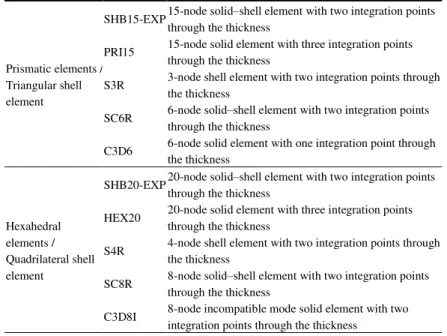
Table 1. Prismatic, hexahedral as well as shell finite elements used in the simulations.
Prismatic elements / Triangular shell element
SHB15-EXP 15-node solid‒shell element with two integration points through the thickness
PRI15 15-node solid element with three integration points through the thickness
S3R 3-node shell element with two integration points through the thickness
SC6R 6-node solid‒shell element with two integration points through the thickness
C3D6 6-node solid element with one integration point through the thickness
Hexahedral elements / Quadrilateral shell element
SHB20-EXP 20-node solid‒shell element with two integration points through the thickness
HEX20 20-node solid element with three integration points through the thickness
S4R 4-node shell element with two integration points through the thickness
SC8R 8-node solid‒shell element with two integration points through the thickness
C3D8I 8-node incompatible mode solid element with two integration points through the thickness
Table 2. Description of the mesh strategy used in the simulations. N1:Number of elements along the length
N2: Number of elements along the width
N3: Number of elements along the thickness
Triangular shell elements Prismatic elements Quadrilateral elements Hexahedral elements N1×N2×2 (N1×N2×2)×N3 N1×N2 (N1×N2)×N3
3.1. Cantilever beam subjected to concentrated force
The first explicit/dynamic problem consists of a simple cantilever beam subjected to a concentrated force at its free end. The geometry and the elastic properties of the beam are summarized in Fig. 3(a), while Fig. 3(b) illustrates the deformed shape of the cantilever beam with respect to the underformed shape. The dynamic response in terms of deflection history at the free edge of the beam, obtained using the explicit quadratic elements (i.e., standard quadratic solid elements and SHB-EXP elements) as well as ABAQUS explicit linear elements, is shown in Fig. 4 along with the reference solution given by Olovsson et al. [2004]. The results reveal that the solution yielded by the proposed SHB-EXP elements is in excellent agreement with the reference solution, which is also the case of the S3R, SC6R, S4R, SC8R and C3D8I ABAQUS elements as well as explicit quadratic PRI15 and HEX20 elements. For the linear prismatic ABAQUS solid element (i.e., C3D6), although requiring twice more elements (i.e., two element layers in the thickness direction), it is found that the solution it provides is far from the reference solution, which suggests resorting to very fine meshes for this element to obtain an accurate solution, while only five SHB20-EXP elements or ten SHB15-EXP are sufficient. F = 100 N t = 0.01 m E = 100 GPa v = 0 ρ = 1000 kg/m3
(a)Geometry (b) Undeformed and deformed configurations Fig. 3. Cantilever beam.
0.00 0.02 0.04 0.06 0.08 0.00 0.02 0.04 0.06 0.08 0.10 0.12 SC6R (5×1×2)×1 C3D6 (5×1×2)×2 PRI15 (5×1×2)×1 Olovsson et al. [2004] SHB15-EXP (5×1×2)×1 S3R 5×1×2 D ef le ct io n (m ) Time (s) 0.00 0.02 0.04 0.06 0.08 0.00 0.02 0.04 0.06 0.08 0.10 0.12 SC8R 5×1×1 C3D8I 5×1×1 HEX20 5×1×1 Olovsson et al. [2004] SHB20-EXP 5×1×1 S4R 5×1 D ef le ct io n ( m ) Time (s)
(a) Triangular shell / prismatic elements (b) Quadrilateral shell / hexahedral elements Fig. 4. Deflection history for the cantilever beam.
3.2. Spherical cap under uniform pressure
A dynamic benchmark test of a clamped spherical cap, subjected to a uniform pressure over its top surface, is analyzed in this section. Both elastic and elasto-plastic behavior models are considered, with the material properties given in Fig. 5(a). Figure 5(b) provides an illustration of the deformed shape of the spherical cap with respect to the underformed shape. Owing to the problem symmetry, only one quarter of the structure is modeled. In addition to the mesh nomenclature previously defined, three partitions for the quarter of the spherical cap are created in order to achieve a relatively regular mesh. This leads to the following new mesh nomenclature for this test: 3×(N1×N1)×N3 for hexahedral
elements, where N1 indicates the number of elements along each edge and N3 the number
of elements in the thickness direction (see Fig. 5(c)). For the prismatic elements, the total number of elements is twice that corresponding to hexahedral elements, which leads to 3×(N1×N1×2)×N3 elements. For the quadrilateral shell elements, the nomenclature for
discretizing the quarter model is 3×(N1×N1), while this nomenclature is 3×(N1×N1×2)
when triangular shell elements are used.
In Figs. 6 and 7, the histories of the central deflection of the spherical cap, in the case of elastic and elasto-plastic materials, respectively, are shown. In these figures, the results obtained with the explicit quadratic elements (i.e., PRI15, HEX20 and SHB-EXP elements) are compared with those given by ABAQUS explicit linear elements as well as with the reference solutions given by Bathe et al. [1975] and Belytschko et al. [1984]. From these figures, it can be seen that the results obtained with the proposed quadratic SHB-EXP elements are the closest to the reference solutions along the entire deflection history, while ABAQUS shell elements and the explicit quadratic HEX20 element provide results that deviate from the reference solutions when elastic material and elasto-plastic material are considered, respectively (see Figs. 6(a) and 6(b) for shell elements, and Fig. 7(b) for the HEX20 element). Similar to the previous benchmark test, the results obtained with the ABAQUS linear prismatic solid element (i.e., C3D6) are far from the reference solutions during the second stage of loading (from T = 0.2 s) for both elastic and elasto-plastic materials.
P = 600 t = 0.41 E = 10.5×10⁶ ν= 0.3 ρ= 2.45 ×10⁻⁴ σ 0 = 24000 N1 N1 N1 N1 N1 N1 N1 N1 N1 N3 N3 N3
(a)Geometry (b) Undeformed and
deformed configurations (c) Mesh nomenclature Fig. 5. Clamped spherical cap under uniform pressure.
0.0 0.1 0.2 0.3 0.4 0.5 0.6 -0.12 -0.08 -0.04 0.00 0.04 0.08 PRI15 3×(4×4×2)×1 Bathe et al. [1975] Belytschko et al. [1984] SHB15-EXP 3×(4×4×2)×1 S3R 3×(4×4×2) SC6R 3×(4×4×2)×1 C3D6 3×(4×4×2)×2 C en tr al d is pl ac em en t Time (s) 0.0 0.1 0.2 0.3 0.4 0.5 0.6 -0.12 -0.08 -0.04 0.00 0.04 0.08 C3D8I 3×(4×4)×1 HEX20 3×(4×4)×1 Bathe et al. [1975] Belytschko et al. [1984] SHB20-EXP 3×(4×4)×1 S4R 3×(4×4) SC8R 3×(4×4)×1 C en tral d is pl acem en t Time (×10-3 s)
(a) Triangular shell / prismatic elements (b) Quadrilateral shell / hexahedral elements Fig. 6. Vertical displacement history for the point located at the apex of the clamped spherical cap in the case of elastic material. 0.0 0.1 0.2 0.3 0.4 0.5 0.6 -0.12 -0.08 -0.04 0.00 0.04 0.08 Bathe et al. [1975] Belytschko et al. [1984] SHB15-EXP 3×(4×4×2)×1 S3R 3×(4×4×2) SC6R 3×(4×4×2)×1 C3D6 3×(4×4×2)×2 PRI15 3×(4×4×2)×1 C en tr al d is pl ac em en t Time (s) 0.0 0.1 0.2 0.3 0.4 0.5 0.6 -0.12 -0.08 -0.04 0.00 0.04 0.08 Bathe et al. [1975] Belytschko et al. [1984] SHB20-EXP 3×(4×4)×1 S4R 3×(4×4) SC8R 3×(4×4)×1 C3D8I 3×(4×4)×1 HEX20 3×(4×4)×1 C en tr al d is pl ac em en t Time (s)
(a) Triangular shell / prismatic elements (b) Quadrilateral shell / hexahedral elements Fig. 7. Vertical displacement history for the point located at the apex of the clamped spherical cap in the case of elasto-plastic material.
3.3. Rectangular plate subjected to triangular pulse
The dynamic response of an elastic rectangular plate is considered here. The rectangular plate is simply supported at each edge, and subjected to a uniform pressure having triangular time variation, as shown in Fig. 8(a). Figure 8(b) gives an illustration of the deformed shape of the plate with respect to the underformed shape. Due to the problem symmetry, only one quarter of the plate is analyzed. It is worth noting that only the mid-surface of the lateral edges of the plate is simply supported, which requires meshing the plate with two element layers in the case of ABAQUS linear solid and solid−shell elements (i.e., SC6R, C3D6, SC8R and C3D8I elements). As to the proposed quadratic SHB-EXP elements and standard quadratic PRI15 and HEX20 solid elements, only one element layer is needed to model this benchmark problem, thanks to the existing mid-surface nodes in traditional continuum quadratic elements.
The deflection of the central point of the plate, obtained with the explicit quadratic elements, is depicted in Fig. 9 and compared with the results provided by ABAQUS explicit linear elements as well as with the reference solution given by Sheikh and
Mukhopadhyay [2002]. It can be observed once again that the SHB-EXP elements perform very well with respect to the reference solution, which is also the case for ABAQUS shell, solid−shell and C3D8I elements as well as the explicit quadratic PRI15 and HEX20 elements. However, as pointed out in the previous dynamic benchmark problems, finer mesh is required for the ABAQUS linear prismatic solid element in order to obtain an accurate solution.
z y x A P t=2.54 E=30×106 v=0.3 ρ= 0.00073 P Time (s) 40 0.05 s
(a)Geometry (b) Undeformed and deformed configurations Fig. 8. Simply supported rectangular plate subjected to triangular pulse.
0 2 4 6 8 10 -2 0 2 4 6 8 10 12 14 16 SC6R (10×7×2)×2 C3D6 (10×7×2)×2 PRI15 (10×7×2)×1 Sheikh and Mukhopadhyay [2002]
SHB15-EXP (10×7×2)×1 S3R 10×7×2 C en tr al d is p la ce m en t (× 1 9. 44 4) Time (×500 s) 0 2 4 6 8 10 -2 0 2 4 6 8 10 12 14 16 SC8R 10×7×2 C3D8I 10×7×2 HEX20 10×7×1 Sheikh and Mukhopadhyay [2002] SHB20-EXP 10×7×1 S4R 10×7 C en tr al d is p la ce m en t (× 1 9 .4 4 4 ) Time (×500 s)
(a) Triangular shell / prismatic elements (b) Quadrilateral shell / hexahedral elements Fig. 9. Dynamic response curves for the simply supported rectangular plate subjected to triangular pulse.
3.4. Pinched hemispherical shell
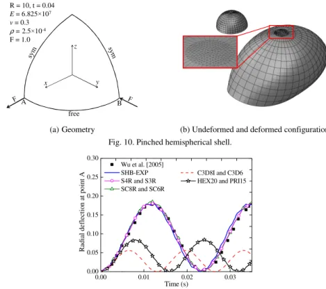
From the above benchmark problems, it can be observed that the simulation results obtained with the SHB15-EXP are comparable to those provided by the SHB20-EXP element. Despite this, the prismatic SHB15-EXP element has been mainly developed for use in mesh discretization of complex geometries, for which regular mesh with hexahedral elements cannot be achieved. To this end, we consider in this section the popular benchmark test of a hemispherical shell that is loaded by alternating radial forces as shown in Fig. 10(a). By considering the symmetry, only a quarter of the structure is discretized. The hemispherical shell is meshed with a mixture of prismatic and hexahedral elements, or triangular and quadrilateral shell elements, which consists of 90 prismatic or triangular shell elements located at the top of the hemisphere (far from the load points, see Fig. 10(b)), and 110 hexahedral or quadrilateral shell elements for the remaining area.
free A B z x y R = 10, t = 0.04 E = 6.825×10⁷ v = 0.3 ρ= 2.5×10⁻⁴ F = 1.0
(a)Geometry (b) Undeformed and deformed configurations Fig. 10. Pinched hemispherical shell.
0.00 0.01 0.02 0.03 0.00 0.05 0.10 0.15 0.20 0.25 0.30 C3D8I and C3D6 HEX20 and PRI15 Wu et al. [2005] SHB-EXP S4R and S3R SC8R and SC6R R ad ia l de fl ec ti on a t po in t A Time (s)
Fig. 11. Radial deflection at point A for the pinched hemispherical shell.
The simulation results obtained with the mixture of SHB-EXP elements, in terms of history of radial deflection at point A, are plotted in Fig. 11, and compared with those given by a mixture of standard explicit quadratic solid elements and a mixture of ABAQUS explicit linear elements, along with the reference solution given by Wu et al. [2005]. Compared to the reference solution, it can be observed that the SHB-EXP elements successfully pass this benchmark test, based on a combination of prismatic and hexahedral solid−shell elements, which is also the case of ABAQUS linear shell and solid−shell elements. However, the results obtained by the combination of standard explicit quadratic solid elements (i.e., PRI15 and HEX20) and a mixture of ABAQUS linear solid elements (i.e., C3D6 and C3D8I) reveal the poor performance of these elements in this test, even when using two element layers in the thickness direction, due to their sensitivity to locking effects.
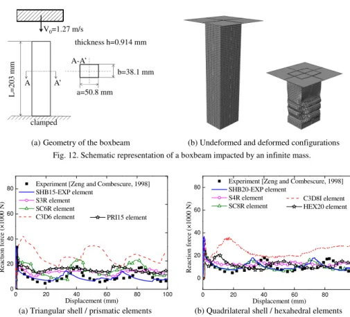
3.5. Impact of a boxbeam
In this complex benchmark problem, a steel boxbeam, clamped at one end as illustrated in Fig. 12(a), is impacted by an infinite mass with a constant velocity of 1.27 m/s. The geometry of the cross-section of the boxbeam is an empty rectangle with a thickness of
0.914 mm. The following Ludwig isotropic hardening law is used in the simulations for the elasto-plastic behavior of the boxbeam:
0 = + N,
Y Y kε (7)
where ε and Y0 are the equivalent plastic strain and the initial yield stress, respectively, while k and N are the hardening parameters. The elasto-plastic material parameters of the boxbeam are reported in Table 3. During the simulations, frictionless contact is considered between the boxbeam and the rigid impactor.
Due to the symmetry, one quarter of the boxbeam is modeled. In the case of hexahedral solid, solid−shell and quadrilateral shell elements, a mesh of 896 elements with a single element layer is adopted, while 1792 elements with a single element layer are used in the case of quadratic prismatic solid and solid−shell elements as well as triangular shell elements. For the ABAQUS explicit linear solid element C3D6, the same in-plane mesh as the prismatic solid−shell element is used, with however two element layers through the thickness.
Figure 13 shows the predicted reaction force−displacement curves for the impactor, as obtained using the SHB-EXP elements, which are compared with the results given by ABAQUS elements as well as explicit quadratic solid elements (i.e., PRI15 and HEX20), along with the experimental results provided by Zeng and Combescure [1998]. The results predicted with the quadratic SHB-EXP elements reveal that the three impact force peaks in the reaction force−displacement curve, which are typical in such impact problems, are in good agreement with experiments. More specifically, the quadratic SHB-EXP elements provide the closest results to the experimental curve, while ABAQUS shell and solid−shell elements provide results that slightly deviate from the experimental curve. As to the explicit quadratic solid elements (i.e., PRI15 and HEX20), although the reaction force is in the order of magnitude of the experimental one, the force peaks are not well reproduced with these elements. Regarding ABAQUS linear solid elements (i.e., C3D6 and C3D8I), the latter provide the farthest results with respect to the experimental curve, and appear to be less suitable for this type of crashworthiness analysis.
Table 3. Elasto-plastic material parameters used in the simulation for the boxbeam. Material E (GPa) ν Y0 (MPa) k (MPa) N ρ (kg / m3)
V0=1.27 m/s L = 2 0 3 m m A A’ a=50.8 mm b=38.1 mm thickness h=0.914 mm clamped A-A’
(a)Geometry of the boxbeam (b) Undeformed and deformed configurations Fig. 12. Schematic representation of a boxbeam impacted by an infinite mass.
0 20 40 60 80 100 0 20 40 60 80 PRI15 element R ea ct io n fo rc e (× 10 00 N ) Displacement (mm) Experiment [Zeng and Combescure, 1998] SHB15-EXP element S3R element SC6R element C3D6 element 0 20 40 60 80 100 0 20 40 60 80 C3D8I element HEX20 element R ea ct io n fo rc e (× 10 0 0 N ) Displacement (mm)
Experiment [Zeng and Combescure, 1998] SHB20-EXP element
S4R element SC8R element
(a) Triangular shell / prismatic elements (b) Quadrilateral shell / hexahedral elements Fig. 13. Reaction force−displacement curves for the impactor.
3.6. Deep drawing of a cylindrical cup
This subsection is devoted to the simulation of deep drawing of a cylindrical cup in order to evaluate the capabilities of the quadratic SHB-EXP elements in modeling sheet metal forming processes. This sheet forming process is commonly used to study the earing profile of the cylindrical cup when anisotropic plastic behavior of sheet metals is considered. The geometry and dimensions of the forming setup are illustrated in Fig. 14. The sheet is made of an Aluminum AA2090-T3 material. The following Swift isotropic hardening law is used in the simulations for the elasto-plastic behavior of the sheet:
(
0)
= N.
Y k ε +ε (8)
Table 4. Elasto-plastic material parameters used in the simulation for the Aluminum AA2090-T3.
Material E (GPa) ν ε0 k (MPa) N AA2090-T3 70.5 0.34 0.025 646 0.227
Fig. 14. Geometry and dimensions (in mm) of the cylindrical cup drawing setup.
The proposed SHB-EXP elements have been combined with the Hill’48 yield surface to account for the initial anisotropy of the sheet. The corresponding Hill’48 anisotropy coefficients are provided in Table 5 (see [Yoon et al., 2006]).
Owing to the problem symmetry, one quarter of the initial sheet is modeled. In the case of hexahedral and quadrilateral shell elements, the quarter of the circular sheet is meshed with 255 elements, while 510 elements are used in the case of prismatic and triangular shell elements. The simulations are performed using only a single element layer for the quadratic solid and solid−shell elements as well as ABAQUS linear solid−shell elements. Note that only two integration points in the thickness direction are sufficient for the quadratic SHB-EXP elements to obtain converged results, while three integration points are considered for the explicit quadratic solid elements. As to the explicit ABAQUS linear solid elements, three integration points are required to obtain converged result, which involves three element layers in the case of the ABAQUS linear prismatic solid element, and two element layers in the case of the ABAQUS linear hexahedral solid element.
(a) SHB15-EXP (b) SHB20-EXP
Fig. 15. Final deformed shape for a completely drawn cylindrical cup.
Figure 15 shows the deformed meshes of the sheet, as obtained with the quadratic SHB-EXP elements, which correspond to a completely drawn cup. It can be seen that the proposed SHB-EXP elements predict four ears for the cylindrical cup, which is consistent
Table 5. Hill’48 anisotropy coefficients for AA2090-T3 aluminum sheet.
Material F G H L M N
with the use of the quadratic Hill’48 yield surface for the description of the material planar anisotropy. The final height profiles for the cylindrical cup, as obtained with the SHB-EXP elements, are reported in Fig. 16 and compared with those provided by the explicit quadratic solid elements as well as ABAQUS explicit elements, along with the experimental ones given by Yoon et al. [2006]. Overall, the shape of the earing profiles predicted with the SHB-EXP elements is in good agreement with the experiments, with the cup heights slightly underestimated at 0° and 90° from the rolling direction, while they are closer to the experiments in the range around the experimental peak value at 50° from the rolling direction. Note that the ABAQUS explicit linear solid element C3D8I as well as the ABAQUS shell and solid−shell elements provide the farthest results with respect to the experimental cup heights in the range around 0°, which emphasizes the limitations of these elements in handling double-sided contact in sheet metal forming processes. 0 10 20 30 40 50 60 70 80 90 35.0 37.5 40.0 42.5 45.0 47.5 50.0 52.5 55.0 C3D6 PRI15 Experiment [Yoon et al., 2006] SHB15-EXP
S3R SC6R
Angle from the rolling direction (deg.)
C up h ei gh t (m m ) 0 10 20 30 40 50 60 70 80 90 35.0 37.5 40.0 42.5 45.0 47.5 50.0 52.5 55.0 C3D8I HEX20 Experiment [Yoon et al., 2006]
SHB20-EXP S4R SC8R
Angle from the rolling direction (deg.)
C u p h ei gh t (m m )
(a) Triangular shell / prismatic elements (b) Quadrilateral shell / hexahedral elements Fig. 16. Prediction of cup height profiles.
The thickness strain distribution along the rolling and transverse directions at the end of the forming process is also analyzed in this problem. Figure 17 compares the predicted and measured thickness strain in both directions. In the rolling direction (see Figs. 17(a) and (b)), the thickness strain distributions predicted with the proposed SHB-EXP elements and quadratic solid elements are in good agreement with the experiments from the center of the sheet to the initial position of 50 mm, which is not the case of ABAQUS solid and solid−shell elements. Beyond this position, the predicted results differ from the experiments for all elements except for the proposed SHB20-EXP, for which the predicted results are the closest to the experimental ones. In the transverse direction (see Figs. 17(c) and (d)), the thickness strain distributions predicted by the proposed SHB15-EXP and PRI15 as well as SHB20-SHB15-EXP and HEX20 are very close to each other. More specifically, from the center of the sheet to the initial position of 50 mm, the results obtained with the prismatic quadratic solid and solid−shell elements are in good agreement with the experiments. However, the thickness strain distributions differ from the experiments beyond the initial position of 50 mm for all elements.
0 10 20 30 40 50 60 70 80 -0.2 -0.1 0.0 0.1 0.2 0.3 0.4 C3D6 PRI15 Experiment [Yoon et al., 2006] SHB15-EXP
S3R SC6R
Initial material position along rolling direction (mm)
T hi ck ne ss s tr ai n 0 10 20 30 40 50 60 70 80 -0.2 -0.1 0.0 0.1 0.2 0.3 0.4 C3D8I HEX20 Experiment [Yoon et al., 2006]
SHB20-EXP S4R SC8R
Initial material position along rolling direction (mm)
T h ic k n es s st ra in
(a) Rolling direction: triangular shell / prismatic elements
(b) Rolling direction: quadrilateral shell / hexahedral elements 0 10 20 30 40 50 60 70 80 -0.2 -0.1 0.0 0.1 0.2 0.3 0.4 C3D6 PRI15 Experiment [Yoon et al., 2006] SHB15-EXP
S3R SC6R
Initial material position along transverse direction (mm)
T hi ck n es s st ra in 0 10 20 30 40 50 60 70 80 -0.2 -0.1 0.0 0.1 0.2 0.3 0.4 C3D8I HEX20 Experiment [Yoon et al., 2006] SHB20-EXP
S4R SC8R
Initial material position along transverse direction (mm)
T h ic kn es s st ra in
(c) Transverse direction: triangular shell / prismatic elements
(d) Transverse direction: quadrilateral shell / hexahedral elements
Fig. 17. Comparison of predicted and measured thickness strain distributions.
4. Conclusions
In this paper, quadratic prismatic and hexahedral solid−shell elements, denoted SHB-EXP, have been proposed for the explicit dynamic modeling of 3D thin structures. These SHB-EXP elements are based on a purely three-dimensional approach, with displacements as the only degrees of freedom. Furthermore, for efficiency requirements and for alleviating locking phenomena, an in-plane reduced-integration scheme along with the assumed-strain method is adopted in the formulations. The resulting formulations are computationally efficient, since only a single layer of elements with an arbitrary number of through-thickness integration points is required to model 3D thin structures. The quadratic SHB-EXP elements have been implemented into the ABAQUS explicit software package, in the framework of large displacements and rotations, for the dynamic simulations of structural applications.
Four representative dynamic benchmark tests, involving geometric and material non-linearities, have been first conducted in order to assess the performance of the SHB-EXP elements. For each benchmark problem, the results given by the proposed SHB-EXP elements have been compared with those yielded by ABAQUS explicit linear elements as well as with reference solutions taken from the literature. In addition, since no quadratic
elements are available in the ABAQUS/Explicit software package, standard quadratic prismatic and hexahedral solid elements (i.e., 15-node solid element and 20-node solid element, respectively) have been implemented in this work into the ABAQUS/Explicit software package for consistent comparison with the quadratic SHB-EXP elements. From these first dynamic analyses, the numerical results obtained with the SHB-EXP elements showed excellent agreement with the available reference solutions. Compared to the implemented standard explicit quadratic solid elements as well as ABAQUS explicit linear shell and solid−shell elements, the performance of the SHB-EXP elements is often comparable, and even better in some cases. However, in most dynamic benchmark tests, the numerical results obtained with the ABAQUS linear prismatic solid element (i.e., C3D6) reveal that this element requires finer mesh (in the plane and through the thickness) to provide accurate solutions.
Then, the performance of the SHB-EXP elements has been assessed via the simulation of more complex and challenging structural applications, involving large strains, anisotropic plasticity and double-sided contact. These applications consist of the simulation of impact of a boxbeam as well as deep drawing of a cylindrical cup made of an aluminum alloy with anisotropic plastic behavior. Comparisons between the simulation results given by the SHB-EXP elements and the experimental ones revealed that the proposed explicit solid−shell elements are able to successfully model such complex problems, using only a single element layer with few through-thickness integration points. Furthermore, the SHB-EXP elements provided the closest results to the experimental data, when compared to the standard explicit quadratic solid elements as well as ABAQUS explicit elements, which makes the proposed SHB-EXP solid−shell elements very competitive in such complex applications.
References
Abed-Meraim, F. and Combescure, A. [2002] “SHB8PS––a new adaptive, assumed-strain continuum mechanics shell element for impact analysis,” Computers &
Structures 80, 791–803.
Abed-Meraim, F. and Combescure, A. [2009] “An improved assumed strain solid−shell element formulation with physical stabilization for geometric non-linear applications and elastic-plastic stability analysis,” International Journal for Numerical Methods
in Engineering 80, 1640–1686.
Abed-Meraim, F., Trinh, V.D. and Combescure, A. [2013] “New quadratic solid−shell elements and their evaluation on linear benchmark problems,” Computing 95, 373– 394.
Bathe, K.J., Ramm, E. and Wilson, E.L. [1975] “Finite element formulations for large deformation dynamic analysis,” International Journal for Numerical Methods in
Belytschko, T., Lin, J.I. and Tsay, C.S. [1984] “Explicit algorithms for the nonlinear dynamics of shells,” Computer Methods in Applied Mechanics and Engineering 42, 225–251.
Berg, E., Holthe, K. and Skallerud, B. [2009] “Cyclic plasticity modelling for ANDES thin shell and line-spring finite elements,” International Journal of Applied
Mechanics 1(1), 201–232.
Cocchetti, G., Pagani, M. and Perego, U. [2013] “Selective mass scaling and critical time-step estimate for explicit dynamics analyses with solid-shell elements,”
Computers & Structures 127, 39–52.
Cho, C., Park, H.C. and Lee, S.W. [1998] “Stability analysis using a geometrically nonlinear assumed strain solid shell element model,” Finite Elements in Analysis
and Design 29, 121–135.
Cui, X.Y. and Tian, L. [2017] “A central point-based discrete shear gap method for plates and shells analysis using triangular elements,” International Journal of Applied
Mechanics 9(4), 1750055.
Feng, H., Cui, X.Y. and Li, G. [2015] “Static and dynamic analysis of Timoshenko beam using nodal integration technique,” International Journal of Applied Mechanics 4(4), 50045.
Hajlaoui, A., Triki, E., Frikha, A., Wali, M. and Dammak, F. [2017] “Nonlinear dynamics analysis of FGM shell structures with a higher order shear strain enhanced solid-shell element,” Latin American Journal of Solids and Structures 14, 72–91. Hallquist, J.O. [1983] “Theoretical Manual for DYNA3D; Report UC1D-19041”,
Lawrence Livermore National Laboratory, Livermore, CA, USA.
Hauptmann, R. and Schweizerhof, K. [1998] “Extension of the ‘solid-shell’ concept for application to large elastic and large elastoplastic deformations,” International
Journal for Numerical Methods in Engineering 42, 49–70.
Hill, R. [1948] “A theory of the yielding and plastic flow of anisotropic metals,” Proc.
Roy. Soc. London A 193, 281–297.
Lampeas, G. and Fotopoulos, K. [2015] “Interlaminar stresses calculation using a stacked-shell finite element modeling approach,” International Journal of Applied
Mechanics 7(5), 1–22.
Lei, Z., Gillot, F. and Jezequel, L. [2017] “Modal synthesis with the isogeometric Kirchhoff-Love shell elements,” International Journal of Applied Mechanics 9(2), 1750017.
Mattern, S., Schmied, C. and Schweizerhof, K. [2015] “Highly efficient solid and solid-shell finite elements with mixed strain–displacement assumptions specifically set up for explicit dynamic simulations using symbolic programming,” Computers &
Structures 154, 210–225.
Olovsson, L., Unosson, M. and Simonsson, K. [2004] “Selective mass scaling for thin walled structures modeled with tri-linear solid elements,” Computational Mechanics 34, 134–136.
Pagani, M., Reese, S. and Perego, U. [2012] “Explicit simulation of forming processes using a novel solid-shell concept based on reduced integration,” Key Engineering
Materials 504-506, 425–430.
Pagani, M., Reese, S. and Perego, U. [2014] “Computationally efficient explicit nonlinear analyses using reduced integration-based solid-shell finite elements,” Computer
Methods in Applied Mechanics and Engineering 268, 141–159.
Salahouelhadj, A., Abed-Meraim, F., Chalal, H. and Balan, T. [2012] “Application of the continuum shell finite element SHB8PS to sheet forming simulation using an extended large strain anisotropic elastic–plastic formulation,” Archive of Applied
Mechanics 82, 1269–1290.
Sheikh, A.H. and Mukhopadhyay, M. [2002] “Linear and nonlinear transient vibration analysis of stiffened plate structures,” Finite Elements in Analysis and Design 38, 477–502.
Simo, J.C. and Hughes, T.J.R. [1986] “On the variational foundations of assumed strain methods,” Journal of Applied Mechanics 53, 51–54.
Trinh, V.D., Abed-Meraim, F. and Combescure, A. [2011] “A new assumed strain solid−shell formulation “SHB6” for the six-node prismatic finite element,” Journal
of Mechanical Science and Technology 25, 2345–2364.
Wang, Y. and Shi, G. [2017] “Simple and accurate eight-node and six-node solid-shell elements with explicit element stiffness matrix based on quasi-conforming element technique,” International Journal of Applied Mechanics 9(1), 1750012.
Wang, P., Chalal, H. and Abed-Meraim, F. [2017a] “Explicit dynamic analysis of sheet metal forming processes using linear prismatic and hexahedral solid-shell elements,”
Engineering Computations 34, 1413–1445.
Wang, P., Chalal, H. and Abed-Meraim, F. [2017b] “Quadratic solid−shell elements for nonlinear structural analysis and sheet metal forming simulation,” Computational
Mechanics 59, 161–186.
Wu, S., Li, G. and Belytschko, T. [2005] “A DKT shell element for dynamic large deformation analysis,” Communications in Numerical Methods in Engineering 21(11), 651–674.
Xie, Q., Sze, K.Y. and Zhou, Y.X. [2015] “Drape simulation using solid-shell elements and adaptive mesh subdivision,” Finite Elements in Analysis and Design 106, 85– 102.
Yoon, J.W., Barlat, F., Dick, R.E. and Karabin, M.E. [2006] “Prediction of six or eight ears in a drawn cup based on a new anisotropic yield function,” International
Journal of Plasticity 22, 174–193.
Zeng, Q. and Combescure, A. [1998] “A new one-point quadrature, general non-linear quadrilateral shell element with physical stabilization,” International Journal for
Numerical Methods in Engineering 42, 1307–1338.
Zienkiewicz, O.C., Taylor, R.L. and Zhu, J.Z. [2006] The Finite Element Method (sixth ed., Elsevier Ltd).