HAL Id: hal-01666712
https://hal.archives-ouvertes.fr/hal-01666712
Submitted on 15 Feb 2019
HAL is a multi-disciplinary open access archive for the deposit and dissemination of sci-entific research documents, whether they are pub-lished or not. The documents may come from teaching and research institutions in France or abroad, or from public or private research centers.
L’archive ouverte pluridisciplinaire HAL, est destinée au dépôt et à la diffusion de documents scientifiques de niveau recherche, publiés ou non, émanant des établissements d’enseignement et de recherche français ou étrangers, des laboratoires publics ou privés.
Normalized thermal stresses analysis to design a thermal
fatigue experiment
Gilles Dour, Farid Medjedoub, Sabine Le Roux, Gabriel Diaconu, Farhad
Rezai-Aria
To cite this version:
Gilles Dour, Farid Medjedoub, Sabine Le Roux, Gabriel Diaconu, Farhad Rezai-Aria. Normalized ther-mal stresses analysis to design a therther-mal fatigue experiment. JOURNAL OF THERMAL STRESSES, 2005, 28 (1), pp.1-16. �10.1080/014957390523651�. �hal-01666712�
NORMALIZED THERMAL STRESSES ANALYSIS TO
DESIGN A THERMAL FATIGUE EXPERIMENT
G. Dour, F. Medjedoub, S. Leroux, G. Diaconu, and F. Re´zai-Aria CROMeP, Ecole des Mines d’Albi-Carmaux, Albi Cedex 9, 81 013, FranceThis paper summarizes the thermal fatigue testing conditions that can be found in the literature about shape-forming tools. The importance of the local geometry of the tools is discussed. The key point of the study is to demonstrate that a reproduction of thermal fatigue conditions must take into account a size effect: the same apparent thermal shock does not have the same effect in a large, thick tool as it has in a small, thin laboratory specimen. This paper proposes a method to evaluate what kind of thermal shock to per-form on the laboratory specimen to replicate a thermal shock observed in the large and thick tool. A global method of design of a thermal fatigue experiment is given for a cyl-indrical specimen, provided that the maximum temperature, maximum thermal stresses, and the corresponding time in the cycle have been previously determined. A method to determine the required data is proposed. A definition of the intensity of the thermal shocks is proposed and damages on specimen surfaces are illustrated with regard to that definition.
Keywords fatigue testing, thermal fatigue, thermal stresses, thermomechanical fatigue, tool steels, tools, transient heat transfer
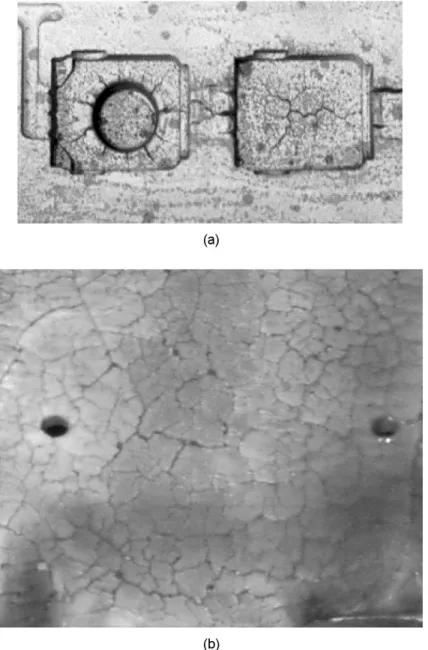
Industrial tools, such as forging matrixes, casting dies, glass molds, or hot rolling rolls, are well known to suffer from repeated transient thermal loading and to damage under thermal fatigue mode. This results in the appearance of cracks on the surface of the tools. Depending on the forming process, these cracks may be left free to propagate deep into the bulk of the tool. For instance, tools for the glass pressing industry are no longer used as soon as a few cracks longer than a few milli-meters appear on the surface. In the die casting industry, the tolerance of the process to crack development can be much larger and the die casters may wait until a biaxial network of cracks develops on a large scale of the surface. A network, as can be seen in Figure 1b, is called ‘‘heat checking.’’ Because forming processes are concerned
The authors are grateful to the French Technical Center for Foundry, the Fonderie Aluminium Cle´on and St. Gobain Pont a` Mousson for their financial support. The various studies performed with them helped us arrive at this theoretical analysis of thermal fatigue.
Address correspondence to G. Dour, CROMeP, Ecole des Mines d’Albi-Carmaux, Route de Teillet, Albi Cedex 9, 81 013, France. E-mail: [email protected]
with shaping a part, the shape of the dies are usually not simple and one often finds uniaxial crack networks such as that shown in Figure 1a. These cracks, usually asso-ciated with a geometrical singularity that acts as a stress riser, can be avoided or at least delayed by a smart modification of geometrical features, such as fillet radius. Optimization of the design can be performed with CAD software, based on the reduction of thermomechanical loading during the forming operation. Nevertheless, forming tools still heat-check in their flat areas. It has been observed, for instance, that high-pressure die casting (HPDC) dies tend to form heat checking next to the gates and in the thickest cavities even when perfectly flat. The heat checking in these areas proves to be just as limiting as the geometrical singularities.
The present paper is, therefore, concerned with the investigation of heat check-ing in those flat areas of industrial tools. Because cracks interfere with the processes
at an early stage of their development, the life of tools is not necessarily limited by a crack propagating deep into a tool. A few millimeters depth is usually sufficient to create a defect on an aesthetic product or to reduce drastically the productivity of a machine. The study of the initiation stage of heat checking is, therefore, of indus-trial relevance as well as of scientific interest.
To study the initiation stage of a crack network on a die, a laboratory test must be performed. Since the late 1950s, many thermal fatigue (TF) tests have been pro-posed. The geometry of the specimen and the type of heating have varied consider-ably from one author to another as follows: square specimen [1,2], wedged specimen [3!8], cylindrical specimen [9!16]; inductive heating [6,13!16], fluidized bed [4,10], dip into an aluminum melt [1,2] or flame [8,17].
The size of the specimen and the heating capacity vary greatly from one author to the other and are basically dictated by the available facilities. As a consequence, the results can differ from one test to another (e.g., the classifi-cation of materials is different among [1,2,15,16]). One of the major issues is the comparison of the results from one laboratory to another and, more important, the comparison with the industrial tools. Our analysis shows that the thermome-chanical loading is not comparable from one to another, and such a comparison has never been done. Indeed most of the papers on TF compare different mate-rials in given conditions instead of evaluating the effect of process parameters on the thermal fatigue.
The reasons why tools or TF specimens alter are linked to temperature and to thermomechanical loading that are imposed to their heated surfaces. Since the study of quenching-induced stresses [18] reported by Boley and Weiner [19], it has been well known that thermal stresses strongly depend on the thickness of the quenched parts: the thicker the parts, the larger the thermal stresses for the same heat transfer condition (same quenching medium). One can talk about a size effect: the same ther-mal loading will induce different therther-mal stresses on a thick industrial tool compared to a thin experimental specimen. As a consequence, it is necessary to take into account this scale effect to design TF lab specimens in order to reproduce the TF of an industrial tool. This is the main topic of the present paper.
In the following it will be considered that a flat tool (say, a slab) is accurately instrumented (e.g., see [20!22]) to know the temperature field T(z,t) as a function of time t and depth z. From this it is possible to evaluate the thermomechanical field of the tool r(z,t) ¼ rxx(z,t)¼ ryy(z,t), using either elastic body equations [19,23,24],
elastoplastic, or even elastoviscoplastic equations. To design a TF rig (e.g., specimen in Figure 2) that will become damaged in the same manner as the reference tool, the same loading has to be reproduced. The loading on the surface should be relevant enough in a TF study on the crack initiation and propagation. In this investigation, the attention is focused on crack initiation and propagation on the surface. However, the definition of the loading remains delicate. The thermomechanical loading con-sists of both the temperature and stresses (or strains) as functions of the time. As far as temperature is concerned, the replication criterion is simple; a relevant test should reproduce the same temperature history of the surface T(z¼ 0, t) of the tool to the surface of the specimen (e.g., T(/1, t) for the cylinder Figure 2). Where stresses
1. Which mechanical loading should be considered to simulate tool loading? 2. Simulate plastically relaxed stresses or the elastic body stresses?
3. Measure in terms of deformation, the total deformation, the elastic deformation, or the plastic deformation?
4. Or measure in terms of energy, the total loop energy, or the plastic loop energy? The choice is delicate considering that the damage criteria (stress, strain, energy, etc.) are not yet a generally accepted rule in TF. The origin of all the stresses and mech-anical strain is the incompatibility of thermal expansion when a part is heated or cooled with a nonuniform temperature. A lattice distortion of the crystal network is induced to accommodate the incompatibility of thermal expansion. The lattice dis-tortion comes together with the so-called thermal stresses of the elastic body. However, the elastic-body thermal stresses are often high enough to push disloca-tions to motion, inducing some plastic deformation. Evidently, this event is favored if the temperature is high. (Dislocation flow is a function of the temperature, applied stress, etc. [25].) As a consequence, the elastic-body thermal stresses and the tempera-ture taken together can be seen as the potential that measures the tendency of the material to deform plastically. In other words, they can be seen as the driving forces of the reaction of the material to the thermal loads, and to some extent of the damage of the tool.
As a consequence, the objective of a relevant TF rig design should be to repro-duce the same driving forces (temperature and elastic-body thermal stresses) applied to the surface of the reference tool, on the surface of the TF specimen. To account for the size effect between the thick reference tool and the small laboratory specimen, normalization of the heat conduction and elastic-body thermal stress equations are needed. A discussion about the size effect and time follows along with a method for dimensioning a TF experiment.
Figure 2. Scheme of a TF specimen in use in CROMeP [12]. (The inner diameter/ican be changed so that
NORMALIZED TRANSIENT THERMAL STRESSES IN SLAB
AND CYLINDRICAL GEOMETRY
To account for the scale effect of the reference tool (slab) and of the lab specimen (see Figure 2), a normalization transformation of the heat transfer and of the equa-tions for thermal stresses is a promising approach. General equaequa-tions are addressed for a slab geometry and then for a cylindrical geometry. Hereafter the (þ) indicates the normalized variables of the problem.
Normalized Thermal Stresses in a Slab
In a previous paper [23], the normalization of thermal stresses generated in a slab heated on one face and cooled down on the other face was proposed. The slab was considered an elastic body with constant physical properties and was free to buckle. The equations under concern were the heat conduction along the thickness z of the slab and the classical thermal stresses equation [19]. The heated face of the slab is subjected to a heat flux density /max during a time s, while the opposite
face is cooled down by a cooling fluid characterized by the heat transfer coefficient h and its average temperature Tfl (set to zero as the initial temperature of the slab for
the sake of simplicity). The normalization of the equations was made with the vari-ables /max, s and L, where L is half the thickness of the slab. Equations (1)!(6)
describe how the time, the depth into the slab, the heat flux density on the heated face, the heat transfer coefficient on the cooled face, the temperature, and the ther-mal stresses are transformed, respectively. It should be noticed that an equivalent temperature is used, based on the ratio (/maxL)=k:
tþ ¼ jt L2 ð1Þ zþ ¼ z L ð2Þ hþ ¼ hL k ð3Þ /þðtþÞ ¼//ðtÞ max ð4Þ Tþðzþ; tþÞ ¼Tðz; tÞ /maxL k ð5Þ rþðzþ; tþÞ ¼ Erðz; tÞa 1!m/max L k ð6Þ where j is the heat diffusivity of the slab, k is the heat conductivity of the slab, z denotes the ordinate along the thickness of the slab, L is half of the slab thickness,
h is the heat transfer coefficient at the back of the slab (cooled face), and/ and /max
denote heat flux density input at the front of the slab.
With that set of transformed variables, the thermal stresses expression reduces to a single equation, Eq. (7), in which the only parameter is the heat transfer coefficient hþ:
rþðzþ; tþÞ ¼ !Tþðzþ; tþÞ þ1 2 Z 2 0 Tþðzþ; tþÞ dzþ ! þ32ðzþþ 1Þ Z 2 0 ðz þþ 1ÞTþðzþ; tþÞ dzþ " ð7Þ
More details about the equations and illustration of the effect of hþ may be seen in the literature [23].
Normalized Thermal Stresses in a Cylindrical Geometry
The problem of thermal stresses in a cylinder is a classical plane-strain problem [19,24]. The heat conduction along the radius only is considered. The outer radius R2is subjected to a heat flux density /max during a time s. The inner radius R1 is
cooled down by contact with a cooling fluid characterized by the same couple h and Tfl (set to 0). The whole set of equations can be normalized with the same set
of transformations: Eqs. (1)!(6). The characteristic length L can be chosen as the minimum radius R1, the maximum radius R2, the thickness Ep¼ R2! R1, the
aver-age radius of the cylinder, and so on. In the following, the maximum radius R2will
be chosen to be the characteristic length, because our practice with the specimen in Figure 2 is to modify the inner radius and keep the outer radius constant. This allows us to work with the same heating equipment from one specimen to the other.
After normalization, the transient thermal stresses can be written as follows: rþrrðrþ; tþÞ ¼ ! 1 rþ2 1! Epþ ð Þ2!rþ2 1! Epþ ð Þ2!1 Z 1 1!Epþ rþTþðrþ; tþÞ drþ " þ Z rþ 1!Epþ rþTþðrþ; tþÞ drþ # ð8Þ rþ hhðrþ; tþÞ ¼ 1! Ep þ ð Þ2þrþ2 rþ2 Z 1 1!Epþ rþTþðrþ; tþÞ drþ þr1þ2 Z rþ 1!Epþ rþTþðrþ; tþÞ drþ ! Tþðrþ; tþÞ ð9Þ rþ zz ¼ m & ðrþrr þ rþhhÞ ! ð1 ! mÞ & Tþ ð10Þ
which stands for the plane-strain condition eþ
zz¼ 0, where Epþ ¼ Ep=R2 is the
Compared with the slab geometry, the normalized stresses depend on one more parameter: the thickness Epþ. Figure 3 shows the thermomechanical path rþ
hh and
rþ
zz vs. Tþ for the heated surface for cylinders with different Epþ and hþ.
A few facts are worth noting with regard to the curves in Figure 3.
i. For the short times (tþ< 0.04), the curves are all similar. Later, the evolution can follow three different tendencies:
Steady thermomechanical state: both the stress and the temperature reach a steady value, such as the (rþ
hh, Tþ) curves for the large hþ.
Steady stress but transient temperature: the stress reaches a steady value while the temperature keeps increasing; see the (rþ
hh, Tþ) curves for the small hþ.
In fact, the temperature field through the thickness of the cylinder stays the same but translates to higher temperatures, leading to a steady stress but not steady temperatures.
Transient temperature and stress; see the (rþ
zz, Tþ) curves.
ii. The maximum of stresses (in absolute value) occurs at the different normalized times for the different thicknesses. The reason is that the maximum stresses are attained when the heat wave reaches the inner radius of the specimen (R1), as
explained by Dour [23]. This time is roughly proportional to Ep2=j, or Epþ 2 in terms of normalized time.
iii. The stress at the surface of the cylinder is not, strictly speaking biaxial for the long time (tþ > 0.04) becauserþ
hh andrþzz are not equal. This is clearly seen in
Figure 3 when the temperature is high andrþ
hh reaches a steady value, whereas
rþ
zz keeps increasing. This is understandable when one considers the
plane-strain condition: the displacement in the z direction is zero, leading to stresses roughly equal to!EaT(R1) for the long times.
iv. There are two different regimes for the long times.
v. For large times (larger than 0.1), the stresses are strongly dependent on the heat transfer coefficient hþ, whereas for small times, the stresses are very similar. From a practical point of view, this means that TF tests in the long time range must be performed with an accurate control of the cooling conditions. This is not an easy task, because it depends on the type of fluid flow, the surface rough-ness, and, moreover, the limestone deposition in ‘‘hard water’’ countries. On the contrary, a TF test working in the short time range can be performed with a less-accurate cooling control. It is, therefore, advisable to work in the short time conditions, where the heat transfer coefficient has a negligible influence on the applied driving forces.
APPLICATION OF THE NORMALIZATION TO THE
DESIGN OF A TF TEST
Based on the normalized analysis of the first paragraph, two design examples are given. In the first, the geometry is kept the same (slab) and the design accounts for only the scale effect. The whole temperature and thermal stresses field replication
Figure 3. Thermal stresses history of the heated face of a cylinder. The dots corresponds to times incre-mented every 0.02 units of normalized time.
is discussed. The second example consists of replicating the temperature and the thermal stresses of the working face of the reference tool on the outer radius of the specimen (Figure 2).
From a Slab Tool to a Slab Specimen: Pure Scale Effect
In the following, the thickness of the reference slab is 2L and the thickness of the laboratory specimen is 2L0. The downscaling ratio is called A and is defined as
L¼ A&L0, where A is typically 10 to 100.
A perfect reproduction of both the temperature and the thermal stresses at the lab scale means obtaining stresses r0 and temperatures T0 at a location z0 in depth
and at the time t0 that satisfy the following:
r0ðz0 ¼ z=A; t0 ¼ tÞ ¼ rðz; tÞ
T0ðz0 ¼ z=A; t0 ¼ tÞ ¼ Tðz; tÞ
Considering Eqs. (1) and (2), it is clear that the perfect replica is not possible. If the factor A was applied to the thickness, the square root of A should be automatically applied to the time. The only way to obtain a perfect reproduction is to set A to 1. The best way to reproduce the temperature and the thermal stresses involves changing the duration of the test, or the frequency of the fatigue test. This is what will be called the ‘‘homothetic’’ replica. When the slab thickness is reduced by a fac-tor of A, the time is reduced by the facfac-tor A2. Reproducing stress and temperature is then relatively easy if the heat flux density/0
maxis A times/max. The thickness L and
the heat flux density are indeed multiplied in Eqs. (5) and (6). Table 1 summarizes the conditions of the homothetic downscaling.
Such a reduction may seem easy to perform; however, multiplying the heat flux density may become a technical issue when one faces industrial scale (see, for instance, HPDC [26!29]) with 1 to 50 MW=m2 during 100 ms. Applying 10 to 500 MW=m2for A¼ 10 during only 1!10 ms requires a huge and robust power sup-ply (even for a few square centimeter test rig). As an example, for a rig with a surface area of 17 cm2, a generator of 15!850 kW would be necessary. Moreover, it must be able to deliver its maximum power within a few milliseconds accurately. Technically speaking, this is not an easy task.
Table 1 Conditions for the homothetic replica of thermal stresses at a laboratory scale for a slab geomentry
Condition Industrial scale Laboratory scale Thickness, depth L, Z L0¼ L=A, z0¼ z=A
Heat flux density /max /max¼ A & /max
Time t t0¼ t=A2
Stress rðt; zÞ r0ðt0; z0Þ ¼ rðt; zÞ
From a Slab Tool to a Cylindrical Specimen
For practical reasons, it is often preferred to run a TF test on a cylindrical tube with induction heating. One of the reasons that hollow tubes are commonly used [14,30,31] is that the thickness is a parameter that influences the mechanical load. It is possible to adjust the mechanical loading without changing the temperature; it only requires changing the thickness. In our group we are now used to changing the inner radius of the specimen for a constant exterior radius (see Figure 2). Then none of the heating conditions have to be changed [12]. This is the reason we chose R2as the characteristic length in Eqs. (8)!(10). Inductive heating is used because it is
one of the most efficient ways to rapidly heat a metallic specimen on the scale of several square centimeters.
When the geometry is modified from the reference tool to the TF rig, it is obvi-ously impossible to replicate the entire temperature and thermal stress field. The rep-lication of the two driving forces has to be focused on the surface only. Nevertheless, the following equations show that it is possible to reproduce them at the same time, which prevents any frequency effect on the damage prediction when plastic fatigue condition prevails. In order to do so, the following method has been proposed:
i. Measure or collect information about the material’s key parameters (E, a, m, j, k).
ii. It is assumed that the working conditions of the reference tool have been determined. In particular, the maximum stresses rmax and maximum
tem-perature Tmax are recorded to occur at time s.
iii. From Eqs. (5) and (6), the following equation is obtained: Tþðrþ; tþÞ rþðrþ; tþÞ ¼ Tðr; tÞ rðr; tÞ Ea 1! m ð11Þ
This equation can be applied for r¼ R2 at the surface of the TF specimen
(i.e., rþ ¼ 1) and for time s (the same as identified on the reference tool) when the driving forces must be at their peak values. The nonnormalized stresses and temperature should then be Tmax and rmax as identified on the
reference tool: Tþ max rhh þmax ¼ Trmax max Ea 1! m ð12Þ
iv. Identify the ratio Tþmax=rhhþmax on the chart in Figure 4 (see the horizontal
line) using the second team of Eq. (12) with the maximum temperature, maximum stresses, and the materials data.
v. At that point it is necessary to choose the normalized thickness Epþ of the tube and the relative heat transfer coefficient hþ. This means choosing one of the curves. Where the chosen curve crosses the horizontal line (when it does), the time sþ reads as the normalized time that should be used on the lab specimen to reproduce the real time s on the industrial tool.
Figure 4. Chart of the ratio Tþ=rþvs. tþ involving (a) the hoop stressr
hhand (b) the axial stressrzzfor a
vi. To obtain the same time on the lab specimen as on the actual part, the ref-erence length R2must satisfy Eq. (1), which leads to Eq. (13):
R2 ¼ ffiffiffiffiffi js sþ r ð13Þ vii. From the chart found in Figure 3, it is now possible to determine Tþmaxand
rhhþmax at the instantsþ.
viii. The heat flux density that is needed to perform such a TF test is given by Eq. (14) and the power supply that is needed for a tube of length Z is given by Eq. (15): /max ¼ Tmax Tþ max k R2 or /max ¼ rmax rþ max 1! m Ea k L ð14Þ P¼ 2pR2Z/max ð15Þ
From the chart in Figure 4, one may arrive at the following conclusions.
i. When the inner radius is thermally insulated (hþ is small), the absolute ratios for the ortho-radial stress component continue to increase during heating. This is understandable, because Figure 3 shows that thermal stress rþhh tends to a steady value while the temperature keeps increasing. The trend is differ-ent for the ratio with the axial stress compondiffer-ent, because the thermal stress tends to increase proportionally to the temperature.
ii. When hþ is large, the curves Tþ=rþ reach a steady value, because both stress and temperature tend to finite values. This applies for both axial and hoop stress components, but the limit values are not the same.
iii. The slopes at the origin are different if the thicknesses are different. This con-firms that, in nonperfect contact condition, the size influences the thermal stresses.
iv. When the heat transfer coefficient hþ is small, the absolute ratio is a decreas-ing function of the thickness Epþ. The contrary applies when the heat trans-fer coefficient is large, at least for long times. This means that a classification of the TF results as a function of thickness can be changed whether the cylinder works in high or low internal heat transfer conditions and for long or short times. The reason for this reverse order can be understood in that, in high internal heat transfer, the global temperature gradient through the thickness is forced by hþ. In this condition, the thicker the tube, the lower the gradient and the smaller the stresses. On the contrary, when the transfer coefficient is small, the global temperature gradient is controlled by the ther-mal inertia of the tube. Thus, the thicker the tube, the larger the gradient and then the larger the thermal stresses.
v. The absolute ratio is always larger than 1. The value 1 appears as a limit value that can be obtained only for extremely short times, whatever the thick-ness of the tube. This fact corresponds to the limit case of no penetration of the heat wave, such as in the beginning of the perfect contact condition. It
follows from this that it will be impossible to set a stress larger than that of Eq. (16) at a given time. To achieve such a stress, an infinitely large heat flux density is required and the targeted temperature T would be reached in an extremely short time. This corresponds to the situation described by the fect contact between a part whose initial temperature is set to 0 and a per-fectly stirred fluid at temperature T, as described by Boley and Weiner [19]. If fact, the inverse of the absolute ratio appears to be a measure of the intensity of the thermal shock:
rhh;lim ¼ rzz;lim ¼ !
Ea
1! mT ð16Þ
In conclusion, the cylindrical geometry will not be able to create stresses higher than the perfect contact thermal stresses. Therefore, thermal stresses due to geometrical singularities, where stress concentration factors apply, cannot be handled by such a test.
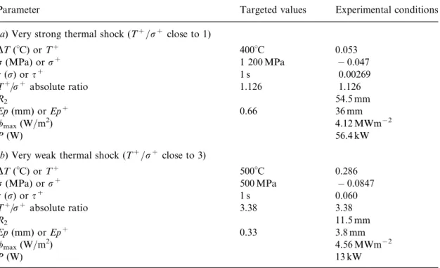
Table 2 presents results inspired from some examples that have been studied in the CROMeP research center. The lab specimen is 40 mm long. The material is the AISI H11 steel, whose physical properties are E=(1! m) ¼ 260 GPa and a ¼ 1.3 ' 10!5 K!1 and thermal properties are k¼ 30 Wm!1K!1 and j ¼ 8 ' 10!6m2s!1 [12].
Table 2 Examples of TF designs
Parameter Targeted values Experimental conditions (a) Very strong thermal shock (Tþ=rþ close to 1)
DT ((C) or Tþ 400(C 0.053 r (MPa) or rþ 1 200 MPa ! 0.047 s (r) or sþ 1 s 0.00269 Tþ=rþ absolute ratio 1.126 1.126 R2 54.5 mm Ep (mm) or Epþ 0.66 36 mm /max(W=m2) 4.12 MWm!2 P (W) 56.4 kW
(b) Very weak thermal shock (Tþ=rþ close to 3)
DT ((C) or Tþ 500(C 0.286 r (MPa) or rþ 500 MPa ! 0.0847 s (r) or sþ 1 s 0.060 Tþ=rþ absolute ratio 3.38 3.38 R2 11.5 mm Ep (mm) or Epþ 0.33 3.8 mm /max(W=m2) 4.56 MWm!2 P (W) 13 kW
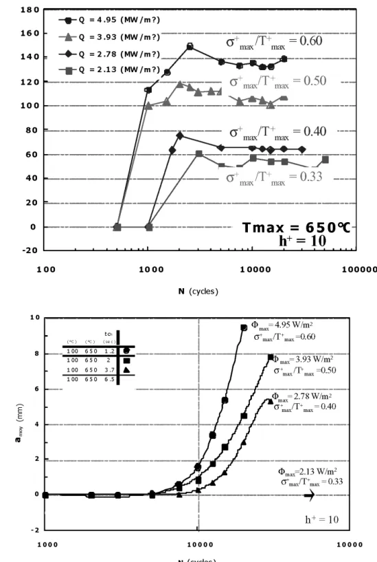
Figure 5. Evolution of microheat checking density and of macrocrack propagation on the surface of a specimen for different repeated thermal chocks.
CONCLUSIONS
We propose that a transient TF test should be designed to respect the same temperature and elastic body thermal stresses, so-called ‘‘driving forces’’ of the damaging process, as in a real tool. Most of the time it is impossible to reproduce a homothetic temperature and stress field in the laboratory specimen. However, as far as one intends to study the heat-checking initiation on the surface of the compo-nent, reproducing the driving forces on the surface of a hollow tube is sufficient and relevant.
We explain an original and rapid method to design a TF lab test based on the normalization of heat transfer and thermal stresses equations for a cylindrical geometry. This method requires that the designers know what set of driving forces they are seeking. Prior to any TF design attempt, measurement and simulation of the working condition of the real tool must be performed. From this point, using a chart and a limited amount of calculations, it is possible to design the whole geometry (inner radius, thickness) and the heating conditions (power supply, heating duration). It appears that, for a given set of driving forces to be reproduced, there is only one solution to the problem, provided that the thermal boundary condition hþand the Ep=R2 ratio are previously chosen.
The ratio that is used in Figure 4 and Eq. (12) provides a way to rank the ther-mal shocks. The larger the absolute value of the ratio, the lower the therther-mal shock. The largest thermal shock that can be attained is given by the well-known Eq. (16). We propose to call the inverse ratio, jrþmax=Tmaxþ j, the intensity of a thermal shock.
The present method has been used recently on TF rigs such as that described in Figure 2. The parameterrmaxwas changed at constant Tmaxsimply by modifying the
heating durations and the maximum heating capacity Umaxwith the same thickness
of specimen. Different types of damage, such as the density of microcracks (or heat checking in the oxide scale) and the macrocrack propagation on the surface of the specimen, are shown in Figure 5 [32]. It is worth observing that the two criteria for the damage of the specimen are strongly dependent on the intensity of the ther-mal shock jrþ
max=Tmaxþ j.
REFERENCES
1. J. C. Benedyck, D. J. Moracz, and J. F. Wallace, Thermal Fatigue Behavior of Die Materials for Alu-minium Die Casting, Proceedings of 6th SDCE International Die Casting Congress, North American Die Casting Association Publ., paper 111, 1970.
2. R. R. Graham and J. F. Wallace, Thermal Processing Structure and Thermal Fatigue Relation for Die Steel, DCRF Technical Bulletin 01-74-05D, CWRU, 1974.
3. C. C. Engler-Pinto, Etude de l’endommagement en fatigue thermo-me´canique de superalliages a` base de nickel, Thesis, Ecole Polytechnique Fe´de´rale de Lausanne, Lausanne, France, 1996.
4. E. Glenny, A Technique for Thermal-Shock and Thermal Fatigue Testing Based on the Use of Flui-dized Solids, J. Inst. Met., vol. 84, p. 294, 1958.
5. E. Glenny, Thermal and high strain fatigue, The Institute of Metals, pp. 346!363, 1967.
6. F. Meyer-Olbersleben, C. C. Engler-Pinto, Jr., and F. Rezaı¨ Aria. On Thermal Fatigue of Nickel-Based Superalloys, in Thermo-mechanical Fatigue Behavior of Materials, ASTM 1263, American Society for Testing and Materials, pp. 41!55, 1996.
7. F. Rezaı¨ Aria, M. Francois, and L. Remy, Thermal Fatigue of MAR-M509 Superalloy. I) The Influ-ence of Specimen Geometry on the Thermal Fatigue Behaviour, Fatigue Fract. Eng. Mater., vol. 11, pp. 277!289, 1988.
8. F. Rezaı¨ Aria, B. Dambrine, and L. Remy, Thermal Fatigue Behaviour of MAR M509 Superalloy, II) Evolution of Life Prediction Models, Fatigue Fract. Eng. Mater., vol. 11, pp. 291!302, 1988. 9. M. A. H. Howes, Heat Checking in Die Casting Dies, Die Cast. Eng., March!April, pp. 12!16, 1969. 10. M. A. H. Howes, Evaluation of Thermal Fatigue Resistance of Metals Using the Fluidized Bed Technique, Proc. Fatigue at Elevated Temperatures, ASTM STP 520, American Society for Testing and Materials, pp. 242!253, 1973.
11. M. A. H. Howes, A Study of Thermal Fatigue Mechanisms, Proc. Thermal Fatigue of Materials and Components, American Society for Testing and Materials, pp. 87!105, 1976.
12. S. Jean, Me´thodologie d’exploitation me´canique et microstructurale d’un essai de fatigue thermique: Application a` l’e´tude du faı¨enc¸age d’un acier pour outil de forge a` chaud, Thesis, Universite´ Paul Sabatier, Toulouse, France, 1999.
13. S. Jean, B. Miquel, S. Leroux, and F. Rezaı¨!Aria, An Investigation on Heat Checking of Hot Work Tool Steels, Proc. 5th International Tooling Conference, 1999.
14. D. Rousseau, J. P. Riegert, L. Seraphin, and R. Tricot, Fatigue thermique des aciers a` outils pour travail a` chaud, Proc. Colloque pour les Aciers a` Outils pour Travail a` chaud, SF2M Publ., pp. 293!320, 1977. 15. V. Ahuja and M. Z. Jahedi, Alternative Die Materials—A Comparison of Four Hot Work Tool Steels for Use in High Pressure Die Casting Dies, Proc. IMEA Conference (Eds. E. V. Pereloma and G. H. Edward), pp. 23!28, 1999.
16. V. Ahuja and M. Z. Jahedi, Heat Checking—A Comparison of Five Hot Work Tool Steels for Use in High Pressure Die Casting Dies, Proc. 21st International Die Casting Congress & Exhibition, North American Die Casting Association, paper T01!103, p. 337, 2001.
17. T. Suzuki, M. Ishihara, and H. Miyachi, Residual Stress and Heat Checking in Die Casting Dies, Transaction of the 7th SDCE International Die Casting Congress, paper 6472, 1972.
18. H. G. Landau and V. Paschkis, Charts on Elastic Thermal Stresses in Heating and Cooling of Slabs and Cylinders, ASME, paper A238, 1957.
19. B. A. Boley and J. H. Weiner, Theory of Thermal Stresses, Krieger Ed., Malabar, Florida, 1985. 20. S. Broucaret, A. Michrafy, and G. Dour, Heat Transfer and Thermo-mechanical Stresses in a Gravity
Die—Influence of Process Parameters, J. Mater. Process. Technol., vol. 110, pp. 211!217, 2001. 21. G. Dour, M. Dargusch, and C. Davidson, Non Intrusive Heat Transfer Coefficient Gauge for
Alu-minium High Pressure Die Casting, Report, CAST for Metals Manufacturing, Brisbane, 2002. 22. G. Dour, M. Dargusch, and C. Davidson, Developments Relating to Measurements of Temperatures
and Heat Transfer Coefficients, Australian, patent application 20029553328, 2002.
23. G. Dour, Thermal Stresses and Distortion in Dies of Die Casting Processes—A New Normalised Approach, Modell. Simul. Mater. Sci., vol. 9, pp. 399!413, 2001.
24. S. Timoshenko and S. Winowsky, Theory of Elasticity, 3rd ed., McGraw!Hill Int. Ed., Singapore, 1970. 25. Y. Estrin and H. Mecking, A Unified Phenomenological Description of Work Hardening and Creep
Based on One-Parameter Models, Acta Metall., vol. 32, pp. 57!70, 1984.
26. V. Davies, Heat Transfer in Gravity Die Castings, Brit. Foundryman, vol. 73, pp. 331!334, 1980. 27. S. Hong, D. G. Backman, and R. Mehrabian, Heat Transfer Coefficient in Aluminium Alloy Die
Casting, Metall. Trans. B, vol. 10, pp. 299!301, 1979.
28. P. Schmidt, Heat Transfer in Permanent Mould Casting, Thesis, Royal Institute of Technology, Stockholm, 1994.
29. V. Venkatasamy, J. Brevick, C. Mobley, and G. Pribyl, NADCA Sponsored Research: Die Cavity sen-sors for Monitoring Die Casting Processes, Proc. World of Die Casting, North American Die Casting Association, pp. 151!154, 1997.
30. S. Malm, M. Svensson, and J. Tidlung, Heat Checking in Hot Work Steels, 2nd Colloque International Les Aciers a` Outils pour travail a` chaud, SF2M Publ., 1977.
31. M. Seux, S. Ignan, and R. Leveque, Improvement Service Life for MPM H13 Mendrels, Proc. Mech-anical Working and Steel Processing Conference, pp. 47!55, 1988.
32. F. Medjedoub, S. Leroux, G. Dour, F. Rezaı¨!Aria, P. Hairy, K. Khang!Ny, and M. Golin, An investigation on Thermal Fatigue Surface Cracking of 5CrMoV Die Tool Steels, Proc. of NADCA Conference, North American Die Casting Association, T03-056, 2003.
![Figure 2. Scheme of a TF specimen in use in CROMeP [12]. (The inner diameter / i can be changed so that the wall thickness Ep varies from 5, 7, and up to 10 mm.)](https://thumb-eu.123doks.com/thumbv2/123doknet/12268804.321446/5.892.162.587.144.454/figure-scheme-specimen-cromep-diameter-changed-thickness-varies.webp)