DESIGN AND ANALYSIS OF SLOT BASED TRANSPARENT MAGNET-LESS NON-RECIPROCAL METASURFACES
BURAK GURLEK
DÉPARTEMENT DE GÉNIE ÉLECTRIQUE ÉCOLE POLYTECHNIQUE DE MONTRÉAL
MÉMOIRE PRÉSENTÉ EN VUE DE L’OBTENTION DU DIPLÔME DE MAÎTRISE ÈS SCIENCES APPLIQUÉES
(GÉNIE ÉLECTRIQUE) AOÛT 2015
ÉCOLE POLYTECHNIQUE DE MONTRÉAL
Ce mémoire intitulé :
DESIGN AND ANALYSIS OF SLOT BASED TRANSPARENT MAGNET-LESS NON-RECIPROCAL METASURFACES
présenté par : GURLEK Burak
en vue de l’obtention du diplôme de : Maîtrise ès sciences appliquées a été dûment accepté par le jury d’examen constitué de :
M. AKYEL Cevdet, D. Sc. A, président
M. CALOZ Christophe, Ph. D., membre et directeur de recherche M. SIROIS Frédéric, Ph. D., membre
DEDICATION
As the conclusion of my M.Sc study, I want to take this chance to sincerely thank many people for their endless support. I’m very grateful to my advisor, Prof. Christophe Caloz, for his generous acceptance of me as a member of his research group, and I want to thank him for his guidance, support and patience during my study. I learnt a lot of valuable lessons beyond just science from the fruitful research environment provided by him. I was very lucky to be a part of one of the strongest research group in electromagnetic theory.
I would also like to thank all my committee members : Prof. Cevdet Akyel and Prof. Frédéric Sirois for their time and efforts in reviewing my thesis and their attendance to my thesis defense. I want to thank Dr. Salem, Dr. Sounas and Dr. Kodera for their support, encouragement and friendship. My gratitude is extended to Mrs. Desparois and Mrs. Pavlov for their administrative work and to Mr. Décarie for his IT support.
I want to thank all my friends : Mohamed Salem, Amar Al-Bassam, Seyyid M. Dilek, Levent Erdogan, Karim Achouri, Hualin Zhan, Babak Nikfal, Nima Chamanara and Yangping Zhao. Thank you for being my friends, I have remembered and I appreciate every single favor that I have received from any of you during this path.
Last but not least, I would like to thank my parents, who gave me the birth and brought me up. They always support me. I would like to express my deepest gratitude to my source of happiness Ayca Onur, for her endless love, encouragement and support.
RÉSUMÉ
Le but de ce travail de recherche est de concevoir et d’analyser des métasurfaces gyrotro-piques non-réciproques ne nécessitant pas de champ de polarisation magnétique. Une réponse non-réciproque peut être obtenue en brisant la symétrie par renversement du temps (symétrie T). Ce qui peut être réalisé en utilisant des quantités qui sont antisymétriques par renverse-ment du temps comme le champ magnétique, le courant électrique, le morenverse-ment et le morenverse-ment angulaire orbital. Dans ce travail, un courant électrique de polarisation est utilisé pour briser la symétrie T et ainsi obtenir une réponse gyrotropique non-réciproque.
Un réseau périodique en deux dimensions constitué d’ouvertures annulaires terminées par de grandes ouvertures carrées et chargées par des semi-conducteurs unidirectionnels est sug-géré pour réaliser une métasurface non-réciproque sans polarisation magnétique (MNM). Il est montré qu’une terminaison avec de larges ouvertures carrées est nécessaire pour assurer une adaptation d’impédance entre les ouvertures annulaires et les composants unidirectionnels. De ce fait, une structure MNM est conçue pour obtenir une résonance à ondes progressives, i.e. un dipôle magnétique tournant se comportant de la même façon qu’une molécule de fer-rite magnétisée. Les coefficients de réflexion et de transmission de la structure sont calculés numériquement pour en démontrer la réponse gyrotropique non-réciproque. Par ailleurs, la réponse asymétrique de la structure, pour des ondes planes incidentes de polarisation en x ou en y, est mise en évidence et il est suggéré qu’une rotation de la structure permettrait une réponse symétrique non-réciproque au prix de perdre l’effet gyrotropique non-réciproque similaire aux structures en ferrite.
Une explication physique de l’effet gyrotropique non-réciproque, obtenu en empêchant la propagation dans le sens inverse de l’un des modes-propres de la structure, est fournie en utilisant la théorie de Sturm-Liouville. Afin de comprendre la réponse électromagnétique d’une métasurface, les paramètres bi-anisotropiques de surface sont analytiquement dérivés en fonction des dyades de réflexion et de transmission basées sur les conditions aux limites. Les paramètres bi-anisotropiques de surface de la structure MNM sont extraits des résultats de simulations numériques. La réponse magnétique dipolaire de la structure MNM apparaît de manière évidente à travers ses paramètres d’impédance de surface. Etant donné que les paramètres d’impédance de surface sont bien plus élevés comparés aux autres paramètres bi-anisotropiques de surface, un simple modèle de ligne de transmission est proposé pour mo-déliser la structure MNM monocouche. Malgré le fait que le comportement non-réciproque similaire à la ferrite peut être atteint avec une structure MNM, celle-ci possède un coefficient de réflexion important dû à sa taille plus petite que la longueur d’onde. Afin de contourner le
sont discutées et une analyse préliminaire est employée. Premièrement, le théorème de dua-lité est exploité pour annuler la réflexion de la structure MNM étant donné que la structure conçue peut être caractérisée par un moment magnétique dipolaire. Les conditions pour an-nuler la réflexion, appelées les conditions de Kerker, sont dérivées et montrent qu’un moment électrique dipolaire tournant est requis pour annuler la réflexion de la structure MNM. Etant donné qu’un moment électrique dipolaire tournant n’a jamais été réalisé à ce jour, une se-conde méthode basée sur des résonances de Fabry-Pérot a été envisagée. Afin de réaliser une cavité de Fabry-Pérot, deux surfaces monocouches de type MNM sont mises l’une à la suite de l’autre avec un substrat diélectrique d’épaisseur d les séparant. Un modèle de ligne de trans-mission, qui est basé sur le modèle pour une seule couche MNM, est utilisé pour calculer de manière analytique les dyades de réflexion de la structure MNM à deux couches. L’épaisseur du substrat diélectrique, permettant d’annuler la réflexion, est alors analytiquement obtenue. Deux exemples de systèmes sont proposés. Dans le premier exemple, deux ouvertures annu-laires chargées avec un composant unidirectionnel parfaitement adapté en impédance sont utilisés pour concevoir la cavité de Fabry-Pérot. Il est démontré que l’épaisseur du diélectrique requise pour annuler la réflexion est imaginaire à cause des pertes inhérentes de la structure. Il est également montré que les pertes de la structure sont causées par le fait que l’on empêche la propagation en sens inverse d’un des modes-propres rendant ainsi impossible une parfaite annulation de la réflexion en utilisant le principe de cavité de Fabry-Pérot. Les coefficients de réflexion et de transmission de la structure MNM à deux couches sont calculés de manière semi-analytique en utilisant le modèle décrit ci-dessus ainsi que les paramètres d’impédance de surface obtenus par simulation. Il est déterminé que cette structure MNM à deux couches possède également une réflexion non négligeable. De ce fait, un compromis existe entre les pertes inhérentes de la structure monocouche et son coefficient de transmission. Dans le se-cond exemple, deux ouvertures annulaires chargées avec un composant unidirectionnel qui n’est pas adapté en impédance sont utilisés pour concevoir la cavité de Fabry-Pérot. Etant donné que les pertes de la structure sont réduites du fait de la différence d’impédance, le coefficient de transmission de la structure est nettement amélioré et une importante réponse gyrotropique est obtenue. Cependant, à cause de la non-minimisation du coefficient de ré-flexion, la résonance à ondes progressives est détériorée menant à un plus faible facteur de non-réciprocité.
Etant donné que la réponse non-réciproque de la structure MNM à deux couches est faible, une méthode est introduite pour contrôler l’effet gyrotropique et la non-réciprocité de cette structure. Il est montré que la réponse non-réciproque et gyrotropique de la structure MNM mono couche peut être contrôlée en ajoutant un délai de phase au composant
unidirection-nel ainsi qu’en effectuant une rotation de la cellule unitaire. La méthode proposée est basée sur une technique d’optimisation de contraintes non-linéaires dont la fonction de coût est minimisée selon les dyades de réflexion et de transmission désirées de la structure MNM à deux couches. Ainsi, les dyades d’impédance de la surface mono couche qui minimisent la fonction de coût peuvent être déterminées. Finalement, la structure MNM mono couche est synthétisée grâce au délai de phase du composant unidirectionnel et de l’angle de rotation de la cellule unitaire. Un exemple de conception est proposé comme preuve de concept et consistant en une métasurface transformant une onde plane polarisée en y et normalement incidente en une onde plane polarisée en x tout en reflétant toutes les autres et présentant un important facteur de non-réciprocité. A cause de la largeur de bande limitée de cette structure, une vérification expérimentale n’a pas pu être menée.
The goal of this research is to design and analysis of transparent magnet-less non-reciprocal gyrotropic metasurfaces (MNMs). Non-reciprocal response requires breaking of the time-reversal symmetry and could be realized with quantities that are odd vector under time reversal such as magnetic field, current, momentum and orbital angular momentum. Current biasing is used to break the time-reversal symmetry and to achieve transparent non-reciprocal gyrotropic response.
A 2D periodic array of annular slotted ring structure terminated with big slot patches and loaded with semiconductor-based unidirectional components is suggested to realize a transparent magnet-less non-reciprocal gyrotropy. It is shown that the big slot termina-tion is required for matching of the annular slotted transmission line and the unidirectermina-tional component. Thus, a slot MNM is designed to achieve a travelling wave resonance, i.e. the rotating magnetic dipole response as magnetized ferrite molecules. Reflection and transmis-sion coefficients of the designed structure are numerically computed to prove the ferrite-like non-reciprocal gyrotropic response of the structure. Moreover, asymmetrical response of the structure under x- and y-polarized plane wave incidence is highlighted and a rotated design is suggested to have a symmetrical non-reciprocal response in the expense of destroying the ferrite-like non-reciprocal gyrotropy.
A physical explanation of the non-reciprocal gyrotropy, achieved by prohibiting one of the counter-propagating eigenstates of the slot MNM, is provided by utilizing the Sturm-Liouville theory. In order to understand the electromagnetic response of a metasurface, bianisotropic surface parameters of the metasurface is analytically derived in terms of reflec-tion and transmission dyadics from discontinuity of the electromagnetic fields. Bianisotropic surface parameters of the slot MNM is extracted from the numerical simulation results. Mag-netic dipole moment response of the slot MNM is evident from its large surface impedance parameters. Since surface impedance parameters of the structure is very large compared to other bianisotropic surface parameters, a simple transmission-line model is suggested to model the single-layer slot MNMs. Although ferrite-like transparent non-reciprocal behaviour could be achieved with slot MNMs, there is a non-negligible reflection from the structure due to its subwavelength nature.
In order to circumvent the reflection issue of slot MNMs, reflection cancellation methods are discussed and a tentative analysis is employed. First, the duality theorem is exploited to cancel the reflection of slot MNMs since the designed structure could be characterized with a magnetic dipole moment. The reflection cancellation conditions, namely Kerker
con-ditions, are derived where a rotating electric dipole moment response is required to cancel the reflection of slot MNMs. Since the rotating electric dipole moment response has not been realized so far, the second method based on Farby-Pérot resonances is introduced. In order to form a Farby-Pérot cavity, two single-layer slot MNMs are cascaded with a dielec-tric spacer with thickness d. The network model for the double layer slot MNMs based on transmission-line model of the single-layer slot MNM is used to analytically calculate the reflection dyadic of the double layer structure. The thickness of the dielectric spacer which makes the reflection dyadic zero is analytically derived. Two design examples are provided. In the first example, two annular slotted rings loaded with perfectly matched unidirectional components are utilized to design Farby-Pérot cavity. It is shown that the dielectric spacer thickness required to cancel the reflection dyadic is imaginary due to the inherent loss of the structure. It is shown that inherent loss of the structure is caused by prohibiting one of the counter-propagating eigenstates so that the perfect reflection cancellation cannot be achieved with Farby-Pérot cavities. Reflection and transmission coefficients of the double layer slot MNMs are semi-analytically calculated by using the introduced network model and the extracted surface impedance parameters. It is shown that the double layer structure has non-negligible reflections. Thus, the trade-off between inherent loss of the single-layer slot MNM and its transparency is highlighted. Thus, a new design based on low level of inherent loss is suggested to increase the transparency. In the second design, two annular slotted rings loaded with imperfectly matched unidirectional components are utilized to design the Farby-Pérot cavity. Since the inherent loss of the structure is degraded with the imperfect matching, the transparency of the double layer slot MNM is greatly increased and strong gyrotropic response is achieved. However in the expense of reflection minimization, the trav-elling wave resonance is destroyed so that the non-reciprocal response is reduced.
Since non-reciprocal response of the highly transparent double layer slot MNMs are weak, a method is introduced to control the gyrotropy and non-reciprocity with the double layer slot MNMs. It is shown that non-reciprocal and gyrotropic response of the single-layer slot MNMs can be controlled with phase shift of the unidirectional component and rotation an-gle of the unit-cell. The proposed method is based on a non-linear constraint optimization technique where the cost function is minimized according to the desired reflection and trans-mission dyadics of the double layer slot MNM. The required single-layer surface impedance dyadics that minimizes the cost function are found. Lastly, the single-layer slot MNMs are synthesized based on phase shift of the unidirectional component and the rotation angle of the unit-cell. A design example is provided as a proof-of-concept where the designed metasurface transform y-polarized normally incident propagating plane waves into x-polarized ones while reflecting the others and has a huge non-reciprocal response.
DEDICATION . . . iii
ACKNOWLEDGEMENTS . . . iv
RÉSUMÉ . . . v
ABSTRACT . . . viii
TABLE OF CONTENTS . . . x
LIST OF TABLES . . . xii
LIST OF FIGURES . . . xiii
LIST OF SYMBOLS AND ABBREVIATIONS . . . xix
LIST OF APPENDIXES . . . xxii
CHAPTER 1 INTRODUCTION . . . 1
1.1 Definitions and Basic Concepts . . . 1
1.2 Research Objectives . . . 4
1.3 Thesis Plan . . . 5
CHAPTER 2 GYROTROPY, NON-RECIPROCITY AND MNM TECHNOLOGY 6 2.1 Gyrotropy and Non-Reciprocity . . . 6
2.1.1 Microscopic and Macroscopic Properties of Ferrimagnetic Materials . 7 2.2 MNMs Technology . . . 11
2.2.1 MNMs Based on Current Biasing . . . 13
CHAPTER 3 SINGLE-LAYER SLOT TYPE TRANSPARENT MNMs . . . 15
3.1 Transparent MNMs Design . . . 15
3.2 Physical Explanation of the Non-Reciprocity of Transparent Slot MNMs . . 33
3.3 Characterization of The Transparent Slot MNMs . . . 36
3.3.1 Full Surface Parameter Extraction of the Slot MNM . . . 36
CHAPTER 4 MULTI-LAYER SLOT MNMs STRUCTURE FOR MINIMAL
REFLEC-TION . . . 44
4.1 Reflection Minimization for Non-reciprocal Gyrotropic materials . . . 44
4.2 Reflection Cancellation Methods . . . 45
4.2.1 Exploiting the Duality Theorem . . . 45
4.2.2 Exploiting Farby-Pérot Resonances . . . 47
4.3 Network Model for double-layer Slot MNM Structures . . . 48
4.4 Design Example : Highly Transparent Non-reciprocity via double-layer Slot MNM . . . 51
4.5 Controlling Gyrotropy and Non-reciprocity by using Multi-layer Slot MNMs 64 4.5.1 Design Example : Controlling the Gyrotropy and Non-reciprocity by Using double-layer Slot MNM Structures . . . 68
CHAPTER 5 CONCLUSION . . . 72
REFERENCES . . . 75
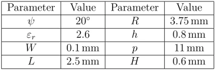
Table 3.1 Design parameters of the slot MNM resonating at 5.3 GHz. . . . 20 Table 4.1 Design parameters of the slot MNM resonating at 8.4 GHz. . . . 57
LIST OF FIGURES
Figure 1.1 (a) Illustration of atomic structure of a natural material. (b) Illustra-tion of a metamaterial with its subwavelength artificial atoms [1]. . . 2 Figure 2.1 Electromagnetic response of a gyrotropic media [2]. . . 6 Figure 2.2 (a) Illustration of a reciprocal gyrotropy. (b) Illustration of a
non-reciprocal gyrotropy (time-reversal case) [2]. . . 8 Figure 2.3 Illustration of a spinning electron around the direction of biasing static
magnetic field [3]. . . 9 Figure 2.4 (a) Illustration of interaction of the RCP plane wave with a
magne-tized ferrite electron biased with +ez directed biasing magnetic field. (b) Illustration of interaction of the LCP plane wave with magnetized ferrite electron biased with +ez directed biasing magnetic field [3]. . . 10 Figure 2.5 (a) Band structure of spatiotemporally modulated silicon waveguide [4].
(b) Illustration of I-MNMs based on current biasing and electron spin of magnetized ferrites [5]. (c) Illustration of L-MNMs based on azimuthal spatiotemporal modulation of the refraction index along conductive ring pair structure and its counter-propagating eigenstates [6]. . . 12 Figure 2.6 (a) Illustration of even mode operation of the microstrip I-MNM. (b)
Illus-tration of odd mode operation of the microstrip I-MNM. (c) IllusIllus-tration of the induced magnetic dipole moment by odd mode of the microstrip I-MNM [7]. (d) Fabricated microstrip I-MNM, top and bottom of the substrate [8]. . . 13 Figure 3.1 (a) Slot MNM design based on the Babinet principle. (b) The
trans-mission line model of the designed Slot MNM with electrical length
βℓ. . . 16
Figure 3.2 (a) Modified slot MNM design based on the Babinet principle. (b) An-nular slotted ring structure with its design parameters. (c) Transmission line model of the modified slot MNM. . . 17 Figure 3.3 (a) Characteristic impedance of a slot transmission line for different
slot widths. (b) Effective permittivity of a slot transmission line for different slot widths. Thickness of the substrate is 0.8 mm, relative permittivity of the substrate is 2.6. . . . 17
slotted ring structure. (b) Cross section view of magnetic field distri-bution of the modified annular slotted ring structure. . . 19 Figure 3.5 Transverse current and field distribution of the designed slot MNM
at different time instances. (a) t = t0. (b) t = t0 + T/4. (c) t = t0 +
T /2. (d) t = t0+ 3T/4 where T is period of the incident plane wave. . 20
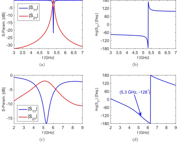
Figure 3.6 S-parameters of the ports A and B, shown in Fig. 3.2(c). (a) Magni-tude of S11 and S21 computed by ADS. (b) Phase of S21 computed by ADS. (c) Magnitude of S11 and S21 computed by HFSS (d) Phase of
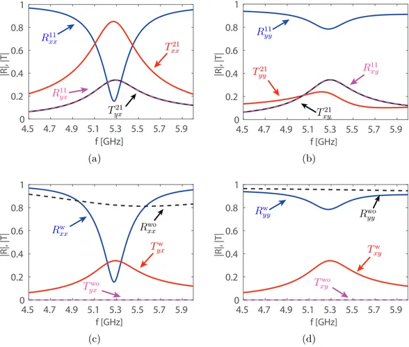
S21 computed by HFSS. . . 22 Figure 3.7 Reflection and transmission coefficients of the designed slot MNM
ba-sed on the parameters given in Table 3.1 under plane wave illumination from z > 0.(a) x-polarized plane wave incidence. (b) y-polarized plane wave incidence. The comparison of reflection and transmission coef-ficients of the unidirectional component loaded (w superscript) and the unloaded structure (wo superscript) under plane wave illumina-tion. (c) x-polarized plane wave incidence. (d) y-polarized plane wave incidence. . . 24 Figure 3.8 Non-reciprocity of the designed slot MNM : Comparison of the
trans-mission coefficients when the structure is excited from z > 0 and z < 0 in time-reversal schema. (a) Magnitude. (b) Phase. . . 25 Figure 3.9 Time evaluation of the transverse electric current along unit-cell of
the slot MNM computed by using HFSS and Ansoft Designer. (a) t =
t0. (b) t = t0+ T/8. (c) t = t0+ T/4. (d) t = t0+ 3T/8. . . . 26 Figure 3.10 Time evaluation of the magnetic fields transverse to ez direction along
unit-cell of the slot MNM computed by using HFSS and Ansoft Desi-gner. (a) t = t0. (b) t = t0+ T/8. (c) t = t0+ T/4. (d) t = t0+ 3T/8. . 27 Figure 3.11 (a) Ellipticity of the designed slot MNM. (b) Faraday rotation angle of
the designed slot MNM. . . 29 Figure 3.12 (a) Transmission coefficients of the slot MNM under the RCP and the
LCP plane wave illumination from z > 0. (b) An ideal symmetric slot MNM. . . 29
Figure 3.13 (a) Reflection and transmission coefficients of the 45◦
rotated slot MNM under x-polarized plane wave illumination from z > 0 . (b) Compa-rison of reflection and transmission coefficients of the unidirectional component loaded (w superscript) and the unloaded structure (wo su-perscript) under plane wave illumination. Non-reciprocity of the 45◦ rotated slot MNM : Comparison of the transmission coefficients when the structure is excited from z > 0 and z < 0 in time-reversal schema. (c) Magnitude. (d) Phase. . . 31 Figure 3.14 (a) Ellipticity of the 45◦ rotated slot MNM. (b) Faraday rotation angle
of the 45◦ slot MNM. . . 32 Figure 3.15 (a) Counter-propagating eigenstates of the unloaded slot MNM. (b)
Trans-verse current distribution over PEC plane of the slot MNM with the observation vector r. . . . 33 Figure 3.16 Surface parameters of the slot MNM resonant at 5.3 GHz. (a) Real
part of the surface admittance. (b) Imaginary part of the surface admit-tance. (c) Real part of the electro-magnetic surface parameter. (d) Ima-ginary part of the electro-magnetic surface parameter. (e) Real part of the magneto-electric surface parameters. (f) Imaginary part of the magneto-electric surface parameters. (g) Real part of the surface impe-dance. (h) Imaginary part of the surface impeimpe-dance. . . 40 Figure 3.17 Network model for a Slot MNM. . . 42 Figure 3.18 Extracted surface impedance parameters of the slot MNM resonant
at 5.3 GHz (a) Real part. (b) Imaginary part. Extracted surface impe-dance parameters of the 45◦ rotated slot MNM (c) Real part. (d) Ima-ginary part. . . 43 Figure 4.1 (a) Right-handed circularly rotating magnetic dipole moment model
for slot MNMs. (b) Dual particle of a slot MNM, left-handed circularly rotating electric dipole moment, for the reflection cancellation. . . 46 Figure 4.2 Schematic representation of the reflection from a multi-layered surface
consisting of anisotropic single-layers. . . 48 Figure 4.3 Double-layer slot MNM unit cell with a dielectric slab spacer whose
permittivity εdand thickness d. The double-layer slot MNMs are made
up from (a) Non-rotated single-layer slot MNMs. (b) 45◦ rotated single-layer slot MNMs. . . 49
rical and analytical methods for different dielectric slab spacer thi-cknesses. (a) Amplitude (b) Phase. Reflection and transmission coeffi-cients of the double-layer slot MNM for d = 12 mm. (c) x-polarized plane wave incidence. (d)y-polarized plane wave incidence. Solid lines represents the simulation results obtained from HFSS, dashed lines re-fer to the results obtained from the analytical network model result (4.7). The single-layer slot MNM designed with parameters given in Table 3.1 and ϕis= 127◦. . . 52
Figure 4.5 Zeros and poles of reflection coefficients of the double-layer slot MNM calculated from (4.9) for each co- and cross-polarized terms at 5.33 GHz. The double-layer slot MNM obtained from : (a) Non-rotated single-layer slot MNMs as in Fig. 4.3(a). (b) 45◦
counterclockwise rotated single-layer slot MNMs as in Fig. 4.3(b). Circles represents the zeros and crosses refers to the poles of (4.9). Insets shows the zoomed ver-sion of the plots around Re{d} = 27 mm. . . . 53 Figure 4.6 Reflection and transmission coefficients of the double-layered slot MNMs.
Results obtained from : (a) The analytical solution (4.10) when d = 0.027130 mm. (b) The optimization method when d = 0.049430 mm. Non-reciprocity of the designed double-layer slot MNM : Comparison of the transmission coefficients when it is excited from z > 0 and z < 0 in time-reversal schema. (c) Magnitude. (d) Phase. (e) Total scattered po-wers of the single-layer slot MNM under normally propagating RCP and LCP plane waves incidence where PRCP = |R++|2 + |R−+|2 + |T++|2+ |T−+|2 and PLCP = |R−−|2+ |R+−|2+ |T−−|2 + |T+−|2. . . . 55 Figure 4.7 (a) S-parameters of the ports A and B, shown in Fig. 3.2(c). (a)
Ma-gnitude of S11 and S21 computed by HFSS. (d) Phase of S21 computed by HFSS. . . 58 Figure 4.8 Reflection and transmission coefficients of the designed single-layer slot
MNM based on parameters given in Table 4.1 under plane wave illumi-nation from z > 0.(a) x-polarized plane wave incidence. (b) y-polarized plane wave incidence. Non-reciprocity of the designed single-layer slot MNM : Comparison of the transmission coefficients when it is excited from z > 0 and z < 0 in time-reversal schema. (c) Magnitude. (d) Phase. 59
Figure 4.9 (a) Reflection and transmission coefficients of the 45◦
rotated single-layer slot MNM under x-polarized plane wave illumination from z > 0. (b) Transmission coefficients of the 45◦
rotated single-layer slot MNM under RCP and LCP plane wave illumination from z > 0. Non-reciprocity of the 45◦ rotated single-layer slot MNM : Comparison of the transmission coefficients when it is excited from z > 0 and z < 0 in time-reversal schema. (c) Magnitude. (d) Phase. (e) Total scattered po-wers of 45◦ rotated single-layer slot MNM under normally propagating RCP and LCP plane wave incidence where PRCP = |R++|2+ |R−+|2+ |T++|2+ |T−+|2 and PLCP = |R−−|2+ |R+−|2+ |T−−|2 + |T+−|2. . . . 60 Figure 4.10 Reflection and transmission coefficients of the double-layered slot MNM
made up from unmatched single-layer slot MNMs when d = 36.66 mm. (a) The reflection coefficients. (b) The transmission coefficients. Non-reciprocity of the double-layer slot MNM : Comparison of the transmis-sion coefficients when it is excited from z > 0 and z < 0 in time-reversal schema.(c) Magnitude.(d) Phase. . . 61 Figure 4.11 (a) Ellipticity of the double-layer slot MNM. (b) Faraday rotation angle
of the double-layer slot MNM. . . 63 Figure 4.12 Rotation of a slot MNM around z axis . . . 64 Figure 4.13 Surface impedance parameters of the imperfectly matched slot MNM
for different phase shifts ϕis and rotation angles θ. (a) Real part of Zxx. (b) Imaginary part of Zxx. (c) Real part of Zxy. (d) Imaginary part
of Zxy. (e) Real part of Zyx. (f) Imaginary part of Zyx. (g) Real part of Zyy. (h) Imaginary part of Zyy. . . 66
Figure 4.14 Double-layer slot MNM design formed by using different single-layer slot MNMs with rotation angles θ1, θ2 and phase shifts ϕ(1)
is , ϕ
(2)
is in
order to control gyrotropy and non-reciprocity. . . 67 Figure 4.15 (a) Reflection and transmission coefficients of the designed
double-layer slot MNM under plane wave incidence from z > 0 : (a) x-polarized plane wave incidence. (b) y-x-polarized plane wave incidence. Non-reciprocity of the double-layer slot MNM : Comparison of the transmission coefficients when it is excited from z > 0 and z < 0 in time-reversal schema. (c) Magnitude. (d) Phase. . . 69
annular slotted ring structure is loaded with an unidirectional com-ponent through S-parameters. a and b are incident and reflected power waves from the structure under TMz and TEz illuminations. [S]6×6 is
the S matrix of the annular slotted ring and [Sis]2×2 S matrix of the isolator. . . 80 Figure B.1 (a) Slot MNM design with FET connection points.(b) Common-source
FET implementation as an unidirectional component of a slot MNM. (c) Fabricated structure by Toshiro et al. [9] . . . 82
LIST OF SYMBOLS AND ABBREVIATIONS
Abbreviations
MNM Magnet-less Non-reciprocal Metasurface I-MNM MNM achieved with current biasing
L-MNM MNM achieved with orbital angular momentum modulation RCP Right-handed Circularly Polarization
LCP Left-handed Circularly Polarization MMIC Monolithic Microwave Integrated Circuit PEC Perfect Electric Conductor
PEMC Perfectly Electromagnetic Conductor FET Field Effect Transistor
T E Transverse Electric T M Transverse Magnetic
HFSS High Frequency Structural Simulator ADS Advanced Design System
c Speed of light f Frequency p Periodicity λ Wavelength λg Guided Wavelength t Time ε Permittivity
εr Permittivity of the substrate
εeff Effective permittivity of the substrate
µ Permeability
n+ Refraction index under RCP plane wave incidence
n− Refraction index under LCP plane wave incidence
Z Characteristic impedance of transmission-line β Propagation constant
ℓ Electrical length
R Radius of the annular slotted ring h Thickness of the substrate
H Width of the big slot patch
L Length of the big slot patch
W Thickness of the slot line
ψ Opening angle of the annular slotted ring ϕis Phase shift of the unidirectional component δ Ellipticity
θF Faraday rotation angle
I Current
V Voltage
ω Angular frequency
d Thickness of the dielectric slab spacer
kd Wavenumber inside the dielectric slab spacer k0 Wavenumber inside air
θ Rotation angle of the single-layer slot MNM unit-cell
M Time-varying magnetic dipole moment
E Electric field vector
B Magnetic flux density
J Current density vector
ex x directed unit vector
ey y directed unit vector
ez z directed unit vector
eρ ρ directed unit vector
m Magnetic dipole moment vector
p Electric dipole moment vector
r Observation vector
n Unit vector in the direction of observation point r ¯¯I Unit dyadic
¯¯ R Reflection dyadic ¯¯ T Transmission dyadic ¯¯χ Susceptibility tensor ¯¯µ Permeability tensor
¯¯ζ Electric-magnetic coupling tensor ¯¯ξ Magnetic-electric coupling tensor
¯¯
Zs Surface impedance tensor
¯¯Ys Surface admittance tensor
¯¯Ψs Magneto-electric coupling tensor
¯¯Θs Electro-magnetic coupling tensor
¯¯η Characteristic impedance of a medium ¯¯
Appendix A CALCULATION OF ELECTROMAGNETIC RESPONSE OF A UNI-DIRECTIONAL COMPONENT LOADED ANNULAR SLOTTED RING BASED ON SIGNAL FLOW GRAPH TECHNIQUE . . . 80 Appendix B IMPLEMENTATION OF A COMMON-SOURCE FET AS A
UNIDI-RECTIONAL COMPONENT IN SLOT MNM DESIGN . . . 82 Appendix C REFLECTION DYADIC OF THE DOUBLE-LAYER SLOT MNMs . 84
CHAPTER 1 INTRODUCTION
1.1 Definitions and Basic Concepts
From beginning of the mankind, humans have tried to mimic, replicate or synthesize the properties of nature which provides consistent resources for living beings. The need for cer-tain materials drive human’s motivation to replicate or synthesize them. These incentives led humans to initiate research on chemistry which can be traced to the ancient practice known as alchemy, the art of synthesizing noble metals from base metals. Therefore, there is always a need for a material so that it preserves certain properties that are found in its natural state but being lighter, thinner or vice-versa.
One of the most important and complicated property that nature poses is periodicity. Per-iodicity is inherent to many structures that can be found in the nature such as crystals and plays very critical role in the ecosystem. For example, butterfly wings have beautiful colors and patterns provided by periodic arrangement of the molecules on their wing. These perio-dic arrangements create filtering effect in spatial and frequency domain so that the amazing pattern and colors are diffracted from the butterfly wings which actually protect them from predators. In addition, as recently discovered by Teyssier et al. [10], chameleons can change their skin colors rapidly by active tuning of a lattice of guanine nanocyrstals within their skin layers. However scientists could not start to exploit this property of the nature until the discovery of quantum nature of atoms by Niels Bohr. With the establishment of the quan-tum theory of light and matter, scientists was able to understand why materials respond to external stimulations such as electromagnetic force in a certain way. This was the knowledge and motivation that led Sir Jagadish Bose to invent first known Artificial Material, Bose‘s polarizers, by exploiting the periodicity. He designed polarizers and polarization rotators for his microwave radio receiver by creating planar and twisted tinfoil gratings. In order to de-sign such an artificial media, he used twisting tinfoil fibers [11] so that he mimicked a sugar molecule, which rotates the polarization of electromagnetic wave due to its chiral structure. Following Bose’s first attempt to mimic natural materials, in 1948, Winston Kock suggested a metal-lens antenna design, consist of parallel-wires and wire meshes, as an artificial dielectric media in order to replace bulky and heavy lenses made by actual dielectric materials [12]. In addition, Kock for the first time characterized the artificial media by its equivalent refraction index and did analytical studies on homogenization of artificial dielectrics [13]. Kock’s idea of replacing natural materials with lightweight and non-bulky artificial ones inspired a lot of scientists such as Walter Rotman, who designed a grid of three-dimensional wires to mimic
plasmas with dielectric constants less than one. Thus, Rotman expanded the idea of artificial dielectrics to the artificial materials.
Until 2000, although the area of artificial dielectrics witnessed a lot of progress in theore-tical and experimental research [13], the artificial dielectrics could not be used for industrial applications. However, in 2000, Smith et al. [14] proposed experimental design, a composite medium that poses a negative refraction index by inspiring from the theoretical work done by Victor Veselago [15] where he did research on electrodynamics of a media with a negative refraction index. In addition, Smith et al. experimentally realized the media with negative refraction index by combining a negative permittivity media with a negative permeability media. The resulting media provides Left-handed propagation of electromagnetic waves where the direction of the phase progression and energy propagation are out-of phase (backward wave propagation). The results of this research ignited a lot of new ideas related to artificial media and later this breakthrough created an emerging research field called Electromagnetic
Metamaterials.
In their designs, Smith et al. used periodic arrangement of thin wires in order to realize artificial negative permittivity at low frequencies. This structure is first suggested by Sir John Pendry [16] based on the work of Rotman. In addition, that kind of media is also available in nature such as ferroelectric. However the media with a negative permeability cannot be found in nature due to the large plasma frequencies of magnetic materials. In 1999, Pendry et al.[17] came up with an idea of decreasing the plasma frequency of magnetic response based on periodic arrangement of conductive split-ring resonators. Smith et al. utilized this split-ring resonators to achieve negative permeability and in sum, they realized the negative refraction index media.
Electromagnetic metamaterials constitutes a lot of resonant or non-resonant scatters in
p p ≪ λ (a) p p ≪ λ (b)
Figure 1.1 (a) Illustration of atomic structure of a natural material. (b) Illustration of a metamaterial with its subwavelength artificial atoms [1].
a volume or over a surface in periodic arrangement with a period much smaller than guided wavelength, λg, so the scatters mimic the behaviours of atoms in natural materials as can be
summarized in Fig. 1.1. Metamaterials can be designed to have some electromagnetic proper-ties such as negative index of refraction or near zero-index that is impossible to obtain with natural materials and these properties can be controlled for specific application by varying the periodicity, the size or shape of the scatters as opposed to natural materials. Therefore, electromagnetic metamaterials provides great flexibility to design unprecedented materials and to design light-weight, non-bulky replacement for natural materials.
The first phase of metamaterials research focused on homogenization [18, 19], different realization methods [20], realization of artificial materials with a negative refraction index in optical frequencies [21] and theoretical analysis of wave propagation in left-handed a media [22]. These also led to a lot of practical ideas for industrial applications and to many revo-lutionary concepts such as full space scan leaky wave antennas [23, 20], cloaking by using plasmonic shells [24], shaping the light propagation and cloaking with transformation optics [25], creating anisotropic and chiral metamaterials [26, 27], and superlenses [28]. However it was seen by many scientists that volumetric metamaterials were not practical and difficult to realize since the electromagnetic response of a metamaterial is originating from its resonant unit-cell particles so that they are lossy, dispersive and have very narrow bandwidth [20].
In order to overcome the issue regarding the loss, many scientist suggested two-dimensional metamaterials, called Metasurfaces, which constitute the 2D periodic arrangement of scatters and has sub-wavelength thickness [29, 30]. Although metasurfaces can be characterized with their refraction index, it cannot be uniquely determined since its electromagnetic thickness is ambiguous [31]. Therefore, in the second phase of metamaterial research, the focus is shifted to the functionality of the 2D dimensional device from mimicking the exact electromagne-tic properties of certain materials. This phase of metamaterial research is still evolving and resulted in many exciting and practical ideas such as wave-front engineering [32], ultra-thin broadband polarizers [33], solar spectrum management [34], achieving large non-linear res-ponses [35] and realizing bi-anisotropic resres-ponses [36].
One of the most important and practical research achievement done in the second phase of the metamaterial research, also the main topic of this thesis, is realization of the magnet-less non-reciprocal gyrotropic response which is naturally provided by magnetized ferrites or magneto-optical materials. Although the artificial magnet-less non-reciprocal response was realized for the first time by Yu et al.[37] by breaking the time reversal symmetry with spatial-temporal refractive index modulation, this design does not provides a non-reciprocal gyrotropic response, i.e. magnet-less artificial Faraday rotation. Toshiro et. al [8] for the first time designed a magnet-less non-reciprocal gyrotropic metasurface which consists of a
unit-cell mimics spinning of the ferrite electrons under static magnetic biasing field to pro-vide magnet-less artificial Faraday rotation. This novel concept has led to many practical applications such as integrable and lightweight magnet-less isolators and circulators [38]. La-ter, Sounas et. al [6] suggested a magnet-less non-reciprocal metamaterial by breaking the time reversal symmetry with azimuthal spatiotemporal permittivity modulation. Although the metamaterial unit-cell theoretically can be used to form a magnet-less non-reciprocal gyrotropic metasurface, the structure is not feasible for real life applications. However, this design is successfully utilized to design isolators and circulators for optical and acoustics applications [39, 40, 41]. Therefore, the concept of magnet-less gyrotropic non-reciprocity is wide and open to new applications.
1.2 Research Objectives
The first magnet-less non-reciprocal gyrotropic metasurface is suggested based on the per-iodic arrangements of microstrip circular ring structure loaded with semiconductor-based unidirectional components [8]. Realization of the unidirectional component has been done by employing a common-source Field Effect Transistor (FET). Although, in theory the Magnet-less Non-reciprocal Metasurface (MNMs) can be designed by employing a unit-cell of ho-rizontally stacked two conductive ring differentially loaded with a common-source FET, in practice the need for a biasing network of FET necessitate the use of a ground plane. Thus, only one conductive ring loaded with a common-source FET and a ground plane at the bot-tom of the substrate can be realized[5]. Therefore, the design suggested in [8] cannot allow the propagation of the electromagnetic waves, i.e. restricted to the non-reciprocal gyrotropic response in reflection.
The objective of the research is to design transparent magnet-less non-reciprocal gyrotropic metasurfaces in order to realize cheap, non-bulky and integrable non-reciprocal components for microwave applications. Electromagnetic properties of the designed transparent MNMs such as current distribution, reflection, transmission properties is investigated in order to understand the underlying physics of the structure. Due to subwavelength thickness of the structure, non-negligible reflectance, not wanted for real life applications, appears. After de-signing and analyzing a single-layer transparent MNMs, a new design based on multi-layer MNMs is proposed in order to achieve highly transparent non-reciprocal gyrotropic response. Lastly, the non-reciprocal gyrotropic response of single-layer MNMs structure is utilized to control the gyrotropy and non-reciprocity of multi-layer MNMs.
1.3 Thesis Plan
The thesis is divided into four main parts, chapter 2, 3 and 4. In chapter 2, The physics of gyrotropy and non-reciprocity is discussed and its applications in microwave and optics applications is provided. Next, non-reciprocal gyrotropic response of magnetized ferrimagne-tic materials is investigated and the physical picture is presented. This chapter continues with the discussion on how the artificial non-reciprocity can be realized. Then, this chapter finalizes with the discussion on current biased MNMs, its applications and its drawbacks.
In chapter 3, a single-layer transparent MNM design based on slot line structure is pro-vided. The details of the design procedure is discussed and its characterization based on surface parameters such as electric and magnetic susceptibility is done. The non-reciprocal gyrotropic response of the structure is shown from the simulation results and its underlying physics is explained. This chapter finalizes with the transmission line model for transparent MNMs.
In chapter 4, the issue of non-negligible reflection from a transparent slot MNMs is dis-cussed and the reflection cancellation methods for transparent slot MNM is presented. La-ter, the multi-layer MNM design is employed to minimize reflection of the transparent slot MNMs, and theoretical modeling of the multi-layer structure based on transfer matrix me-thod is introduced. However due to inherent loss of the structure, it is shown that perfect non-reciprocal gyrotropic response cannot be achieved with the multi-layer slot MNMs. It is shown that by sacrificing from the non-reciprocal response of the structure, it is possible to realize a multi-layered MNMs which minimize reflections. Lastly, a discussion on the trade off between non-reciprocity and transparency of multi-layered MNMs is provided. In order to better exploit this issue, a new design method based on parameter manipulation of single-layer transparent slot MNMs is proposed. It is shown that by engineering the phase shift of the unidirectional component and rotation of the unit-cell of single-layer transparent slot MNMs, it is possible to control the gyrotropic and non-reciprocal response of the structure.
CHAPTER 2 GYROTROPY, NON-RECIPROCITY AND MNM TECHNOLOGY
The main goal of this chapter is to give a fundamental background regarding gyrotropy and non-reciprocity and a brief history of artificial non-reciprocal gyrotropic materials. The first section focuses on the definition of gyrotropic and non-reciprocal responses and their industrial applications. Then in the second section, the electromagnetic properties of gyrotro-pic and non-reciprocal media is introduced in details. In the next section, the drawbacks of using gyrotropic and non-reciprocal natural media is discussed and how to physically realize magnet-less non-reciprocity is introduced. The final section focuses on the I-MNMs, based on breaking time-reversal symmetry with current biasing.
2.1 Gyrotropy and Non-Reciprocity
The word gyrotropy comes from the Greek word gyro meaning round so that the polari-zation plane of the electromagnetic wave rotates as it propagates. Specifically, any electro-magnetic wave can be generally decomposed into the summation of right- and left-handed elliptically (or circularly) polarized waves. If a media or a system interacts differently with right- and left-handed elliptically polarized waves, the polarization plane of the electroma-gnetic wave is affected. The difference in the interaction takes place since certain media poses different refraction indexes for right- and left-handed elliptically polarized waves, i.e. n+ and
n− thus, there is a phase difference between these two waves as they propagates in such a media. This results in the rotation of polarization plane of electromagnetic wave [42] as shown in Fig. 2.1. Such a media is also called optically active or chiral media and can be found in nature like sugar molecules. The reason that the medium behaves differently for right- and
d
ϕ
ϕ= 2(n+−n −)d
λ
left-elliptically polarized wave is the handedness of the structure so that the mirror images of the structure does not overlap with itself. The gyrotropy is excessively used in spectroscopic applications such as the detection of the amount of chiral molecules in solvents.
Apart from the gyrotropy, non-reciprocity is another exciting and important property that a medium can have under certain conditions. Non-reciprocity can be described as a system or a media which cannot return back to its original state when the time is reversed. Thus, non-reciprocal systems does not pose the time-reversal symmetry. In microwave engineering this statement translates to
S21 6= S12, (2.1)
where the received power from port 2, when port 1 is excited is different than the received power from port 1 when port 2 is excited with the same power. Non-reciprocal media can be realized with natural materials such as magnetized ferrites, plasmas, or magneto-optic materials.
Although gyrotropy and non-reciprocity are different concepts as summarized above1, there is also phenomena called non-reciprocal gyrotropy, used to build many non-reciprocal components such as isolator, circulators and variable phase shifters for the state-of-the-art telecommunications and radar applications. Non-reciprocal gyrotropy is a response of certain materials such that the medium rotates the polarization plane of an electromagnetic wave by a different amount other than negative of the rotation angle when the medium excited from the receiving port with same transmitted field pattern (time reversed case), as can be seen in Fig. 2.2. The rotation angle is named Faraday rotation angle after the discovery of phenomenon by Michael Faraday. Non-reciprocal gyrotropy can be seen in natural materials such as ferrites, plasmas, graphene [44] or magneto-optic materials when they are biased with a static magnetic field.
2.1.1 Microscopic and Macroscopic Properties of Ferrimagnetic Materials
Ferrimagnetic materials (ferrites) exhibit non-reciprocal gyrotropic response when they are biased with a static magnetic field. Ferrite materials are one of the most widely used non-reciprocal materials in industrial applications so that it is important to understand their microscopic and macroscopic properties. In natural solids, electron spins that creates magne-tic dipole moment occurs randomly so that the overall magnemagne-tic response of the materials
1. Note that in optics community gyrotropy refers to a non-reciprocal response so that each gyrotropic media is also a non-reciprocal [43]. However, during this thesis we will treat non-reciprocity and gyrotropy separately.
d t (a) d 6= −ϕ −t (b)
Figure 2.2 (a) Illustration of a reciprocal gyrotropy. (b) Illustration of a non-reciprocal gyro-tropy (time-reversal case) [2].
is zero. However when magnetic materials are biased with a static magnetic field, electron spins are not random due to the torque excreted on electrons, so that electrons spin around a fixed axis aligned with the direction of the biasing static magnetic field, as can be seen in Fig. 2.3. Thus, such a media produce a large overall magnetic response.
Macroscopic response of the ferrites can be derived from their microscopic picture by consi-dering magnetization as a superposition of magnetic dipole moments. This analysis rigorously done in [3], and magnetic response of the ferrites characterized by their permeability tensor when they are biased with a +ez directed static magnetic field under time convention ejωt 2
as ¯¯µ = µ jκ 0 −jκ µ 0 0 0 µ0 (2.2)
where µ = µ0(1 + χxx) = µ0(1 + χyy), κ = −jµ0χxy = jµ0χyx and χxx, χxy, χyx, χyy
are the components of susceptibility tensor of a ferrite. The first observation from (2.2) is that the permeability tensor of the ferrite has non-diagonal components hence, gyrotropic response of the magnetized ferrites is evident. This can be easily understood by considering the constitutive relation B = ¯¯µ · H where the x component of magnetic induction vector has contribution both from x and y component of the magnetic field. In addition, as known from the reciprocity theorem [45, 46], the reciprocal bi-anisotropic media that electric and
Figure 2.3 Illustration of a spinning electron around the direction of biasing static magnetic field [3].
magnetic current sources radiate has to satisfy the following equations ¯¯ε = ¯¯εT,
¯¯µ = ¯¯µT,
¯¯ζ = −¯¯ξT, (2.3)
where (.)T is the Hermitian operator, ¯¯ζ and ¯¯ξ are electric-magnetic and magnetic-electric
coupling tensors, respectively. According to (2.2), it can be clearly seen that the ferrite me-dia is non-reciprocal hence, ferrites has a non-reciprocal gyrotropic response.
The underlying physics of non-reciprocal and gyrotropic responses of a magnetized ferrite can be better understood by considering interaction of electromagnetic waves with ferrite mo-lecules. Since the spinning electrons follow a circular trajectory, the propagating eigenstates that will fundamentally interact with ferrite molecules are circularly polarized waves. The interaction of magnetized ferrites with Right-handed Circularly Polarized (RCP) and Left-handed Circularly Polarized (LCP) waves are illustrated in Fig. 2.4, so that due to the forced right-handed rotation of an electron spin under the +ezdirected biasing field, the RCP wave will amplify the rotation radius of the electron spin and provide larger rotating magnetic dipole moment in transverse plane, however the LCP wave will damp the rotation radius and decrease the overall magnetic dipole moment. Since magnetized ferrite interact differently with RCP and LCP wave, the medium shows a gyrotropic property. Thus, the magneti-zed ferrites provides different refraction index for RCP and LCP waves, i.e. n+ = √µ + κ,
(a) (b)
Figure 2.4 (a) Illustration of interaction of the RCP plane wave with a magnetized ferrite electron biased with +ez directed biasing magnetic field. (b) Illustration of interaction of the LCP plane wave with magnetized ferrite electron biased with +ez directed biasing magnetic field [3].
n− = √µ − κ, respectively. In addition, due to the pre-determined direction of the forced rotation, RCP propagating wave from the left side of the media will interact with that media similarly as in the case of the LCP propagating wave from the right hand side of the media. Therefore, if the rotation of linearly polarized wave from the left to the right side of the structure is characterized with angle θ, once the time is reversed the linear polarized wave will experience an additional θ rotation so that the system cannot return to its original state. Therefore, the biased ferrites has non-reciprocal gyrotropic response.
So far, the natural materials that provide non-reciprocal gyrotropy are ferrites and plas-mas. Both of them is extensively used in many applications ranging from microwave to op-tical frequencies, however they exhibit their non-reciprocal gyrotropic responses when they are biased with a static magnetic field. The static magnetic fields is generally provided by permanent magnets which are bulky, non-integrable, opaque and expensive. Therefore, the need for light, integrable, transparent and cheap way of achieving non-reciprocal gyrotropy provides impetus for scientist to seek an artificial media that can replaces the magnetized ferrites and plasmas.
2.2 MNMs Technology
As discussed in the previous section, non-reciprocal response requires time-reversal asym-metry of the system and is only achieved with magnetized ferrites or plasmas. The require-ment of the time-reversal asymmetry is firstly suggested in the scope of Onsager’s principle of microscopic reversibility [47] where Casmir showed that in the presence of magnetic field, the conduction of electricity is an odd vector under time-reversal. The principle of microscopic reversibility can also be applied to explain the non-reciprocity of magnetized ferrites since the magnetic induction vector is also odd vector under time-reversal.
Scientists showed a great interest to replace the ferrites and ferrite based devices with lightweight, cheap, transparent and integrable artificial materials, in order to overcome the drawbacks of using permanent magnets to bias ferrites. Thus, they look for the quantities that are odd vector under time-reversal, such as magnetic field, current density, linear mo-mentum and angular momo-mentum [48], to realize artificial magnet-less non-reciprocity.
The first magnet-less non-reciprocity was realized by Yu et. al [37, 4] and they utilized the linear momentum vector to break the time reversal symmetry. The idea behind their design was to excite indirect photonic transitions by using spatiotemporal modulation of the refraction index along a silicon photonic waveguide. Modulation of the refraction index also spatially modulate the momentum vector in time since the wavenumber along the waveguide changes, like modulation of a wave vector with gratings. The forward propagating eigenstate makes a transition to another mode while the backward eigenstate stays in the same mode, as can be seen in Fig. 2.5(a). Thus, the isolation and non-reciprocity is achieved. The design was verified experimentally [49] and paved the way for achieving magnet-less non-reciprocity, despite its drawbacks such as non-gyrotropy, fabrication difficulties and large foot print.
Apart from the first demonstration of non-reciprocity, Toshiro et. al [8] for the first time suggested a non-reciprocal gyrotropic metasurface based on odd symmetry of the current under time reversal. Their design is exactly mimicking the spinning electron behaviour of magnetized ferrites, i.e. rotating magnetic dipole moment in plane transverse to biasing direc-tion, by forcing current via transistor to flow in right- or left-handed along circular conducting ring pair as can be seen from Fig. 2.5(b). This results in different interaction mechanisms for RCP and LCP waves so that the non-reciprocal gyrotropy is achieved. Although the design has found a lot of novel applications in microwave such as isolators [38, 50], circulators [38], leaky-wave antennas [51] and PEMC boundaries [52], it cannot be implemented for an ap-plication requiring transparency due to presence of the biasing network.
Lastly, Sounas et. al [6] used the orbital angular momentum which has odd vector sym-metry under time-reversal to achieve magnet-less non-reciprocity (L-MNM). The design is
(a) T ransistor (b) | 1+ 〉 | 1− 〉 ∆ε = ∆εmcos(ωmt − Lmt) (c)
Figure 2.5 (a) Band structure of spatiotemporally modulated silicon waveguide [4]. (b) Illus-tration of I-MNMs based on current biasing and electron spin of magnetized ferrites [5]. (c) Illustration of L-MNMs based on azimuthal spatiotemporal modulation of the refraction index along conductive ring pair structure and its counter-propagating eigenstates [6].
realized with azimuthal spatiotemporal permittivity modulation of a ring resonator via va-ractors, such that the eigenstates of the structure, RCP and LCP propagating wave inside the ring cavity, is not degenerate anymore. Therefore, the structure interacts mainly with RCP and LCP waves at different frequencies and the non-reciprocal gyrotropy is achieved. Although the design led the way of realizing on-chip optical magnet-less non-reciprocal com-ponents such as isolators [39] and circulators [40], it could not be implemented as a meta-surface due to its complicated permittivity modulation circuitry. All presented methods to achieve magnet-less gyrotropy has some advantages and disadvantages. However with the advent of nanotechnology and fabrication methods such as MMIC, there is a huge potential to implement smaller, non-bulky and integrable unprecedented non-reciprocal components.
2.2.1 MNMs Based on Current Biasing
The rest of the thesis focuses on solving the issues related to the MNMs based on time-reversal asymmetry of the current (I-MNM). Thus, the details of their physical mechanism should be discussed. As stated in the previous section, the design mimics the behaviour of an electron spinning of magnetized ferrites. Therefore, the 2D periodic array of conducting ring pairs loaded with a semiconductor-based unidirectional component is considered to simulate the behaviour of the rotating magnetic dipole moment. The designed structure has two modes of operation under plane wave illumination, even mode and odd mode as can be seen in Fig. 2.6(a) and 2.6(b), respectively. Due to sub-wavelength thickness of the substrate, electric field across the substrate can have both even and odd character if Taylor expansion of the field is considered. Therefore, the even mode operation corresponds to the case where the induced current at the top and bottom ring has even symmetry according to z = 0 plane, odd mode operation corresponds to odd symmetry of currents. Since the electric current loop creates a electric quadrupole and magnetic dipole moment, the odd mode operation yields magnetic dipole and electric quadrupole moment as can be seen in Fig. 2.6(c). In addition, the even mode only induces reciprocal gyrotropic electric dipole moment.
(a) (b)
(c) (d)
Figure 2.6 (a) Illustration of even mode operation of the microstrip I-MNM. (b) Illustration of odd mode operation of the microstrip I-MNM. (c) Illustration of the induced magnetic dipole moment by odd mode of the microstrip I-MNM [7]. (d) Fabricated microstrip I-MNM, top and bottom of the substrate [8].
and left-handed. When the semiconductor-based unidirectional component is connected to the end of conductive ring pair as in Fig. 2.6(b), propagation of one of the eigenstates is prohibited so that time-reversal symmetry is broken. This is called travelling wave resonance such that the current wave is azimuthally rotating along the conductive ring pair since accumulated phase of the propagating states and phase shift of the unidirectional component adds up to 2π. This resonance creates a rotating magnetic dipole moment as in the case of magnetized ferrite. The analytical modelling of the microstrip I-MNM is rigorously done in [7] so that its microscopic and macroscopic properties are derived. However, practical implementation of such a conducting ring pair is not effective due to the need for a ground plane in order to bias the semiconductor-based unidirectional component. Therefore, unit-cell of the microstrip I-MNM is fabricated, as presented in Fig. 2.6(d) and magnet-less non-reciprocal gyrotropic response experimentally achieved only for reflected waves. Thus, the microstrip I-MNMs has reflective-type (non-transparent) magnet-less non-reciprocal response. However most of the industrial applications require a transparent non-reciprocal devices with minimal reflection such as waveguide isolators, polarizers, etc. Therefore, the need for the transparent magnet-less non-reciprocal gyrotropic devices is inevitable. The rest of the thesis is focused on solving this issue.
CHAPTER 3 SINGLE-LAYER SLOT TYPE TRANSPARENT MNMs
In this chapter, a transparent MNM1 based on a slot line structure is designed and analy-zed. In the first section, the design details is explained and non-reciprocity and gyrotropy of the designed transparent MNM is shown based on reflection and transmission coefficients of the structure. In the second section, the physical explanation of non-reciprocity and gyrotropy of the transparent MNM is given based on the unilateral current distribution of the structure. Later, the third chapter focuses on the electromagnetic characterization of the transparent MNM. Then, based on the bi-anisotropic surface parameters of the structure, transmission line model of the transparent slot MNM is suggested for modeling the multi-layer structures.
3.1 Transparent MNMs Design
The microstrip MNMs has an important limitation where they can only be used for ap-plications requiring only the reflected fields due to the ground plane in biasing network of the FET. In order to cope with this problem, the straightforward idea is to think of a com-plementary structure based on Babinet principle, where the PEC parts are replaced by a gap and vice-versa. In this complementary structure, the odd symmetry of magnetic currents form a magnetic current loop and create rotating electric fields according to Amperé law, i.e. the rotating electric dipole moment response. Thus, the complementary structure will be non-reciprocal gyrotropic based on its rotating electric dipole moment response instead of the magnetic one as in the case of microstrip MNMs. However, such a complementary structure has not been realized yet due to the need for an unidirectional component that works for magnetic charges. Therefore, the Babinet principle cannot directly be applied for the design of transparent MNMs. However, the Babinet principle could still be exploited as a starting point of the transparent MNMs design.
Response of the microstrip MNMs are based on traveling wave resonance as they mimic the behaviour of magnetized ferrite molecules. This resonance is achieved by using a unidi-rectional component whose biasing requires a ground plane. Thus, it can be reasonable to think of a structure which provides a co-planar ground plane for the biasing of the FET. The simplest structure which has a co-planar ground plane would be a slot line, a complementary of a microstrip line structure.
In Fig. 3.1(a), a slot line is utilized to design a transparent MNM where the terminations
x y z substrate PEC A B (a) A B Slot Line E = βℓ (b)
Figure 3.1 (a) Slot MNM design based on the Babinet principle. (b) The transmission line model of the designed Slot MNM with electrical length βℓ.
of the slot line are connected through a FET in order to achieve a travelling wave resonance. However as can be seen from the transmission line model of the structure in Fig. 3.1(b), the terminations of the slot line are short-circuited, as the open-circuit termination of microstrip line, so that the current along the slot line cannot be coupled to the FET. As a result, this simple design based on Babinet principle cannot be used directly.
The structure shown in Fig. 3.1(a) can be modified by using an impedance matching technique to couple the power along the slot line into the FET. The basic matching can be done by connecting a very high impedance termination at the points A and B in Fig. 3.1(a). The high impedance termination could be implemented by using a bigger slot line as done in Fig. 3.2(a). Transmission line model of the structure shown in Fig. 3.2(a) can be seen in Fig. 3.2(c) where Z represents the input and output impedance of the FET circuit2, slot line 1 corresponds to the annular slotted ring and slot line 2 and 3 corresponds to the matching terminations. Ideally, the infinite impedance termination should make the impe-dance at the points A and B open-circuit since it is enough to satisfy the equality of the annular slot line impedance Z1 and the FET input and output impedance Z. However, due to the highly dispersive, non-linear behaviour of the slot line impedance, as can be seen in Fig. 3.3(a) and 3.3(b), even very high values of slot line impedance cannot be realized for the microwave applications. There are closed-form expressions for calculating the impedance and the effective permittivity analytically, however they are only valid under certain para-meter ranges. These formulas are given in [53] and used throughout this thesis for designing
2. The input and output impedances of FET can generally be different, here the proof of concept is shown where the impedances are same.
x y z FET A B (a) R W L H h ψ p (b) A B Slot Line 2 E = β2ℓ2 E = β2ℓ2 Z2 Z2 Slot Line 1 E = β1ℓ1 Z1 Slot Line 3 Z Z (c)
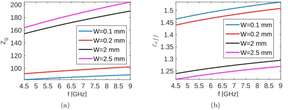
Figure 3.2 (a) Modified slot MNM design based on the Babinet principle. (b) Annular slotted ring structure with its design parameters. (c) Transmission line model of the modified slot MNM. f [GHz] 4.5 5 5.5 6 6.5 7 7.5 8 8.5 9 Z 0 100 120 140 160 180 200 W=0.1 mm W=0.2 mm W=2 mm W=2.5 mm (a) f [GHz] 4.5 5 5.5 6 6.5 7 7.5 8 8.5 9 εef f 1.25 1.3 1.35 1.4 1.45 1.5 W=0.1 mm W=0.2 mm W=2 mm W=2.5 mm (b)
Figure 3.3 (a) Characteristic impedance of a slot transmission line for different slot widths. (b) Effective permittivity of a slot transmission line for different slot widths. Thi-ckness of the substrate is 0.8 mm, relative permittivity of the substrate is 2.6.
transparent MNMs. The closed-form expressions are only valid when 0.0015 ≤ W/λ0 ≤ 1.9, 0.006 ≤ h/λ0 ≤ 0.06 and 2.22 ≤ εr ≤ 9.8, where W is the width of the slot line, h is the
thickness of the substrate and εr is the permittivity of the substrate [53]. The difficulty of
determining the electromagnetic response of a slot line is originated from its inherent field distribution such that the field lines are not concentrated into substrate as opposed micros-trip line. As it will be seen later, these properties impose some restrictions on the transparent MNM design.
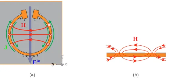
In order to have a rotating magnetic dipole moment response in a transverse plane, the unloaded structure shown in Fig. 3.1(a) should have a magnetic dipole moment response. Indeed as it can be seen from the sketched current and field distributions of the unloaded structure in Fig. 3.4(a) under plane wave illumination, the unloaded structure has a magne-tic dipole response, characterized with the magnemagne-tic field lines, in the plane transverse to
ez direction. Since the incident electrical field is directed into −ex direction, there will be charge a accumulation across the slot at the top and the bottom of the ring. This charge accumulation will create out-of phase counter-propagating currents around the slot. As can be seen in Fig. 3.4(b), the magnetic field lines are perpendicular to the P EC plane along slot since the counter-propagating currents forms a loop due to the subwavelength thickness of the slot and produce magnetic fields perpendicular to x − y plane. In addition, direction of the magnetic field lines along the slot depends on whether the counter-propagating currents forms a clockwise or a counter-clockwise loop. Therefore, the magnetic field lines are in the direction of +ezand −ezas can be seen in Fig. 3.4(a). These two out-of phase perpendicular magnetic field lines have to form a loop because of the non-existence of the magnetic charges (solenoidal nature of magnetic field lines) as in Fig. 3.4(b). The additional magnetic field lines drawn in Fig. 3.4(b) depicts the interaction of the neighboring unit-cells since the magnetic field lines around the slot should close on themselves. Thus, the unloaded annular slotted ring structure can be characterized with a magnetic dipole moment which has a transverse component in x − y plane and perpendicular components in +ez and −ez directions.
The unloaded annular slotted ring structure as shown in Fig. 3.4(a) shows a standing wave pattern in time domain such that the magnetic field lines are in the direction of either +ey or −ey. In order to achieve a magnetized ferrite-like non-reciprocal gyrotropic response one needs a rotating magnetic moment, which can be achieved by loading the annular slotted ring structure with an unidirectional component to break the time-reversal symmetry. If the unidirectional component is perfectly matched to the annular slotted ring structure at points